EP0997677A2 - Aufgeweitetes Rohr und Verbindungsanordnung hierfür - Google Patents
Aufgeweitetes Rohr und Verbindungsanordnung hierfür Download PDFInfo
- Publication number
- EP0997677A2 EP0997677A2 EP99118188A EP99118188A EP0997677A2 EP 0997677 A2 EP0997677 A2 EP 0997677A2 EP 99118188 A EP99118188 A EP 99118188A EP 99118188 A EP99118188 A EP 99118188A EP 0997677 A2 EP0997677 A2 EP 0997677A2
- Authority
- EP
- European Patent Office
- Prior art keywords
- flare
- tube
- single flare
- outer corner
- joint structure
- Prior art date
- Legal status (The legal status is an assumption and is not a legal conclusion. Google has not performed a legal analysis and makes no representation as to the accuracy of the status listed.)
- Granted
Links
- 239000012530 fluid Substances 0.000 claims description 10
- 230000008859 change Effects 0.000 claims description 6
- 230000008878 coupling Effects 0.000 abstract description 3
- 238000010168 coupling process Methods 0.000 abstract description 3
- 238000005859 coupling reaction Methods 0.000 abstract description 3
- 230000007423 decrease Effects 0.000 description 6
- 239000012141 concentrate Substances 0.000 description 4
- 230000002093 peripheral effect Effects 0.000 description 4
- 230000002829 reductive effect Effects 0.000 description 3
- 238000000576 coating method Methods 0.000 description 2
- 230000003292 diminished effect Effects 0.000 description 2
- 238000009434 installation Methods 0.000 description 2
- 230000000873 masking effect Effects 0.000 description 2
- 238000000034 method Methods 0.000 description 2
- 230000008569 process Effects 0.000 description 2
- 238000010276 construction Methods 0.000 description 1
- 230000003247 decreasing effect Effects 0.000 description 1
- 230000000694 effects Effects 0.000 description 1
- 230000005489 elastic deformation Effects 0.000 description 1
- 239000000446 fuel Substances 0.000 description 1
- JEIPFZHSYJVQDO-UHFFFAOYSA-N iron(III) oxide Inorganic materials O=[Fe]O[Fe]=O JEIPFZHSYJVQDO-UHFFFAOYSA-N 0.000 description 1
- 239000000463 material Substances 0.000 description 1
- 239000002184 metal Substances 0.000 description 1
- 238000012986 modification Methods 0.000 description 1
- 230000004048 modification Effects 0.000 description 1
- 229910052755 nonmetal Inorganic materials 0.000 description 1
- 239000004033 plastic Substances 0.000 description 1
- 230000003449 preventive effect Effects 0.000 description 1
- 230000003068 static effect Effects 0.000 description 1
- 235000013311 vegetables Nutrition 0.000 description 1
Images

Classifications
-
- F—MECHANICAL ENGINEERING; LIGHTING; HEATING; WEAPONS; BLASTING
- F16—ENGINEERING ELEMENTS AND UNITS; GENERAL MEASURES FOR PRODUCING AND MAINTAINING EFFECTIVE FUNCTIONING OF MACHINES OR INSTALLATIONS; THERMAL INSULATION IN GENERAL
- F16L—PIPES; JOINTS OR FITTINGS FOR PIPES; SUPPORTS FOR PIPES, CABLES OR PROTECTIVE TUBING; MEANS FOR THERMAL INSULATION IN GENERAL
- F16L19/00—Joints in which sealing surfaces are pressed together by means of a member, e.g. a swivel nut, screwed on, or into, one of the joint parts
- F16L19/02—Pipe ends provided with collars or flanges, integral with the pipe or not, pressed together by a screwed member
- F16L19/025—Pipe ends provided with collars or flanges, integral with the pipe or not, pressed together by a screwed member the pipe ends having integral collars or flanges
- F16L19/028—Pipe ends provided with collars or flanges, integral with the pipe or not, pressed together by a screwed member the pipe ends having integral collars or flanges the collars or flanges being obtained by deformation of the pipe wall
- F16L19/0286—Pipe ends provided with collars or flanges, integral with the pipe or not, pressed together by a screwed member the pipe ends having integral collars or flanges the collars or flanges being obtained by deformation of the pipe wall and being formed as a flange
-
- Y—GENERAL TAGGING OF NEW TECHNOLOGICAL DEVELOPMENTS; GENERAL TAGGING OF CROSS-SECTIONAL TECHNOLOGIES SPANNING OVER SEVERAL SECTIONS OF THE IPC; TECHNICAL SUBJECTS COVERED BY FORMER USPC CROSS-REFERENCE ART COLLECTIONS [XRACs] AND DIGESTS
- Y10—TECHNICAL SUBJECTS COVERED BY FORMER USPC
- Y10S—TECHNICAL SUBJECTS COVERED BY FORMER USPC CROSS-REFERENCE ART COLLECTIONS [XRACs] AND DIGESTS
- Y10S285/00—Pipe joints or couplings
- Y10S285/903—Corrugated
Definitions
- the present invention relates to a single flare tube and to a joint structure of the single flare tube.
- the single flare tube includes a tubular portion and a flare portion attached to the front end of the tubular portion.
- the joint structure of the single flare tube includes the single flare tube, a flare nut and a union.
- the joint structure of the single flare tube can be used, for example, in a fluid circuit in order to connect one part of the fluid circuit to another part of the fluid circuit.
- a joint structure of a single flare tube is well known among several kinds of joint structures of tubes.
- One example of a joint structure of a single flare tube is shown in Fig. 6.
- a cylindrical hole 101a is drilled into a union 101, and an internal thread 101b is cut in a part of the cylindrical hole 101a.
- An external thread 102b is cut in an outer peripheral surface of a flare nut 102, and the flare nut 102 is connected with the union 101 by screwing together the external thread 102b and the internal thread 101b.
- the flare nut 102 has a longitudinal through-hole 102a.
- a single flare tube 103 has a longitudinal through-hole 105a for flowing fluid, and includes a flare 104 and a tube 105.
- the tube 105 passes through the through-hole 102a of the flare nut 102.
- the flare 104 is positioned at the front end part of the single flare tube 103, and an outer peripheral circumference of the flare 104 extends radially outward.
- the outer diameter of the flare 104 progressively decreases closer to the front end of the flare 104, and thus a front slanting surface 104b of the flare 104 is nearly slant-shaped.
- the flare nut 102 with the single flare tube 103 positioned in the through-hole 102a is inserted into the cylindrical hole 101a.
- the flare nut 102 is tightened at the thread 101b of the union 101 and the thread 102b of the flare nut 102, the flare 104 is located between a front surface 102c of the flare nut 102 and a slant shaped inner wall 101c of the union 101, and the single flare tube 103 is coupled to the union 101.
- the conventional type flare 104 has a longitudinal section shaped like ⁇ , and is elastically longitudinally deformed by tightening the threads of the flare nut 102 and the union 101. It had been thought that by this elastic deformation, the front surface 104b of the flare 104 could be tightly fitted to the interior wall 101c of the union 101.
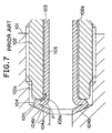
- the flare 104 can be plastically deformed by excessive tightening of the flare nut 102, as illustrated in Fig. 7.
- An inner circumferential groove 104a of the flare 104 then becomes out of shape, and not only the front end of the front surface 104b, but also the whole slanted, front surface 104b could contact the interior wall 101c of the union 101.
- the contact area between the flare 104 and the interior wall 101c increases, the contact pressure between both parts is reduced. Then, the sealability of this area also decreases.
- a phenomenon by which the flare 104 rotates together with the flare nut 102 could happen in the condition where the flare 104 is sandwiched and pushed between the front end of the flare nut 102 and the inner wall 101c of the union 101. If the flare nut 102 continues to be tightened until the flare 104 becomes out of shape completely and the gap of the inner circumferential groove 104a becomes substantially zero (as shown in Fig. 7) , a rotation angle of the flare 104 by this dual-rotation could become a non-negligible level. As a consequence, the single flare tube 103 could twist by an amount that can not be neglected.
- low friction oil for example, vegetable-based rust preventive oil
- an oil coating process is necessary which increases the cost. If the low friction oil accidentally happens to be placed on the front surface 104b, the friction between the front surface 104b and the inner wall 101c is lowered. Then, the flare 104 could be slippery to the inner wall 101c, which results in the dual-rotation of the flare 104 and the flare nut 102. Consequently, the twisting angle of the single flare tube 103 could become higher.
- the inner wall 101c must be masked in order to avoid being surface-coated and to prevent the friction between the slanting surface 104b and the inner wall 101c from becoming lower, and to prevent the flare 104 from rotating with the flare nut 102. Since the masking process is necessary, it causes the cost to increase and the reliability to be lowered.
- a curvature of an outer (radially outward facing) corner 103a located between the front end of the tube 105 and the rear end of the flare 104 is constant and high.
- the curvature of the outer corner 103a is high, a high tensile stress P is loaded to the surface of the outer corner 103a when the flare nut 102 is tightened firmly, and the tensile stress P on the outer corner 103a remains after fastening the single flare tube 103 to the union 101 with the nut 102.
- the fatigue strength of the single flare tube 103 becomes lower when the tensile stress P remains.
- Another object of the present invention is to provide a single flare tube and a joint structure of the single flare tube in which a flare is not easily plastically deformed and a tensile stress does not easily remain.
- a joint structure of a single flare tube includes a single flare tube, a first connector member and a second connector member.
- the single flare tube includes a tube and a flare, and the flare is coupled with the tube at the front end of the tube.
- the flare extends radially outward relative to a longitudinal axis of the tube.
- the first connector member can be, for example, a flare nut that has a through-hole for receiving the tube of the single flare tube.
- the second connector member can be, for example, a union that is connectable with the first connector member.
- the flare nut and the union can have, for example, threads that engage each other. A width of a narrow inner circumferential groove of the outer radially extending part of the flare does not substantially change when the single flare tube is pushed and coupled with the union by coupling the flare nut with the union.
- the flare Since the width of the narrow inner circumferential groove formed inside of the flare is not substantially changed when the single flare tube is pushed against the union by the flare nut, according to the present invention, the flare does not deform plastically, and a contacting area between a front slanting surface of the flare and an inner wall formed inside of the union does not increase. Accordingly, the contacting pressure between the slanting surface of the flare and the inner wall of the union does not decrease after tightening the flare nut with the union.
- the width of the narrow inner circumferential groove is substantially zero starting at a point that is radially closer to the longitudinal axis of the tube than is the external diameter of the tube.
- the narrow portion of the groove extends radially outward, and stays substantially zero when the single flare tube is pushed against and coupled with the union by connecting the flare nut with the union.
- the single flare tube having the flare formed with the above-mentioned narrow inner circumferential groove is not easily deformed plastically, the flare does not deform plastically and a contacting area between a front slanting surface of the flare and an inner wall formed inside of the union does not increase. Accordingly, the contacting pressure between the slanting front surface of the flare and the inner wall of the union does not decrease after tightening the flare nut with the union.
- a curvature at the (radially) outer side on the outer corner of the single flare tube is greater than a curvature at the (radially) inner side on the outer corner of the single flare tube on a longitudinal cut section.
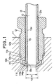
- Fig. 1 shows a longitudinal cross-sectional view of one embodiment of the present invention.
- a cylindrical hole 11a is drilled inside a union 11, and an interior thread 11b is cut in a part of the cylindrical hole 11a.
- the union 11 is not limited to the type shown in Fig. 1, and any type of member which is connectable with a flare tube is meant to be encompassed by the term union.
- An external thread 12b is cut in an outer peripheral surface of a flare nut 12, and the flare nut 12 is coupled with the union 11 by screwing the external thread 12b and the internal thread 11b.
- the flare nut 12 has a longitudinal through-hole 12a.
- a single flare tube 13 has a longitudinal through-hole 15a for flowing fluid, and includes a tube 15 and a flare 14.
- the tube 15 passes through the through-hole 12a of the flare nut 12.
- the flare 14 is positioned at the front end part of the single flare tube 13, and an outer peripheral circumference of the flare 14 extends radially outward of the tube 15 relative to the longitudinal axis of the flare tube 13.
- the outer diameter of the flare 104 progressively decreases closer to the front side of the flare 14, and thus a front surface 14b of the flare 14 is nearly slant-shaped.
- a first connector member (the flare nut) has threads that engage with threads of a second connector member (the union).
- the invention is not limited to this type of connection structure.
- the first and second connector members can attach to each other with a bayonet type of connection or a snap type of connection.
- the flare nut 12 with the single flare tube 13 positioning in the through-hole 12a is inserted into the cylindrical hole 11a.
- the flare 14 is located between a front surface 12c of the flare nut 12 and a slant shaped inner wall 11c of the union 11, and the single flare tube 13 is coupled to the union 11.
- the flare 14 extends radially outward at the front end part of the single flare tube 13, and the flare 14 protrudes beyond the front portion of the tube 15, and has a tapered, slanted front end.
- An inner circumferential groove 14a is formed at the inside of the flare 14 (i.e., on an inner surface of the flare 14), and a width of the inner circumferential groove 14a is substantially zero (i.e., the walls of the flare 14 on each side of the groove contact or almost contact each other). As shown on Fig.
- the width of the inner circumferential groove 14a is zero or substantially zero starting at a point that is radially closer to the longitudinal axis (the centerline) of the flare tube 13 than is the outer diamtere of the tube 15.
- the internal diameter r1 of the narrow portion of the groove 14a is less than the external diameter r2 of the tube 15.
- the rear side of the flare 14 connects gently and continuously to the front side of the tube 15.
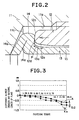
- An outer corner 13a of the connecting part between the flare 14 and the tube 15 curves smoothly and continuously, and a curvature at the radially outer side of the outer corner 13a is greater than a curvature at the radially inner side of the outer corner 13a when viewed on a longitudinal cut section.
- the curvature of the outer corner 13a of the single flare tube 13 is not constant, and the farther a part of the flare 14 is from the tube 15, the more sharply the outer corner 13a curves.
- a curvature at the radially outer side of the outer corner of the single flare tube 13 on a longitudinal cut section is greater than a curvature at the radially inner side of the outer corner of the single flare tube 13.
- the radius of curvature of the outer corner decreases (the curvature becomes tighter) from the tube 15 toward the flare 14.
- a curvature of an inner front corner 12d connecting a front surface 12c to the through-hole 12a of the flare nut 12 on a longitudinal cut section is not constant. As illustrated in Fig. 2, the more toward the front the inner front corner 12d is, the more sharply the inner front corner curves. On the contrary, the farther the inner front corner is from the front surface 12c, the more gradually the inner front corner curves.
- This shape of the flare nut 12 prevents the front surface 12c from intruding into the outer corner 13a, and makes the contacting area between the front surface 12c and the outer rear surface of the flare 14 more inner side of the outer rear surface of the flare 14 (i.e., the portion of the back surface of the flare which is angled to face the tube 15 is contacted).
- the width of the inner groove 14a is zero or substantially zero starting at a point that is radially closer to the longitudinal axis of the tube than is the outer diameter of the tube 15, the internal diameter r1 of the narrow portion of the inner groove 14a is smaller than the external diameter r2 of the tube 15. Due to this structure, a width of the narrow inner circumferential groove 14a inside the radially outward extending part of the flare 14 hardly varies (and is maintained at zero or substantially zero) when the flare 14 is pushed by the flare nut 12.
- the width of the inner groove 14a is substantially zero and stays substantially zero, though the single flare tube 13 is pushed and coupled with the union 11 by tightening the threads 11b, 12b of the union 11 and the flare nut 12, the inner circumferential groove 14a of the flare 14 does not change its shape by plastic deformation. Consequently, even if the slanting front surface 14b is strongly pushed against the inner wall 11c, the contacting area between the slanting surface 14b and the inner wall 11c does not increase. Accordingly, the contacting pressure of the area is maintained high and fluid inside of the single flare tube 13 and the union 11 does not leak.
- substantially zero means that not only the width of the narrow part of the inner circumferential groove 14a is zero but also the width does not change substantially when the flare nut 12 is tightened strongly.
- the above-mentioned condition is satisfied by setting an appropriate outer diameter, an appropriate wall thickness, an appropriate material, etc. of the single flare tube 13, or an appropriate shape of the flare 14 in which an internal diameter of the narrow part of the inner circumferential groove 14a is smaller than an external diameter of the tube 15.
- the flare 14 plastically deforms very little when the flare nut 12 is tightened strongly after the flare 14 is sandwiched between the front surface 12c of the flare nut 12 and the inner wall 11c of the union 11, an angle of the flare 14 rotated by the flare nut 12 changes very little. Accordingly, the single flare tube 13 does not twist substantially.
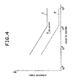
- Fig. 3 is a graph showing a comparison of a change in length of the flare 14 when tightening the flare nut 12 between this embodiment and the aforementioned prior art.
- the horizontal line shows fastening torque and the vertical line shows a difference between the changed longitudinal length and the original length of the flare 14.
- the solid line A shows characteristics of the flare 14 of the joint structure of the single flare tube 13 of this embodiment, and the dotted line B shows characteristics of the flare 104 of the prior art. According to this graph, the length difference of the flare 14 of the embodiment changes less than the length difference of the prior art.
- the tensile stress P occurs on the surface of the outer corner 13a of the single flare tube 13. Because the outer corner 13a curves gradually from the front of the tube 15 to the rear side of the flare 14, a lower tensile stress P remains on the surface of the outer corner 13a. Additionally, because the curvature of the outer corner 13a is low, added tensile stress to the outer corner 13a hardly concentrates when an external force is loaded to the single flare tube 13. Therefore, the total tensile stress on the outer corner 13a becomes lower. Consequently, the fatigue durability of the outer corner 13a becomes higher, and the durability of the single flare tube 13 is obtained.
- the shape of the front surface 12c and the inner front corner 12d of the flare nut 12 is designed so that the contacting area between the rear outer surface of the flare 14 and the front surface 12c is closer to the tube 15. It is known from experiments that the above-mentioned characteristic makes the tensile stress P lower. Therefore, the outer corner 13a of the flare 14 can have an increased fatigue durability.
- the shapes of the front surface 12c of the flare nut 12 and the rear outer surface of the flare 14 are designed so that the contacting area becomes larger. Consequently, the contacting pressure of this part is prevented from becoming too high.
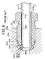
- Fig. 4 is a graph showing alternating stress versus cycles to fracture, comparing fatigue durability of the single flare tube of one embodiment of the present invention and the prior art.
- the horizontal line shows cycles to fracture of the single flare tubes
- the vertical line shows an alternating stress.
- the alternating stress is a half of a stress range.
- the stress range is a difference of a maximum stress and a minimum stress.
- the single flare tube 13 of this embodiment is shown by the solid line C
- the single flare tube 103 of the prior art is shown by the dotted line D. Comparing the two, the fatigue strength of the single flare tube 13 is 35% higher than the single flare tube 103.
- Fig. 5 shows diagrammatically the joint structure of the single flare tube of Fig. 1 applied to a brake system on a vehicle.
- an ABS (Antilock Brake System) actuator 21 is fixed to a body of the vehicle by way of a plurality of rubber mounts 22.
- the rubber mounts 22 prevent a vibration of the ABS actuator 21 from transmitting to the body of the vehicle.
- the single flare tube 13 is fixed to the body of the vehicle by a plurality of brackets 23 (in Fig. 5 only one bracket is shown). Pressured oil is supplied to the ABS actuator 21 by the joint structure of the single flare tube of this embodiment.
- the tensile stress of the outer corner 13a hardly concentrates when the external force is loaded to the single flare tube 13. As a result, the fatigue durability of the outer corner 13a becomes high, and the durability of the single flare tube 13 is secured.
- a certain level of vibration of the single flare tube 13 becomes tolerable in this embodiment. Consequently, a vibration-isolating performance from the ABS actuator 21 to the body of the vehicle can be improved by decreasing a spring rate of each rubber mount 22, and the number of the brackets 23 can be reduced and/or the size of each bracket 23 can be diminished.
- Many tubes are adopted in a brake system of a vehicle, and there are many joint structures of the tubes. If the number of the brackets fixing the tubes is reduced and the size of each bracket is diminished by adopting the aforementioned single flare tubes, a remarkable cost saving of the brake system can be realized.
- this embodiment can be applied not only to a hydraulic brake system but also to other hydraulic systems, fluid systems and/or fuel systems. Consequently, the total cost saving by adopting the single flare tube of this embodiment is remarkably high.
- the joint structure of the single flare tube of this invention is not only applied to piping installations of a vehicle, but also can be applied to any other piping/tubing installation, in the case where an end of a tube is fastened to a part. Additionally, non-metal could be used for the single flare tube as well as metal.
- a single flare tube (13), and a joint structure of the single flare tube makes a flare (14) of the single flare tube (13) hardly deformed plastically. Additionally, a tensile stress remains lower and is lower when the single flare tube (13) is fastened.
- a joint structure of the single flare tube coupled with a union (11) includes a single flare tube (13) having a tube (15) and a flare (14), a flare nut (12) having a thread (12b) and a through-hole (12a) that receives the tube of the single flare tube, and a union (11) having a thread (11b) for coupling with the thread (12b) of the flare nut (12).
- a width of a narrow inner circumferential groove (14a) of a radially outward extending part of the flare (14) is substantially zero and stays substantially zero when the single flare tube (13) is pushed against and coupled with the union (11) by fastening the threads (12b) of the flare nut (12) and the union (11) together.
- an internal diameter (r1) of the inner circumferential groove (14a) preferably is smaller than an external diameter (r2) of the tube (13).
- a curvature at a radially outer side of an outer corner (13a) of the single flare tube (13) (where the tube is connected with the flare) is larger than a curvature at a radially inner side of the outer corner (13a) of the single flare tube (13) along a longitudinal cut section of the single flare tube (13).
Landscapes
- Engineering & Computer Science (AREA)
- General Engineering & Computer Science (AREA)
- Mechanical Engineering (AREA)
- Joints With Pressure Members (AREA)
Applications Claiming Priority (2)
| Application Number | Priority Date | Filing Date | Title |
|---|---|---|---|
| JP30918998 | 1998-10-29 | ||
| JP30918998A JP3307345B2 (ja) | 1998-10-29 | 1998-10-29 | 管体の結合構造 |
Publications (3)
| Publication Number | Publication Date |
|---|---|
| EP0997677A2 true EP0997677A2 (de) | 2000-05-03 |
| EP0997677A3 EP0997677A3 (de) | 2002-11-06 |
| EP0997677B1 EP0997677B1 (de) | 2004-08-18 |
Family
ID=17990010
Family Applications (1)
| Application Number | Title | Priority Date | Filing Date |
|---|---|---|---|
| EP99118188A Expired - Lifetime EP0997677B1 (de) | 1998-10-29 | 1999-09-13 | Aufgeweitetes Rohr und Verbindungsanordnung hierfür |
Country Status (4)
| Country | Link |
|---|---|
| US (1) | US6663146B1 (de) |
| EP (1) | EP0997677B1 (de) |
| JP (1) | JP3307345B2 (de) |
| DE (1) | DE69919484T2 (de) |
Cited By (4)
| Publication number | Priority date | Publication date | Assignee | Title |
|---|---|---|---|---|
| EP1710483A4 (de) * | 2004-01-28 | 2008-04-09 | Sanoh Ind Co Ltd | Aufgeweitete endstruktur für rohr |
| EP2136119A1 (de) * | 2008-06-17 | 2009-12-23 | TI Automotive (Heidelberg) GmbH | Schraubelement und Rohranschlusseinrichtung für den Anschluss von Rohrleitungen |
| EP2706277A2 (de) | 2012-09-10 | 2014-03-12 | Cooper-Standard Automotive (Deutschland) GmbH | Rohrschraube zur Befestigung einer Rohrleitung und ein Verfahren zur Herstellung einer solchen Rohrschraube |
| CN110465599A (zh) * | 2019-08-30 | 2019-11-19 | 上海德朗汽车散热器制造有限公司 | 一种用于汽车全铝中冷器水管的扩口设备 |
Families Citing this family (14)
| Publication number | Priority date | Publication date | Assignee | Title |
|---|---|---|---|---|
| US20050194555A1 (en) * | 2004-03-05 | 2005-09-08 | Checkfluid Inc. | Flared Tube and Valve Connection |
| DE502004008971D1 (de) * | 2004-08-03 | 2009-03-26 | Ti Automotive Heidelberg Gmbh | Rohranschlusseinrichtung |
| DE102006061461A1 (de) * | 2006-07-26 | 2008-02-07 | Continental Teves Ag & Co. Ohg | Aggregat mit wenigstens zwei daran befestigter Hydraulikanschlüsse |
| CA2593305C (en) * | 2007-07-11 | 2008-10-14 | Stanislav Ivanovitch Pliassounov | Flared brake tube connector |
| US8079621B2 (en) | 2007-11-15 | 2011-12-20 | Lincoln Brass Works, Inc. | Reinforced bead tube design |
| JP5394206B2 (ja) * | 2009-11-20 | 2014-01-22 | 三桜工業株式会社 | 配管締結構造 |
| EP2679873B1 (de) * | 2012-06-29 | 2017-05-31 | TI Automotive (Heidelberg) GmbH | Verbindungsaggregat aus einer Kraftfahrzeugrohrleitung und einem Verbindungsfitting |
| US10072778B2 (en) * | 2015-01-08 | 2018-09-11 | Toyota Motor Engineering & Manufacturing North America, Inc. | Tube nut assembly |
| SE1551317A1 (en) * | 2015-10-13 | 2017-04-14 | Sapa As | Brake tube connector and brake tube connector assembly |
| DE102015122309A1 (de) * | 2015-12-18 | 2017-06-22 | Voss Fluid Gmbh | Rohrverbindung |
| US10479339B2 (en) | 2016-01-19 | 2019-11-19 | Ford Global Technologies, Llc | Flare-type brake line assembly and method of making the same |
| DE102017113195A1 (de) * | 2017-06-14 | 2018-12-20 | Bantboru Sanayi Ve Ticaret Anonim Sirketi | Rohrverbindungsvorichtung |
| US10502658B2 (en) * | 2017-09-08 | 2019-12-10 | Ford Global Technologies, Llc | System for a self-aligning exhaust sensor joint |
| US12173814B2 (en) | 2022-03-18 | 2024-12-24 | Martinrea International US Inc. | Female ISO flare union with integrated mating brake ISO F flare port |
Family Cites Families (20)
| Publication number | Priority date | Publication date | Assignee | Title |
|---|---|---|---|---|
| US1109920A (en) * | 1911-03-10 | 1914-09-08 | Joseph H Glauber | Basin, bath-cock, and other plumbing connection. |
| US1137955A (en) * | 1913-05-15 | 1915-05-04 | Clayton Mark | Pipe-coupling. |
| US1804814A (en) * | 1928-02-03 | 1931-05-12 | Simplex Copper Joint Company | Pipe coupling and method of forming the same |
| US2306702A (en) * | 1940-07-05 | 1942-12-29 | Nash Kelvinator Corp | Refrigerating apparatus |
| US2952481A (en) * | 1957-01-11 | 1960-09-13 | Weatherhead Co | Tube fitting having means to accommodate flexing of the tube |
| BE571070A (de) * | 1957-09-24 | |||
| US3092404A (en) * | 1961-01-25 | 1963-06-04 | Macwilliam Wallace | Packed screw threaded gland type tube coupling for thin walled tubing |
| US3265413A (en) * | 1963-07-25 | 1966-08-09 | Parker Hannifin Corp | Flared tube coupling joint and method for making the same |
| US3393930A (en) * | 1966-08-18 | 1968-07-23 | Parker Hannifin Corp | Coupling for thin-walled tubes |
| DE2132190A1 (de) * | 1971-06-29 | 1973-01-18 | Zako Rohrverbindungen Gmbh & C | Verfahren und vorrichtung zum doppelboerdeln von rohren |
| US3751002A (en) * | 1972-03-27 | 1973-08-07 | Chrysler Corp | Fluid coupling for high pressure spool valve hydraulic power steering gear |
| JPS5848456Y2 (ja) * | 1979-09-21 | 1983-11-05 | クラリオン株式会社 | フレヤ継手 |
| JPS62199577U (de) | 1986-06-09 | 1987-12-18 | ||
| DE3701555C1 (de) * | 1987-01-21 | 1988-07-07 | Mannesmann Ag | Rohrverbindung fuer duennwandige,kleinkalibrige Metallrohre |
| US4871199A (en) * | 1988-04-25 | 1989-10-03 | Ridenour Ralph Gaylord | Double bead tube fitting |
| DE4108741A1 (de) * | 1991-03-18 | 1992-09-24 | Bundy Gmbh | Rohrverbindung |
| DE4236323A1 (de) * | 1992-10-28 | 1994-05-05 | Teves Gmbh Alfred | Einrastbarer Anschluß einer starren Druckmittelleitung |
| JPH0712274A (ja) * | 1993-06-23 | 1995-01-17 | Toyota Motor Corp | フレア管継手 |
| US5529349A (en) * | 1993-08-25 | 1996-06-25 | Itt Corporation | Mounting apparatus with reduced resistance bead seal |
| US6113151A (en) * | 1998-01-27 | 2000-09-05 | Itt Manufacturing Enterprises, Inc. | High pressure quick connect and production process therefor |
-
1998
- 1998-10-29 JP JP30918998A patent/JP3307345B2/ja not_active Expired - Fee Related
-
1999
- 1999-09-13 DE DE69919484T patent/DE69919484T2/de not_active Expired - Lifetime
- 1999-09-13 EP EP99118188A patent/EP0997677B1/de not_active Expired - Lifetime
-
2000
- 2000-10-23 US US09/693,820 patent/US6663146B1/en not_active Expired - Fee Related
Non-Patent Citations (1)
| Title |
|---|
| None |
Cited By (10)
| Publication number | Priority date | Publication date | Assignee | Title |
|---|---|---|---|---|
| EP1710483A4 (de) * | 2004-01-28 | 2008-04-09 | Sanoh Ind Co Ltd | Aufgeweitete endstruktur für rohr |
| CN100543350C (zh) * | 2004-01-28 | 2009-09-23 | 三樱工业株式会社 | 管子的扩口形端部结构 |
| US7600792B2 (en) | 2004-01-28 | 2009-10-13 | Sanoh Kogyo Kabushiki Kaisha | Flare-shaped end structure for tube |
| EP2136119A1 (de) * | 2008-06-17 | 2009-12-23 | TI Automotive (Heidelberg) GmbH | Schraubelement und Rohranschlusseinrichtung für den Anschluss von Rohrleitungen |
| US8172278B2 (en) | 2008-06-17 | 2012-05-08 | Ti Automotive (Heidelberg) Gmbh | Threaded component and device for connecting piping |
| CN101608722B (zh) * | 2008-06-17 | 2014-08-27 | Ti汽车海德堡有限公司 | 用于连接管件的装置 |
| EP2706277A2 (de) | 2012-09-10 | 2014-03-12 | Cooper-Standard Automotive (Deutschland) GmbH | Rohrschraube zur Befestigung einer Rohrleitung und ein Verfahren zur Herstellung einer solchen Rohrschraube |
| DE102012108433C5 (de) | 2012-09-10 | 2022-04-14 | Cooper-Standard Automotive (Deutschland) Gmbh | Rohrschraube zur Befestigung einer Rohrleitung und ein Verfahren zur Herstellung einer solchen Rohrschraube |
| DE102012108433C9 (de) | 2012-09-10 | 2022-11-24 | Cooper-Standard Automotive (Deutschland) Gmbh | Rohrschraube zur Befestigung einer Rohrleitung und ein Verfahren zur Herstellung einer solchen Rohrschraube |
| CN110465599A (zh) * | 2019-08-30 | 2019-11-19 | 上海德朗汽车散热器制造有限公司 | 一种用于汽车全铝中冷器水管的扩口设备 |
Also Published As
| Publication number | Publication date |
|---|---|
| JP3307345B2 (ja) | 2002-07-24 |
| US6663146B1 (en) | 2003-12-16 |
| DE69919484T2 (de) | 2005-08-18 |
| DE69919484D1 (de) | 2004-09-23 |
| JP2000130657A (ja) | 2000-05-12 |
| EP0997677B1 (de) | 2004-08-18 |
| EP0997677A3 (de) | 2002-11-06 |
Similar Documents
| Publication | Publication Date | Title |
|---|---|---|
| EP0997677B1 (de) | Aufgeweitetes Rohr und Verbindungsanordnung hierfür | |
| US5667255A (en) | Joint structure for joining a branch member to a high pressure fuel rail | |
| CN103195864B (zh) | 橡胶支架 | |
| EP0619785B1 (de) | Gleitbuchse mit axialbewegungsbegrenzung für eine stabilisatorstange | |
| US6616130B2 (en) | Cylindrical vibration-isolating device | |
| WO1998012467A1 (en) | Mounting arrangement for supporting a hydraulic control unit of a vehicular braking system | |
| JP2006144972A (ja) | 防振ブッシュ組付構造 | |
| CN110050144A (zh) | 配备有振动阻尼构件的空调装置压缩机 | |
| JPH11500514A (ja) | 液体配管接続装置 | |
| US11462854B2 (en) | Electrical connector with a mounting flange and method of assembling same | |
| US5141259A (en) | Flexible connector | |
| US4648634A (en) | Hose connection | |
| JPH1182853A (ja) | 流体輸送管の外套管構造 | |
| US5983450A (en) | Through-wall bushing | |
| US7040668B2 (en) | Tube joint | |
| US5732985A (en) | Coupling hardware | |
| CN118391521A (zh) | 流体连接组件 | |
| US12233681B2 (en) | Serration embedment in coupling assembly of a bushing of an automotive suspension link | |
| JP4102587B2 (ja) | 金属管とゴムホースとの継手具 | |
| CN219866737U (zh) | 用于管道对接的密封圈 | |
| CN222937424U (zh) | 一种防止松动的扣压接头 | |
| US12194807B2 (en) | One-way installation for a bushing of an automotive suspension link | |
| JP3620508B2 (ja) | 管体の結合構造 | |
| GB2436602A (en) | Pipe coupling device for connecting a pipe to a gas valve located in a connection box | |
| KR20250111204A (ko) | 관 조인트용 회전 방지 부재 및 관 조인트 유닛 |
Legal Events
| Date | Code | Title | Description |
|---|---|---|---|
| PUAI | Public reference made under article 153(3) epc to a published international application that has entered the european phase |
Free format text: ORIGINAL CODE: 0009012 |
|
| 17P | Request for examination filed |
Effective date: 19990914 |
|
| AK | Designated contracting states |
Kind code of ref document: A2 Designated state(s): AT BE CH CY DE DK ES FI FR GB GR IE IT LI LU MC NL PT SE |
|
| AX | Request for extension of the european patent |
Free format text: AL;LT;LV;MK;RO;SI |
|
| PUAL | Search report despatched |
Free format text: ORIGINAL CODE: 0009013 |
|
| AK | Designated contracting states |
Kind code of ref document: A3 Designated state(s): AT BE CH CY DE DK ES FI FR GB GR IE IT LI LU MC NL PT SE |
|
| AX | Request for extension of the european patent |
Free format text: AL;LT;LV;MK;RO;SI |
|
| 17Q | First examination report despatched |
Effective date: 20030514 |
|
| AKX | Designation fees paid |
Designated state(s): DE FR GB |
|
| GRAP | Despatch of communication of intention to grant a patent |
Free format text: ORIGINAL CODE: EPIDOSNIGR1 |
|
| GRAS | Grant fee paid |
Free format text: ORIGINAL CODE: EPIDOSNIGR3 |
|
| GRAA | (expected) grant |
Free format text: ORIGINAL CODE: 0009210 |
|
| AK | Designated contracting states |
Kind code of ref document: B1 Designated state(s): DE FR GB |
|
| REG | Reference to a national code |
Ref country code: GB Ref legal event code: FG4D |
|
| REG | Reference to a national code |
Ref country code: IE Ref legal event code: FG4D |
|
| REF | Corresponds to: |
Ref document number: 69919484 Country of ref document: DE Date of ref document: 20040923 Kind code of ref document: P |
|
| ET | Fr: translation filed | ||
| PLBE | No opposition filed within time limit |
Free format text: ORIGINAL CODE: 0009261 |
|
| STAA | Information on the status of an ep patent application or granted ep patent |
Free format text: STATUS: NO OPPOSITION FILED WITHIN TIME LIMIT |
|
| REG | Reference to a national code |
Ref country code: IE Ref legal event code: MM4A |
|
| 26N | No opposition filed |
Effective date: 20050519 |
|
| REG | Reference to a national code |
Ref country code: GB Ref legal event code: 746 Effective date: 20071206 |
|
| PGFP | Annual fee paid to national office [announced via postgrant information from national office to epo] |
Ref country code: DE Payment date: 20130911 Year of fee payment: 15 |
|
| PGFP | Annual fee paid to national office [announced via postgrant information from national office to epo] |
Ref country code: GB Payment date: 20130911 Year of fee payment: 15 Ref country code: FR Payment date: 20130910 Year of fee payment: 15 |
|
| REG | Reference to a national code |
Ref country code: DE Ref legal event code: R119 Ref document number: 69919484 Country of ref document: DE |
|
| GBPC | Gb: european patent ceased through non-payment of renewal fee |
Effective date: 20140913 |
|
| REG | Reference to a national code |
Ref country code: FR Ref legal event code: ST Effective date: 20150529 |
|
| PG25 | Lapsed in a contracting state [announced via postgrant information from national office to epo] |
Ref country code: GB Free format text: LAPSE BECAUSE OF NON-PAYMENT OF DUE FEES Effective date: 20140913 Ref country code: DE Free format text: LAPSE BECAUSE OF NON-PAYMENT OF DUE FEES Effective date: 20150401 |
|
| PG25 | Lapsed in a contracting state [announced via postgrant information from national office to epo] |
Ref country code: FR Free format text: LAPSE BECAUSE OF NON-PAYMENT OF DUE FEES Effective date: 20140930 |