EP0997682A2 - Druckaufbauverdampfer - Google Patents
Druckaufbauverdampfer Download PDFInfo
- Publication number
- EP0997682A2 EP0997682A2 EP99120475A EP99120475A EP0997682A2 EP 0997682 A2 EP0997682 A2 EP 0997682A2 EP 99120475 A EP99120475 A EP 99120475A EP 99120475 A EP99120475 A EP 99120475A EP 0997682 A2 EP0997682 A2 EP 0997682A2
- Authority
- EP
- European Patent Office
- Prior art keywords
- liquid
- steam
- steam line
- housing
- storage container
- Prior art date
- Legal status (The legal status is an assumption and is not a legal conclusion. Google has not performed a legal analysis and makes no representation as to the accuracy of the status listed.)
- Withdrawn
Links
- 239000007788 liquid Substances 0.000 claims abstract description 65
- 238000001704 evaporation Methods 0.000 claims abstract description 12
- 238000010438 heat treatment Methods 0.000 claims abstract description 10
- 230000008020 evaporation Effects 0.000 claims abstract description 8
- 239000001257 hydrogen Substances 0.000 claims description 31
- 229910052739 hydrogen Inorganic materials 0.000 claims description 31
- UFHFLCQGNIYNRP-UHFFFAOYSA-N Hydrogen Chemical compound [H][H] UFHFLCQGNIYNRP-UHFFFAOYSA-N 0.000 claims description 30
- 238000005192 partition Methods 0.000 claims description 8
- 239000004020 conductor Substances 0.000 claims description 2
- 150000002431 hydrogen Chemical class 0.000 claims description 2
- 239000007789 gas Substances 0.000 description 6
- 239000000446 fuel Substances 0.000 description 5
- 241001503485 Mammuthus Species 0.000 description 3
- 239000011347 resin Substances 0.000 description 2
- 229920005989 resin Polymers 0.000 description 2
- 238000009835 boiling Methods 0.000 description 1
- 238000002485 combustion reaction Methods 0.000 description 1
- 238000009833 condensation Methods 0.000 description 1
- 230000005494 condensation Effects 0.000 description 1
- 230000006378 damage Effects 0.000 description 1
- 230000003247 decreasing effect Effects 0.000 description 1
- 239000004744 fabric Substances 0.000 description 1
- 230000002631 hypothermal effect Effects 0.000 description 1
- 238000009413 insulation Methods 0.000 description 1
- 239000000203 mixture Substances 0.000 description 1
- 230000000149 penetrating effect Effects 0.000 description 1
- 230000000630 rising effect Effects 0.000 description 1
- 238000013517 stratification Methods 0.000 description 1
- 230000008016 vaporization Effects 0.000 description 1
Images
Classifications
-
- F—MECHANICAL ENGINEERING; LIGHTING; HEATING; WEAPONS; BLASTING
- F17—STORING OR DISTRIBUTING GASES OR LIQUIDS
- F17C—VESSELS FOR CONTAINING OR STORING COMPRESSED, LIQUEFIED OR SOLIDIFIED GASES; FIXED-CAPACITY GAS-HOLDERS; FILLING VESSELS WITH, OR DISCHARGING FROM VESSELS, COMPRESSED, LIQUEFIED, OR SOLIDIFIED GASES
- F17C9/00—Methods or apparatus for discharging liquefied or solidified gases from vessels not under pressure
- F17C9/02—Methods or apparatus for discharging liquefied or solidified gases from vessels not under pressure with change of state, e.g. vaporisation
-
- F—MECHANICAL ENGINEERING; LIGHTING; HEATING; WEAPONS; BLASTING
- F17—STORING OR DISTRIBUTING GASES OR LIQUIDS
- F17C—VESSELS FOR CONTAINING OR STORING COMPRESSED, LIQUEFIED OR SOLIDIFIED GASES; FIXED-CAPACITY GAS-HOLDERS; FILLING VESSELS WITH, OR DISCHARGING FROM VESSELS, COMPRESSED, LIQUEFIED, OR SOLIDIFIED GASES
- F17C2205/00—Vessel construction, in particular mounting arrangements, attachments or identifications means
- F17C2205/03—Fluid connections, filters, valves, closure means or other attachments
- F17C2205/0302—Fittings, valves, filters, or components in connection with the gas storage device
- F17C2205/0352—Pipes
-
- F—MECHANICAL ENGINEERING; LIGHTING; HEATING; WEAPONS; BLASTING
- F17—STORING OR DISTRIBUTING GASES OR LIQUIDS
- F17C—VESSELS FOR CONTAINING OR STORING COMPRESSED, LIQUEFIED OR SOLIDIFIED GASES; FIXED-CAPACITY GAS-HOLDERS; FILLING VESSELS WITH, OR DISCHARGING FROM VESSELS, COMPRESSED, LIQUEFIED, OR SOLIDIFIED GASES
- F17C2221/00—Handled fluid, in particular type of fluid
- F17C2221/01—Pure fluids
- F17C2221/012—Hydrogen
-
- F—MECHANICAL ENGINEERING; LIGHTING; HEATING; WEAPONS; BLASTING
- F17—STORING OR DISTRIBUTING GASES OR LIQUIDS
- F17C—VESSELS FOR CONTAINING OR STORING COMPRESSED, LIQUEFIED OR SOLIDIFIED GASES; FIXED-CAPACITY GAS-HOLDERS; FILLING VESSELS WITH, OR DISCHARGING FROM VESSELS, COMPRESSED, LIQUEFIED, OR SOLIDIFIED GASES
- F17C2223/00—Handled fluid before transfer, i.e. state of fluid when stored in the vessel or before transfer from the vessel
- F17C2223/01—Handled fluid before transfer, i.e. state of fluid when stored in the vessel or before transfer from the vessel characterised by the phase
- F17C2223/0146—Two-phase
- F17C2223/0153—Liquefied gas, e.g. LPG, GPL
- F17C2223/0161—Liquefied gas, e.g. LPG, GPL cryogenic, e.g. LNG, GNL, PLNG
-
- F—MECHANICAL ENGINEERING; LIGHTING; HEATING; WEAPONS; BLASTING
- F17—STORING OR DISTRIBUTING GASES OR LIQUIDS
- F17C—VESSELS FOR CONTAINING OR STORING COMPRESSED, LIQUEFIED OR SOLIDIFIED GASES; FIXED-CAPACITY GAS-HOLDERS; FILLING VESSELS WITH, OR DISCHARGING FROM VESSELS, COMPRESSED, LIQUEFIED, OR SOLIDIFIED GASES
- F17C2223/00—Handled fluid before transfer, i.e. state of fluid when stored in the vessel or before transfer from the vessel
- F17C2223/03—Handled fluid before transfer, i.e. state of fluid when stored in the vessel or before transfer from the vessel characterised by the pressure level
- F17C2223/033—Small pressure, e.g. for liquefied gas
-
- F—MECHANICAL ENGINEERING; LIGHTING; HEATING; WEAPONS; BLASTING
- F17—STORING OR DISTRIBUTING GASES OR LIQUIDS
- F17C—VESSELS FOR CONTAINING OR STORING COMPRESSED, LIQUEFIED OR SOLIDIFIED GASES; FIXED-CAPACITY GAS-HOLDERS; FILLING VESSELS WITH, OR DISCHARGING FROM VESSELS, COMPRESSED, LIQUEFIED, OR SOLIDIFIED GASES
- F17C2223/00—Handled fluid before transfer, i.e. state of fluid when stored in the vessel or before transfer from the vessel
- F17C2223/04—Handled fluid before transfer, i.e. state of fluid when stored in the vessel or before transfer from the vessel characterised by other properties of handled fluid before transfer
- F17C2223/042—Localisation of the removal point
- F17C2223/043—Localisation of the removal point in the gas
- F17C2223/045—Localisation of the removal point in the gas with a dip tube
-
- F—MECHANICAL ENGINEERING; LIGHTING; HEATING; WEAPONS; BLASTING
- F17—STORING OR DISTRIBUTING GASES OR LIQUIDS
- F17C—VESSELS FOR CONTAINING OR STORING COMPRESSED, LIQUEFIED OR SOLIDIFIED GASES; FIXED-CAPACITY GAS-HOLDERS; FILLING VESSELS WITH, OR DISCHARGING FROM VESSELS, COMPRESSED, LIQUEFIED, OR SOLIDIFIED GASES
- F17C2227/00—Transfer of fluids, i.e. method or means for transferring the fluid; Heat exchange with the fluid
- F17C2227/03—Heat exchange with the fluid
- F17C2227/0302—Heat exchange with the fluid by heating
-
- F—MECHANICAL ENGINEERING; LIGHTING; HEATING; WEAPONS; BLASTING
- F17—STORING OR DISTRIBUTING GASES OR LIQUIDS
- F17C—VESSELS FOR CONTAINING OR STORING COMPRESSED, LIQUEFIED OR SOLIDIFIED GASES; FIXED-CAPACITY GAS-HOLDERS; FILLING VESSELS WITH, OR DISCHARGING FROM VESSELS, COMPRESSED, LIQUEFIED, OR SOLIDIFIED GASES
- F17C2227/00—Transfer of fluids, i.e. method or means for transferring the fluid; Heat exchange with the fluid
- F17C2227/03—Heat exchange with the fluid
- F17C2227/0367—Localisation of heat exchange
- F17C2227/0369—Localisation of heat exchange in or on a vessel
- F17C2227/0374—Localisation of heat exchange in or on a vessel in the liquid
-
- F—MECHANICAL ENGINEERING; LIGHTING; HEATING; WEAPONS; BLASTING
- F17—STORING OR DISTRIBUTING GASES OR LIQUIDS
- F17C—VESSELS FOR CONTAINING OR STORING COMPRESSED, LIQUEFIED OR SOLIDIFIED GASES; FIXED-CAPACITY GAS-HOLDERS; FILLING VESSELS WITH, OR DISCHARGING FROM VESSELS, COMPRESSED, LIQUEFIED, OR SOLIDIFIED GASES
- F17C2270/00—Applications
- F17C2270/01—Applications for fluid transport or storage
- F17C2270/0165—Applications for fluid transport or storage on the road
- F17C2270/0168—Applications for fluid transport or storage on the road by vehicles
- F17C2270/0171—Trucks
-
- F—MECHANICAL ENGINEERING; LIGHTING; HEATING; WEAPONS; BLASTING
- F17—STORING OR DISTRIBUTING GASES OR LIQUIDS
- F17C—VESSELS FOR CONTAINING OR STORING COMPRESSED, LIQUEFIED OR SOLIDIFIED GASES; FIXED-CAPACITY GAS-HOLDERS; FILLING VESSELS WITH, OR DISCHARGING FROM VESSELS, COMPRESSED, LIQUEFIED, OR SOLIDIFIED GASES
- F17C2270/00—Applications
- F17C2270/01—Applications for fluid transport or storage
- F17C2270/0165—Applications for fluid transport or storage on the road
- F17C2270/0168—Applications for fluid transport or storage on the road by vehicles
- F17C2270/0176—Buses
-
- F—MECHANICAL ENGINEERING; LIGHTING; HEATING; WEAPONS; BLASTING
- F17—STORING OR DISTRIBUTING GASES OR LIQUIDS
- F17C—VESSELS FOR CONTAINING OR STORING COMPRESSED, LIQUEFIED OR SOLIDIFIED GASES; FIXED-CAPACITY GAS-HOLDERS; FILLING VESSELS WITH, OR DISCHARGING FROM VESSELS, COMPRESSED, LIQUEFIED, OR SOLIDIFIED GASES
- F17C2270/00—Applications
- F17C2270/01—Applications for fluid transport or storage
- F17C2270/0165—Applications for fluid transport or storage on the road
- F17C2270/0168—Applications for fluid transport or storage on the road by vehicles
- F17C2270/0178—Cars
-
- F—MECHANICAL ENGINEERING; LIGHTING; HEATING; WEAPONS; BLASTING
- F17—STORING OR DISTRIBUTING GASES OR LIQUIDS
- F17C—VESSELS FOR CONTAINING OR STORING COMPRESSED, LIQUEFIED OR SOLIDIFIED GASES; FIXED-CAPACITY GAS-HOLDERS; FILLING VESSELS WITH, OR DISCHARGING FROM VESSELS, COMPRESSED, LIQUEFIED, OR SOLIDIFIED GASES
- F17C2270/00—Applications
- F17C2270/01—Applications for fluid transport or storage
- F17C2270/0165—Applications for fluid transport or storage on the road
- F17C2270/0184—Fuel cells
-
- Y—GENERAL TAGGING OF NEW TECHNOLOGICAL DEVELOPMENTS; GENERAL TAGGING OF CROSS-SECTIONAL TECHNOLOGIES SPANNING OVER SEVERAL SECTIONS OF THE IPC; TECHNICAL SUBJECTS COVERED BY FORMER USPC CROSS-REFERENCE ART COLLECTIONS [XRACs] AND DIGESTS
- Y02—TECHNOLOGIES OR APPLICATIONS FOR MITIGATION OR ADAPTATION AGAINST CLIMATE CHANGE
- Y02E—REDUCTION OF GREENHOUSE GAS [GHG] EMISSIONS, RELATED TO ENERGY GENERATION, TRANSMISSION OR DISTRIBUTION
- Y02E60/00—Enabling technologies; Technologies with a potential or indirect contribution to GHG emissions mitigation
- Y02E60/30—Hydrogen technology
- Y02E60/32—Hydrogen storage
Definitions
- the invention relates to a device for building up pressure in a storage container for cryogenic liquids with a housing which has at least one Inlet opening for liquid and inside a heating device for evaporation of liquid and a steam line arranged in the upper third of the housing for removing the vapor bubbles formed during evaporation.
- the filling pressure is 3 to 4 bar just enough for proper engine operation.
- the use of fuel cells as a vehicle drive is currently one Hydrogen supply under a pressure of 10 bar required.
- a storage of the Hydrogen at a pressure of 10 bar and a corresponding one is disadvantageous because the Storage capacity due to the decreasing density with increasing temperature of liquid hydrogen drops significantly.
- the one stored at a pressure of 3 to 4 bar Hydrogen is first compressed to 10 bar before being fed to the fuel cell can be.
- the pressure increase can, for example, by introducing additional gaseous hydrogen in the storage tank or by evaporating a part of liquid hydrogen can be achieved.
- Such a device for Pressure build-up is known for example from DE 42 12 626 A1.
- a mammoth pump is attached to the bottom of the storage tank Pump heating liquid hydrogen partially entering the mammoth pump is evaporated. The resulting gas bubbles tear over liquid hydrogen with a riser up into the gas space of the storage tank, where this is finally evaporated by means of an evaporator heater.
- the object of the present invention is a device of the type mentioned to demonstrate that a simple, fast and secure way to build pressure in a storage container for cryogenic liquids.
- a housing is provided in the container, which has at least one inlet opening for liquid. Inside the case there is a heating device with the help of which part of the liquid can be evaporated.
- the resulting steam is fed through a steam line dissipated into the headspace of the storage container.
- the cross section of the steam pipe is chosen so that the flow resistance of the gas bubbles is so low that they carry little or no liquid with them. In contrast to one Mammoth pump or bubble column is therefore not in the headspace of the storage tank second heating necessary to evaporate the liquid transported upwards.
- the cross-sectional area of the steam line is advantageously greater than the sum of the Cross-sectional areas of the operation of the device simultaneously through this Cross-sectional area of the steam line passing through steam bubbles.
- the cross section the steam line is accordingly based on the performance of the heater to interpret.
- the steam line is preferably arranged at the highest point of the housing. In this way, essentially only steam is present at the entrance to the steam line, so that a transport of liquid through the steam line almost completely is excluded.
- the housing and / or the steam line are advantageously thermally insulated.
- the housing and / or the steam line are preferably insulated in that they are double-walled and the gap between the Both walls have an inlet opening for steam and / or liquid.
- the invention in addition to the device for building up pressure, relates to one Storage container also on a storage container for cryogenic liquids.
- This has a housing inside, preferably near its bottom, which has at least one inlet opening for liquid and one inside Has heating device for the evaporation of liquid.
- a Steam line for removing the vapor bubbles created during evaporation. According to the cross section of the steam line is so large that more steam than Liquid is discharged through the steam line.
- thermodynamic system present in the tank is therefore endeavors to reconcile hydrogen gas by condensing it back bring about thermal conditions of gas and liquid.
- Such a storage container is therefore advantageously improved in that the Storage containers through a variety of partitions that result from a bad heat-conducting material, is divided into cells, the maximum Expansion in a plane perpendicular to the partition walls less than 50 mm, is preferably less than 10 mm, particularly preferably less than 5 mm. Because of the Use of partitions in the storage container and the invention Dimensioning of the resulting cells is therefore ensured that a or already present in the liquid stored in the storage container targeted temperature stratification remains.
- the invention has been particularly useful in the storage of liquid hydrogen proven in a motor vehicle.
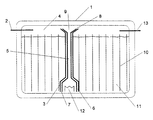
- FIG. 1 there is a storage container 1 for a hydrogen-powered vehicle Fuel cell technology is shown, which under driving hydrogen under a pressure of 10 bar is required.
- the hydrogen is initially at low pressure, for example 1 to 4 bar, in the storage container 1 via the Feed line 2 introduced.
- the pressure in the container 1 increased by vaporizing liquid.
- the steam line 5 has a diameter of 20 mm.
- the housing 3 and the steam line 5 are double-walled, the gap 6 existing between the walls is an inlet and Has outlet openings 7, 8 for liquid or gas.
- the one through this Inlet openings 7, 8 penetrating into the gap 6 liquid or gaseous Hydrogen is used for insulation between the rising in the steam pipe 5 gaseous hydrogen and the liquid hydrogen surrounding the housing.
- the storage container 1 is arranged by a plurality of vertically Partitions 10 divided, which are shaped and glued together so that results in a honeycomb structure in cross section.
- the maximum extension 11 one of these honeycomb cells in a plane perpendicular to the partition walls 10 is 6 mm.
- the partitions themselves consist of a resin soaked in resin Knitted fabric, which is impermeable to liquids and poorly conductive.
- the uppermost layers of liquid form an insulating layer prevent further back condensation.
- a pressure of 10 bar which has a boiling temperature of about 31 K. corresponds to maintain, while the liquid hydrogen to about 25 K. is hypothermic.
- the additional subdivision of the storage container 1 into individual cells prevents liquid movements in the storage container 1 that lead to a Destruction of the temperature gradient in the liquid hydrogen could result.
- the gaseous hydrogen is fed to the fuel cells via line 13.
- the invention thus makes it possible to use hydrogen in liquid form at low Temperature is stored in gaseous form under high pressure of, for example, 10 bar to provide.
Landscapes
- Engineering & Computer Science (AREA)
- Mechanical Engineering (AREA)
- General Engineering & Computer Science (AREA)
- Filling Or Discharging Of Gas Storage Vessels (AREA)
- Cooling, Air Intake And Gas Exhaust, And Fuel Tank Arrangements In Propulsion Units (AREA)
Abstract
Description
- Figur
- einen erfindungsgemäßen Speichertank.
Claims (10)
- Vorrichtung zum Druckaufbau in einem Speicherbehälter für kryogene Flüssigkeiten mit einem Gehäuse, welches zumindest eine Eintrittsöffnung für Flüssigkeit und im Inneren eine Heizvorrichtung zur Verdampfung von Flüssigkeit sowie eine im oberen Drittel des Gehäuses angeordnete Dampfleitung zum Abführen der bei der Verdampfung entstehenden Dampfblasen aufweist, dadurch gekennzeichnet, daß der Querschnitt der Dampfleitung so groß ist, daß beim Betrieb der Vorrichtung mehr Dampf als Flüssigkeit, vorzugsweise im wesentlichen nur Dampf, durch die Dampfleitung abgeführt wird.
- Vorrichtung nach Anspruch 1, dadurch gekennzeichnet, daß die Querschnittsfläche der Dampfleitung größer als die Summe der Querschnittsflächen der beim Betrieb der Vorrichtung gleichzeitig durch diese Querschnittsfläche der Dampfleitung durchtretenden Dampfblasen ist.
- Vorrichtung nach einem der Ansprüche 1 oder 2, dadurch gekennzeichnet, daß die Dampfleitung am höchsten Punkt des Gehäuses angeordnet ist.
- Vorrichtung nach einem der Ansprüche 1 bis 3, dadurch gekennzeichnet, daß das Gehäuse und/oder die Dampfleitung thermisch isoliert sind.
- Vorrichtung nach einem der Ansprüche 1 bis 4, dadurch gekennzeichnet, daß das Gehäuse und/oder die Dampfleitung doppelwandig ausgebildet sind und der Spalt zwischen den beiden Wänden eine Eintrittsöffnung für Dampf und/oder Flüssigkeit besitzt.
- Vorrichtung nach einem der Ansprüche 1 bis 5, dadurch gekennzeichnet, daß an dem nicht mit dem Gehäuse verbundenen Ende der Dampfleitung eine Vorrichtung zum Zurückhalten von Flüssigkeit vorgesehen ist.
- Vorrichtung nach einem der Ansprüche 1 bis 6 zum Druckaufbau in einem Speicherbehälter für flüssigen Wasserstoff, dadurch gekennzeichnet, daß im Querschnitt die minimale Ausdehnung der Dampfleitung mehr als 5 mm, bevorzugt mehr als 10 mm, besonders bevorzugt mehr als 20 mm beträgt.
- Speicherbehälter für kryogene Flüssigkeiten mit einem in seinem Inneren, vorzugsweise in der Nähe seines Bodens, angeordneten Gehäuse, welches zumindest eine Eintrittsöffnung für Flüssigkeit und im Inneren eine Heizvorrichtung zur Verdampfung von Flüssigkeit aufweist, sowie mit einer zwischen dem Gehäuse und einer Stelle oberhalb der maximalen Füllhöhe des Speicherbehälters verlaufenden Dampfleitung zum Abführen der bei der Verdampfung entstehenden Dampfblasen, dadurch gekennzeichnet, daß der Querschnitt der Dampfleitung so groß ist, daß mehr Dampf als Flüssigkeit durch die Dampfleitung abgeführt wird.
- Speicherbehälter nach Anspruch 8, dadurch gekennzeichnet, daß der Speicherbehälter durch eine Vielzahl von Trennwänden, die aus einem schlecht wärmeleitenden Material bestehen, in Zellen unterteilt ist, deren maximale Ausdehnung in einer Ebene senkrecht zu den Trennwänden kleiner als 50 mm, bevorzugt kleiner als 10 mm, besonders bevorzugt kleiner als 5 mm ist.
- Verwendung eines Speicherbehälters nach einem der Ansprüche 8 oder 9 zur Speicherung von flüssigem Wasserstoff in einem Kraftfahrzeug.
Applications Claiming Priority (2)
| Application Number | Priority Date | Filing Date | Title |
|---|---|---|---|
| DE19849766A DE19849766C1 (de) | 1998-10-28 | 1998-10-28 | Druckaufbauverdampfer |
| DE19849766 | 1998-10-28 |
Publications (2)
| Publication Number | Publication Date |
|---|---|
| EP0997682A2 true EP0997682A2 (de) | 2000-05-03 |
| EP0997682A3 EP0997682A3 (de) | 2008-03-19 |
Family
ID=7885975
Family Applications (1)
| Application Number | Title | Priority Date | Filing Date |
|---|---|---|---|
| EP99120475A Withdrawn EP0997682A3 (de) | 1998-10-28 | 1999-10-14 | Druckaufbauverdampfer |
Country Status (4)
| Country | Link |
|---|---|
| US (1) | US6237349B1 (de) |
| EP (1) | EP0997682A3 (de) |
| JP (1) | JP2000130692A (de) |
| DE (1) | DE19849766C1 (de) |
Cited By (2)
| Publication number | Priority date | Publication date | Assignee | Title |
|---|---|---|---|---|
| EP3812642A4 (de) * | 2018-07-02 | 2022-03-09 | Latticetechnology Co.,ltd | Flüssigkeitstank mit innerem druckhalter |
| WO2023138895A1 (de) | 2022-01-20 | 2023-07-27 | Linde Gmbh | Speicherbehälter und kryogenversorgungssystem |
Families Citing this family (10)
| Publication number | Priority date | Publication date | Assignee | Title |
|---|---|---|---|---|
| DE19849767C1 (de) * | 1998-10-28 | 1999-12-02 | Linde Ag | Speicherbehälter für verflüssigte Gase |
| DE19962043C2 (de) * | 1999-12-22 | 2002-06-27 | Messer Ags Gmbh | Druckaufbau-Verdampfer für Kaltvergaser |
| DE10055106B4 (de) * | 2000-11-07 | 2006-07-06 | Nucellsys Gmbh | Brennstoffzellensystem |
| AT6266U1 (de) * | 2002-05-17 | 2003-07-25 | Steyr Daimler Puch Ag | Speicherbehälter für tiefkaltes flüssiggas mit entnahmevorrichtung |
| DE102004061026A1 (de) * | 2004-12-18 | 2006-06-22 | Bayerische Motoren Werke Ag | Einrichtung zur Entnahme von Gas aus einem Behälter |
| DE102004061027A1 (de) * | 2004-12-18 | 2006-06-22 | Bayerische Motoren Werke Ag | Einrichtung und Verfahren zur Entnahme von Gas aus einem Behälter |
| DE102004061025A1 (de) * | 2004-12-18 | 2006-06-22 | Bayerische Motoren Werke Ag | Entnahmeeinrichtung für Gas aus einem Behälter |
| JP5606466B2 (ja) | 2012-02-07 | 2014-10-15 | 岩谷産業株式会社 | ガス供給装置 |
| IT201800010218A1 (it) * | 2018-11-09 | 2020-05-09 | Iveco Magirus | Sistema di riscaldamento per un serbatoio di carburante |
| KR102359789B1 (ko) * | 2019-08-30 | 2022-02-10 | 한국과학기술원 | 내부 가압기 및 내부 증발기를 포함하는 유체탱크 |
Family Cites Families (8)
| Publication number | Priority date | Publication date | Assignee | Title |
|---|---|---|---|---|
| FR2240033A1 (en) * | 1973-08-07 | 1975-03-07 | Exxon Standard Sa | Liquid-fuel burner for central heating system - has vaporized fuel entrained by combustion air in ejector into burner pipe |
| JP2661396B2 (ja) | 1991-04-15 | 1997-10-08 | 三菱電機株式会社 | Egr制御装置の故障診断装置 |
| DE4212626C2 (de) * | 1992-04-15 | 2001-04-19 | Linde Ag | Speicherbehälter für flüssigen Wasserstoff und Verfahren zum Betreiben eines Antriebsaggregats mit flüssigem oder gasförmigem Wasserstoff aus einem Speicherbehälter |
| DE4212625A1 (de) * | 1992-04-15 | 1993-10-21 | Linde Ag | Speicherbehälter für flüssigen Wasserstoff |
| DE4320556A1 (de) * | 1993-06-21 | 1994-12-22 | Linde Ag | Speicherbehälter für kryogene Medien |
| DE4326138C2 (de) * | 1993-08-04 | 1996-04-11 | Messer Griesheim Gmbh | Vorrichtung zur Entnahme eines unter Druck stehenden flüssigen Gasstromes aus einem Druckbehälter |
| DE19645492C1 (de) * | 1996-11-05 | 1998-05-07 | Messer Griesheim Gmbh | System und Verfahren zum Aufrechterhalten oder Erhöhen des Drucks in einem Kryotank |
| US5937655A (en) * | 1997-12-04 | 1999-08-17 | Mve, Inc. | Pressure building device for a cryogenic tank |
-
1998
- 1998-10-28 DE DE19849766A patent/DE19849766C1/de not_active Expired - Fee Related
-
1999
- 1999-10-14 EP EP99120475A patent/EP0997682A3/de not_active Withdrawn
- 1999-10-25 JP JP11302524A patent/JP2000130692A/ja not_active Abandoned
- 1999-10-28 US US09/428,484 patent/US6237349B1/en not_active Expired - Fee Related
Cited By (2)
| Publication number | Priority date | Publication date | Assignee | Title |
|---|---|---|---|---|
| EP3812642A4 (de) * | 2018-07-02 | 2022-03-09 | Latticetechnology Co.,ltd | Flüssigkeitstank mit innerem druckhalter |
| WO2023138895A1 (de) | 2022-01-20 | 2023-07-27 | Linde Gmbh | Speicherbehälter und kryogenversorgungssystem |
Also Published As
| Publication number | Publication date |
|---|---|
| EP0997682A3 (de) | 2008-03-19 |
| DE19849766C1 (de) | 1999-12-02 |
| US6237349B1 (en) | 2001-05-29 |
| JP2000130692A (ja) | 2000-05-12 |
Similar Documents
| Publication | Publication Date | Title |
|---|---|---|
| DE60034333T2 (de) | Speicherbehälter für gasförmige Medien | |
| DE19849766C1 (de) | Druckaufbauverdampfer | |
| EP2130768B1 (de) | Tank zur Lagerung kryogener Flüssigkeiten und lagerfähiger Treibstoffe | |
| DE19849767C1 (de) | Speicherbehälter für verflüssigte Gase | |
| EP3961083B1 (de) | Tanksystem | |
| EP1141618A1 (de) | Vorrichtung zum speichern von druckgas | |
| EP1779025B1 (de) | Speicherbehälter für kryogene medien | |
| EP1879674B1 (de) | Mikroverdampfer | |
| WO1989001823A1 (fr) | Dispositif pour deshydrater des hydrures liquides | |
| EP1970624A2 (de) | Verdampferbaugruppe | |
| DE102019115018A1 (de) | Tankanordnung | |
| DE69302319T2 (de) | Rieselwärmetauscher und Lufttrennungseinrichtung mit einem solchen Wärmetauscher | |
| DE19963322A1 (de) | Sorptionswärmespeicher hoher Energiedichte | |
| DE19524680A1 (de) | Speicherbehälter für kryogene Medien | |
| EP3210890B1 (de) | Kühlung von treibstoff für ein triebwerk | |
| DE19848177A1 (de) | Bedampfungsvorrichtung | |
| DE60006321T2 (de) | Verdampferkondensor mit hartgelöteten Platten und deren Verwendung in einer Luftdestillationsvorrichtung | |
| DE1958348A1 (de) | Verfahren und Vorrichtung zum Spruehkuehlen | |
| DE19506486C2 (de) | Vorrichtung zum Verdampfen kryogener Medien | |
| EP4267388A1 (de) | Tanksystem zur lagerung kühler medien | |
| DE4326138C2 (de) | Vorrichtung zur Entnahme eines unter Druck stehenden flüssigen Gasstromes aus einem Druckbehälter | |
| DE2753495A1 (de) | Verfahren und vorrichtung zur entnahme von gasen aus einem geschlossenen behaelter | |
| DE102023107756A1 (de) | Wasserstoff-Tanksystem | |
| DE102004061027A1 (de) | Einrichtung und Verfahren zur Entnahme von Gas aus einem Behälter | |
| DE102006025658B4 (de) | Verfahren zum Betrieb einer Vorrichtung zur kryogenen Speicherung von Kraftstoff |
Legal Events
| Date | Code | Title | Description |
|---|---|---|---|
| PUAI | Public reference made under article 153(3) epc to a published international application that has entered the european phase |
Free format text: ORIGINAL CODE: 0009012 |
|
| AK | Designated contracting states |
Kind code of ref document: A2 Designated state(s): AT BE CH CY DE DK ES FI FR GB GR IE IT LI LU MC NL PT SE |
|
| AX | Request for extension of the european patent |
Free format text: AL;LT;LV;MK;RO;SI |
|
| RAP1 | Party data changed (applicant data changed or rights of an application transferred) |
Owner name: LINDE AKTIENGESELLSCHAFT |
|
| PUAL | Search report despatched |
Free format text: ORIGINAL CODE: 0009013 |
|
| AK | Designated contracting states |
Kind code of ref document: A3 Designated state(s): AT BE CH CY DE DK ES FI FR GB GR IE IT LI LU MC NL PT SE |
|
| AX | Request for extension of the european patent |
Extension state: AL LT LV MK RO SI |
|
| PUAF | Information related to the publication of a search report (a3 document) modified or deleted |
Free format text: ORIGINAL CODE: 0009199SEPU |
|
| PUAL | Search report despatched |
Free format text: ORIGINAL CODE: 0009013 |
|
| D17D | Deferred search report published (deleted) | ||
| AK | Designated contracting states |
Kind code of ref document: A3 Designated state(s): AT BE CH CY DE DK ES FI FR GB GR IE IT LI LU MC NL PT SE |
|
| AX | Request for extension of the european patent |
Extension state: AL LT LV MK RO SI |
|
| AKX | Designation fees paid | ||
| STAA | Information on the status of an ep patent application or granted ep patent |
Free format text: STATUS: THE APPLICATION IS DEEMED TO BE WITHDRAWN |
|
| 18D | Application deemed to be withdrawn |
Effective date: 20080724 |
|
| REG | Reference to a national code |
Ref country code: DE Ref legal event code: 8566 |