EP0997760B1 - Dispositif optique et procédé pour le visé et l'indication visuelle d'un champs de lecture - Google Patents
Dispositif optique et procédé pour le visé et l'indication visuelle d'un champs de lecture Download PDFInfo
- Publication number
- EP0997760B1 EP0997760B1 EP98830656A EP98830656A EP0997760B1 EP 0997760 B1 EP0997760 B1 EP 0997760B1 EP 98830656 A EP98830656 A EP 98830656A EP 98830656 A EP98830656 A EP 98830656A EP 0997760 B1 EP0997760 B1 EP 0997760B1
- Authority
- EP
- European Patent Office
- Prior art keywords
- optical
- reading zone
- reference plane
- axis
- diaphragm
- Prior art date
- Legal status (The legal status is an assumption and is not a legal conclusion. Google has not performed a legal analysis and makes no representation as to the accuracy of the status listed.)
- Expired - Lifetime
Links
- 230000003287 optical effect Effects 0.000 title claims abstract description 102
- 238000000034 method Methods 0.000 title claims description 18
- 230000000712 assembly Effects 0.000 claims description 30
- 238000000429 assembly Methods 0.000 claims description 30
- 238000010276 construction Methods 0.000 claims description 4
- 230000000007 visual effect Effects 0.000 description 8
- 239000000463 material Substances 0.000 description 6
- 229920003023 plastic Polymers 0.000 description 6
- 239000004033 plastic Substances 0.000 description 6
- 238000000465 moulding Methods 0.000 description 3
- 238000009432 framing Methods 0.000 description 2
- 238000011144 upstream manufacturing Methods 0.000 description 2
- 230000002238 attenuated effect Effects 0.000 description 1
- 230000000881 depressing effect Effects 0.000 description 1
- 238000001514 detection method Methods 0.000 description 1
- 238000010586 diagram Methods 0.000 description 1
- 238000005286 illumination Methods 0.000 description 1
Images




Classifications
-
- G—PHYSICS
- G02—OPTICS
- G02B—OPTICAL ELEMENTS, SYSTEMS OR APPARATUS
- G02B27/00—Optical systems or apparatus not provided for by any of the groups G02B1/00 - G02B26/00, G02B30/00
- G02B27/18—Optical systems or apparatus not provided for by any of the groups G02B1/00 - G02B26/00, G02B30/00 for optical projection, e.g. combination of mirror and condenser and objective
- G02B27/20—Optical systems or apparatus not provided for by any of the groups G02B1/00 - G02B26/00, G02B30/00 for optical projection, e.g. combination of mirror and condenser and objective for imaging minute objects, e.g. light-pointer
Definitions
- This invention relates to an optical device, an apparatus and a method for aiming and visually indicating a reading area.
- the invention relates to an optical device and a method for aiming a reading area, so as to provide an operator with a visual indication of the framed area allowing him to more conveniently read the enclosed information therein, e.g. object-identifying information contained in optical codes applied to the objects.
- the invention also relates to a device and a method for determining the distance from and the orientation of the reading area with respect to the device.
- Optical aiming devices are known which can provide an operator with a visual indication of a framed area.
- Such aiming devices typically comprise a plurality of emission sources adapted to project respective light beams onto end portions of the framed area to obtain each time a visual indication of the framed area border edges, and hence of the field of view subtended by the reader.
- the emission sources used in such devices are LED or laser sources.
- LED-based aiming, devices are relatively inexpensive and of simple construction, but they have a drawback in that the light beams emitted by them are poorly collimated and, consequently, produce not very bright and clear images on the illuminated surfaces. LED devices are therefore suitable for illuminating reading areas which are placed very close.
- JP 07 193682 discloses an optical reader provided with a main body intended to be arranged above a desk on which a document to be read is placed.
- the reader main body is provided with four emission mark sections arranged at four corners thereof and intended to project optical marks on the desk, thereby visually delimiting a reading zone onto the desk and allowing the user to correctly place the document to be read within such a reading zone.
- Each of the emission mark sections comprises, in particular, an emitter for emitting a light beam and a lens for collecting the emitted light beam and projecting it onto the desk.
- FR-A-2 673 738 discloses a hand-held device for reading a bar code comprising a casing provided with an light emitting/receiving reading window.
- the device includes an emission system for emitting a light beam and projecting it toward a code to be read and a detection system for collecting the light diffused by the illuminated code and forming a luminous image thereof.
- the emission system comprises two LEDs and two astigmatic lens. The two LEDs are placed on opposite sides with respect to an object lens intended to collect onto a CCD the light diffused by the code; each LED emits a divergent light beam which is collected by one of the astigmatic lens and thereby projected toward the bar code.
- each lens is comprised of two different lenses respectively intended to diverge the light beam on the optical plane for the whole length of the reading window and to converge the light beam in the perpendicular plane with respect to the optical plane toward a converging zone located beyond the reading area, thereby generating a band of light suitable for indicating and illuminating the reading area.
- the underlying technical problem of this invention is to provide an aiming device which is inexpensive yet accurate (i.e., capable of generating sharp images on the illuminated surfaces), so as to provide a user with a clear and precise indication of the reading area being aimed regardless of its distance from the device.
- a first aspect of this invention relates to an optical device as defined in claim 1.
- aiming axis of the device is used to indicate a longitudinal axis of the device which intersects an imaginary reading area, e.g. rectangular or circular in shape, at a central point thereof.
- the aiming device of this invention is of simple and inexpensive construction, owing to the use of LEDs as the sources of. emission therein.
- High accuracy and definition features are achieved for the light beam by that a diaphragm and a converging lens are interposed between each LED and the reading zone; the converging lenses project portions of the light beam, as preliminarly shaped and picked up on the diaphragms (such portions will also be referred to as "patterns" hereinafter), onto the extremities of the reading zone to provide a visual indication of the border edges of said zone.
- the converging lens is positioned at a suitable distance from the diaphragm such that the shaped light coming from the diaphragm will be focused onto the reading zone portion.
- the device of this invention includes at least two first illuminating assemblies disposed symmetrically relative to the aiming axis Z such that their respective optical emission paths will identify a linear portion on the reading zone.
- This form of visual indication is advantageous especially when reading linear optical codes (such as bar codes).
- the device includes at least two second illuminating assemblies disposed symmetrically relative to the aiming axis Z of the device such that their respective optical emission paths will identify, jointly with the optical paths of the first illumination assemblies, a quadrangular portion on the reading zone.
- the device of this invention enables the reading zone framed by it to be identified by the visual indication of four opposite edges of the zone.
- This form of visual indication is advantageous especially when reading two-dimensional optical codes and images.
- the light source generates an inclined optical beam with respect to a first and a second reference plane XZ, YZ lying perpendicular to and intersecting each other along the aiming axis Z.
- This inclined setting can advantageously be obtained either by means of an optical deflection prism or of a pair of optical deflection prisms.
- first reference plane is used to indicate an imaginary symmetry plane of the device lying substantially parallel to an imaginary horizontal rest plane of the device and containing the aiming axis
- second reference plane is used to indicate an imaginary symmetry plane of the device substantially normal to the first reference plane and also containing the aiming axis of the device.
- the device of this invention is arranged to subtend an increasingly larger reading zone as the distance of said zone from the device is increased.
- the optical paths of the first illuminating assemblies are set at an angle, relative to the axis Z, of + ⁇ v /2 and - ⁇ v /2, respectively, on the first reference plane XZ, and at an angle of + ⁇ H /2 and - ⁇ H /2, respectively, on the second reference plane YZ.
- the optical emission paths of the second illuminating assemblies are advantageously set at an angle, relative to the axis Z, of + ⁇ v /2 and - ⁇ v /2, respectively, on the first reference plane XZ, and at an angle of + ⁇ H /2 and - ⁇ H /2, respectively, on the second reference plane YZ.
- the device includes at least one substantially tubular element having an inclined upper surface adapted to accommodate the light source such that the optical path of the illuminating assembly will be inclined at angles of ⁇ v /2 and ⁇ H /2 relative to the axis Z.
- these tubular elements allow a desired inclination of the emission paths to be achieved in a simple and functional manner even for different devices, thereby providing for series repeatability in the assembly process thereof, and eveness of performance through the various devices.
- each optical emission path of the first and second illuminating assemblies comprises a first path length set at an angle, relative to the axis Z, of + ⁇ v /2 and - ⁇ v /2, respectively, on the first reference plane XZ, and a second path length set at an angle, relative to the axis Z, of + ⁇ v /2 and - ⁇ v /2, respectively, on the first reference plane XZ, and at an angle of + ⁇ H /2 and - ⁇ H /2, respectively, on the second reference plane YZ.
- the device includes an optical deflection prism adapted to deflect the second path lengths through angles of ⁇ H /2.
- each optical emission path of the first and second illuminating assemblies comprises a first path length set at an angle, relative to the axis Z, of + ⁇ H /2 and - ⁇ H /2, respectively, on the second reference plane YZ, and a second path length set at an angle, relative to the axis Z, of + ⁇ H /2 and - ⁇ H /2, respectively, on the second reference plane YZ, and at an angle of + ⁇ v /2 and - ⁇ v /2, respectively, on the first reference plane XZ.
- the device includes an optical deflection prism adapted to deflect the second path lengths through angles of ⁇ v /2.
- the illuminating assemblies are inclined relative to only one of said reference planes of the device, the inclination of the optical emission paths relative to the other reference plane being provided in a simple and functional manner by said optical prisms.
- this is effective to minimize the risk of errors in the positioning of the light sources inside the device and/or different devices, and ensure eveness of performance through the various devices.
- the optical prisms are made of a plastics material and may be placed, for instance, between their respective light sources and the converging lenses.
- they can be unitized with their respective converging lenses into a single optical element to be molded from a plastics material, for example.
- each optical emission path of the first and second illuminating assemblies comprises a first path length lying substantially parallel to the aiming axis Z, and a second path length set at an angle of + ⁇ v /2 and - ⁇ v /2, respectively, relative to the axis Z, on the first reference plane XZ, and at an angle of + ⁇ H /2 and - ⁇ H /2, respectively, on the second reference plane YZ.
- the device includes a pair of optical deflection prisms, arranged on each optical emission path to deflect the second path lengths through angles of ⁇ H /2 and ⁇ v /2.
- the illuminating assemblies are all parallel to the aiming axis of the device, the inclination of the optical paths relative to the two reference planes being obtained, in a simple and functional manner, by means of said pair of prisms. In this way, the risk of errors in the positioning of the light sources inside the device and/or different devices can be further attenuated, for enhanced eveness of performance through the various devices.
- the optical prisms of each pair of optical prisms are of integral construction and are placed downstream of the converging lens on the optical emission path. More preferably, the optical prisms of each pair of optical prisms are formed integrally with the optical prisms of the pair of optical prisms located on the same side with respect to the second reference plane YZ.
- the pairs of optical prisms located on the opposite side with respect to the second reference plane YZ are mutually associated by means of a mounting plate.
- the prisms can be formed by a simple molding process from a plastics material, using a single mold of a suitable shape.
- the device of this invention includes a tubular element which is associated with a holding/supply plate for the emission source, and is adapted to isolate the light emitted by the light source as well as to hold the diaphragm and converging lens.
- each of the two illuminating assemblies includes a V-like light guide placed on the emission path between the light source and the converging lens and adapted to generate a pair of optical paths set at angles, relative to the axis Z, of ⁇ H /2, respectively, on a second reference plane YZ.
- the four patterns can be obtained using only two light sources which are mounted at an inclination angle with respect to only one of the aforementioned reference planes.
- the device of this invention further includes a means for determining the distance of the reading zone from the device.
- the device also includes a means for determining the orientation of the reading zone with respect to the device. This allows the selection and subsequent reading of the information in the reading zone to be sped up.
- the means for determining the distance and orientation of the reading zone comprise:
- the invention in a second aspect, relates to an optical apparatus for reading information as defined in claim 25.
- such a reading apparatus is uniquely fast and reliable, since the reading operations are only performed after the zone which contains the information to be read has been suitably framed.
- this invention relates to a method as defined in claim 26.
- the method of this invention comprises a step of determining the distance of the reading zone. More preferably, the method of this invention comprises a step of determining the orientation of the reading zone with respect to the device.
- the steps of determining the distance and orientation of the reading zone comprise the following steps:
- an optical device for aiming and framing a reading zone is shown at 1.
- the device 1 comprises two first illuminating assemblies, denoted by 2a, and two second illuminating assemblies, denoted by 2b, each adapted to illuminate opposed end portions of a reading zone (not shown) along respective optical emission paths (respectively denoted by 100a and 100b in Figures 2-4) to provide a visual indication of the extremities of the framed area.
- a longitudinal aiming axis Z of a reading area is defined in the device 1; this axis intersects an imaginary reading area, e.g. rectangular or circular in shape, at a central point thereof.
- Each illuminating assembly 2a, 2b comprises a light source 3 (e.g. a LED (Light Emitting Diode) or a glow or fluorescent lamp), a diaphragm 4 having a preset shape, and a converging lens 5.
- the diaphragm 4 is placed downstream of the LED 3 to select a portion of the- light emitted by the latter; the converging lens 5 is placed downstream of the diaphragm 4 to collimate the shaped light coming from the diaphragm 4 and project it onto a respective end portion of the reading area.
- the converging lens 5 is located at an appropriate distance away from the diaphragm 4 such that the image of the diaphragm 4 is focused onto the reading zone.
- the LEDs 3 are mounted on a holding/supply plate 6 therefor; the plate 6 is substantially perpendicular to the aiming axis Z and presents respective holes adapted to accommodate rheophores 3a of the LEDs 3. Also mounted on the plate 6 are four tubular elements 7a, 7b, each enclosing the LED 3 of one of the illuminating assemblies 2a, 2b thereinside and supporting the respective diaphragm 4 and converging lens 5.
- the tubular elements 7a, 7b additionally to their mechanical support function, keep the light emitted by the LEDs 3 confined up to the converging lenses 5, and are defined in pairs within oppositely housing sockets 8 located on the plate 6, on the opposite side relative to the aiming axis Z.
- Also defined in the device 1 of this invention are two symmetry planes, namely a first reference plane XZ and a second reference plane YZ, both containing the axis Z, which lie perpendicular to each other and are both substantially perpendicular to the holding/supply plate 6 of the LEDs 3.
- the device 1 further includes, located on each optical path 100a, 100b downstream of the converging lenses 5, a pair of light-deflecting prisms 9 formed integrally so as to define a double prism for each optical path 100a, 100b.
- each double prism 9 is formed integrally with the adjacent double prism located on the same side of the second reference plane YZ.
- These pairs of double prisms 9 are also associated with the pairs of double prisms located on the opposite side of the second reference plane YZ, by means of a mounting plate 10.
- the double prisms 9 and the mounting plate 10 are formed by a simple molding process from a plastics material, using a single mold of a suitable shape.
- the double prisms 9 may be replaced with a single prism producing similar deflections in the optical paths 100a, 100b.
- the two illuminating assemblies 2a and the two illuminating assemblies 2b are disposed parallel to the axis Z on the plate 6, at symmetrical positions relative to the first reference plane XZ and on opposite sides relative to the second reference plane YZ.
- the respective optical paths 100a, 100b are set, with respect to the axis Z, at an angle of + ⁇ v /2 and - ⁇ v /2 on the first reference plane XZ, and at an angle of + ⁇ H /2 and - ⁇ H /2 on the second reference plane YZ, respectively.
- a first path length extending from the respective LED 3 to the respective double prism 9, and a second path length extending from the double prism 9 to the reading zone are defined on the optical paths 100a, 100b of the first and second illuminating assemblies 2a, 2b.
- the first path lengths of the first and second illuminating assemblies 2a, 2b extend substantially parallel to the axis Z, while the second path lengths of the first and second illuminating assemblies 2a, 2b are inclined, owing to the presence of the double prisms 9, respectively by an angle of + ⁇ v /2 and - ⁇ v /2 on the first reference plane XZ and relative to the axis Z, and by an angle of + ⁇ H /2 and - ⁇ H /2 on the second reference plane YZ and relative to the axis Z.
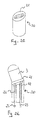
- substantially tubular elements 20 (shown in Figures 2c, 2d) are used, each provided with an upper surface 21 set at the aforementioned angles of ⁇ v /2 and ⁇ H /2 and having the LEDs 3 mounted thereon.
- the tubular elements 20 may have a cross-section whatever, e.g. a circular cross-sectional shape.
- the elements 20 are provided with sockets 22 for the rheophores 23 of the LEDs 3 and are secured on the holding/supply plate 6 by the same rheophores, which are soldered to the plate.
- the illuminating assemblies 2a, 2b are mounted on the holding plate 6 at an inclined position relative to one only of the reference planes XZ, YZ,
- the first and second lengths of each of the optical emission paths 100a, 100b are set at the angles of ⁇ v /2 ( ⁇ H /2) with respect to one of the first and second reference planes, the further inclination of the second path lengths by an angle of ⁇ H /2 ( ⁇ v /2) with respect to the other of the reference planes being obtained by placing an optical deflection prism 11 downstream (alternatively, upstream) of each diaphragm 4.
- the optical prisms 11 are made of a plastics material and may be placed, for example, between the LEDs 3 and the converging lenses 5.
- they may be integral with their respective converging lenses 5 to form a single optical element obtained, preferably, by a molding process of plastics material.
- the device of this invention comprises only two groups of illuminating assemblies 2a, 2b mounted on the holding plate 6 at an angle with respect to the second reference plane YZ.
- a V-like light guide 12 is mounted downstream of each LED 3 for providing a pair of optical emission paths 100 which are inclined, relative to the axis Z, by an angle of ⁇ H /2 on the second reference plane YZ.
- upstream of the light guide 12 there are defined two optical emission paths set at the inclination angles of ⁇ v /2 relative to the axis Z on the first reference plane XZ, while defined downstream of the guides 12 are four optical emission paths 100 which are further inclined relative to the axis Z by the angles of ⁇ H /2 on the second reference plane YZ.
- the device of this invention also includes means (not shown) of picking up, along a receiving path substantially coincident with the axis Z, and storing and processing the shaped image diffused from the illuminated end portions of the reading zone, in order to determine the distance and the orientation of the latter with respect to the device.
- these means comprise a lens (not shown) which is mounted in a respective seat 13 formed in the mounting plate 10 and has an optical axis coaxial with the optical axis Z.
- the lens picks up the light diffused from the illuminated end portions of the reading zone and projects it onto an appropriate sensing means (e.g. a CCD sensor).
- the last-mentioned means generate an image of the reading zone, and hence also of the shaped patterns, and are operatively associated with a processing means for the image acquired by the sensing means for calculating the distance and the orientation of the reading zone with respect to the device 1.
- the distance and orientation of the reading zone with respect to the device 1 are calculated by means of a simple calculation software, as functions of structural parameters of the device and optical parameters of the light emission and receiving paths. These parameters include the size of the diaphragms 4, the distance between the sensing means and the diaphragms 4, the distance between the lens and the converging lenses 5, and the size of the image acquired by the sensing means.
- the aiming device of this invention can advantageously be mounted inside an optical reader for properly pointing the reader at an area containing information to be read, so as to optimize subsequent information reading operations.
- This information may be, for example, a code (e.g. a bar code, two-dimensional code, or the like) arranged to univocally identify the objects carrying it, or handwriting such as a signature to be recognized, etc..
- the operator aims the reader at an area containing the optical information to be read.
- the operator By depressing a suitable control key, the operator causes the LEDs 3 to emit light beams which are suitably shaped through the diaphragms 4, picked up on the converging lenses 5, and projected onto the reading zone, where a read rectangle becomes displayed.
- the operator shifts the reader around until the information to be read is framed within the rectangle. At this point, the operator initiates the image acquisition and reading operations.
- the light diffused from the illuminated end portions of the reading zone is picked up on the receiving lens and projected onto the sensing means to generate an image of the reading area, and hence of the shaped patterns.
- These images are processed through calculation software to calculate the distance and orientation of the reading area relative to the reader, according to the size of the diaphragms 4, the distance between the sensing means and the diaphragms 4, the distance between the lens and the converging lenses 5, and the size of the image picked up on the sensing means.
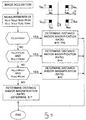
- the pattern images are acquired on the sensing means, their above-defined horizontal and vertical dimensions are calculated, and the horizontal dimensions of the top right and bottom left patterns are tested to be the same. If such test has a positive result, it means that the reading zone is perpendicular to the optical axis Z of the device, and therefore, the distance is calculated next and, by comparison with the dimensions of the projected patterns, a magnification ratio of the device of the present invention can also be calculated.
- Dr K ⁇ D L 2 - K
- K L 0 S ' r S ' p
- D r is the distance from the reading zone to the plane of the lens
- L 2 is the size, in pixels, of the pattern image onto the sensing means (and hence, any of the above dimensions H and V)
- L 0 is the size of the diaphragm
- S r ' is the distance between the main image plane of the lens and the sensing means
- S p ' is the distance between the diaphragm and the main image plane of the converging lens
- ⁇ D is the distance between the main image plane of the lens and the converging lens.
- the main image plane of the lens (and converging lens) is a known optical characteristic typical of each lens (and converging lens)
- the designing criterion will, therefore, be that of maximizing the value of ⁇ D, in order to enhance the sensitiveness of the method consistently with a compact size for the device.
- the above test has a negative result, it is tested if the horizontal dimension of the bottom left pattern is equal to that of the bottom right pattern, and the horizontal dimension of the top left pattern is equal to that of the top right pattern. If both the tests have positive results, additionally to determining the distance and/or the magnification ratio, the angle of rotation of the reading zone relative to the axis X, and accordingly, a distortion factor due to that rotation, can be determined. If one of the above mentioned tests has a negative result, a test is carried out to verify whether the horizontal dimension of the bottom left pattern is equal to that of the top left pattern, and whether the horizontal dimension of the bottom right pattern is equal to that of the top right pattern.
- both the tests are successful, additionally to determining the distance and/or the magnification ratio, the angle of rotation of the reading zone relative to the axis Y, and hence a distortion factor due to that rotation, can be determined. If these tests also have negative results, it is an indication of the reading zone being oriented to present rotation both about the axis X and about the axis Y. Therefore, the relating rotation angles can be found, and the range and/or magnification ratio of the device calculated.
Landscapes
- Physics & Mathematics (AREA)
- General Physics & Mathematics (AREA)
- Optics & Photonics (AREA)
- Length Measuring Devices By Optical Means (AREA)
- Eye Examination Apparatus (AREA)
- Photometry And Measurement Of Optical Pulse Characteristics (AREA)
- Position Input By Displaying (AREA)
- Image Input (AREA)
- Character Input (AREA)
Claims (29)
- Dispositif optique pour viser selon un axe Z et indiquer visuellement une zone de lecture, comprenant au moins un ensemble d'illumination (2a,2b) actif sur une partie de zone de lecture selon un trajet d'émission optique (100a,100b), dans lequel cet au moins un ensemble d'illumination (2a,2b) comprend:caractérisé en ce que l'au moins un ensemble d'illumination (2a,2b) comprend en outre un diaphragme (4) interposé entre la source lumineuse (3) et la lentille convergente (5), ce diaphragme ayant une forme prédéterminée pour sélectionner une partie du faisceau lumineux généré par la source lumineuse (3), permettant ainsi la propagation de cette partie sélectionnée du faisceau lumineux et empêchant la propagation de la partie restante du faisceau lumineux.une source lumineuse (3) pour émettre un faisceau lumineux;une lentille convergente (5) pour collimater le faisceau lumineux émis et le projeter sur la partie de zone de lecture;
- Dispositif selon la revendication 1, dans lequel la lentille convergente (5) est positionnée à une distance convenable du diaphragme (4) de façon que la lumière conformée provenant du diaphragme (4) soit focalisée sur la partie de zone de lecture.
- Dispositif selon la revendication 1, comprenant au moins deux premiers ensembles d'illumination (2a) disposés symétriquement par rapport à l'axe de visée Z de façon que leurs trajets d'émission optique respectifs (100a) identifient une partie linéaire sur la zone de lecture.
- Dispositif selon la revendication 3, comprenant au moins deux seconds ensembles d'illumination (2b) disposés symétriquement par rapport à l'axe de visée Z de façon que leurs trajets d'émission optique respectifs (100b) identifient, conjointement avec les trajets optiques (100a) des premiers ensembles d'illumination (2a), une partie quadrangulaire sur la zone de lecture.
- Dispositif selon la revendication 1, dans lequel la source lumineuse (3) génère un faisceau optique incliné par rapport à un premier et un second plan de référence XZ,YZ s'étendant perpendiculairement l'un à l'autre et se coupant l'un l'autre selon l'axe de visée Z.
- Dispositif selon les revendications 3 et 5, dans lequel les trajets optiques (100a) des premiers ensembles d'illumination (2a) sont disposés, par rapport à l'axe Z, à un angle de +v/2 et -v/2, respectivement, sur le premier plan de référence XZ, et à un angle de +H/2 et -H/2, respectivement, sur le second plan de référence YZ.
- Dispositif selon les revendications 4 et 5, dans lequel les trajets optiques (100b) des seconds ensembles d'illumination (2b) sont disposés, par rapport à l'axe Z, à un angle de +v/2 et -v/2, respectivement, sur le premier plan de référence XZ, et à un angle de +H/2 et -H/2, respectivement, sur le second plan de référence YZ.
- Dispositif selon l'une quelconque des revendications 6 ou 7, comprenant au moins un élément sensiblement tubulaire (20) ayant une surface supérieure inclinée (21) pour recevoir la source lumineuse (3) de façon que le trajet optique (100a,100b) de l'ensemble d'illumination (2a,2b) soit incliné à des angles de ±v/2 et ±H/2 par rapport à l'axe Z.
- Dispositif selon la revendication 1, comprenant en outre au moins un prisme de déviation optique (9) disposé sur le trajet d'émission optique (100a,100b).
- Dispositif selon l'une quelconque des revendications 6 ou 7, dans lequel chaque trajet d'émission optique (100a,100b) des ensembles d'illumination (2a,2b) comprend une première longueur de trajet disposée, par rapport à l'axe Z, à un angle de +v/2 et -v/2, respectivement, sur le premier plan de référence XZ, et une seconde longueur de trajet disposée, par rapport à l'axe Z, à un angle de +v/2 et -v/2, respectivement, sur le premier plan de référence XZ, et à un angle de +H/2 et -H/2, respectivement, sur le second plan de référence YZ.
- Dispositif selon l'une quelconque des revendications 6 ou 7, dans lequel chaque trajet d'émission optique (100a,100b) des ensembles d'illumination (2a,2b) comprend une première longueur de trajet disposée, par rapport à l'axe Z, à un angle de +H/2 et -H/2, respectivement, sur le second plan de référence YZ, et une seconde longueur de trajet disposée, par rapport à l'axe Z, à un angle de +H/2 et -H/2, respectivement, sur le second plan de référence YZ, et à un angle de +v/2 et -v/2, respectivement, sur le premier plan de référence YZ.
- Dispositif selon les revendications 9 et 10, dans lequel le prisme de déviation optique (9) a pour effet de dévier les secondes longueurs de trajet suivant des angles ±H/2.
- Dispositif selon les revendications 9 et 11, dans lequel le prisme de déviation optique (9) a pour effet de dévier les secondes longueurs de trajet suivant des angles ±v/2.
- Dispositif selon l'une quelconque des revendications 6 ou 7, dans lequel chaque trajet d'émission optique (100a,100b) des ensembles d'illumination (2a,2b) comprend une première longueur de trajet sensiblement parallèle à l'axe de visée Z, et une seconde longueur de trajet disposée, par rapport à l'axe Z, à un angle de +v/2 et -v/2, respectivement, sur le premier plan de référence XZ, et à un angle de +H/2 et -H/2, respectivement, sur le second plan de référence YZ.
- Dispositif selon la revendication 14, comprenant une paire de prismes de déviation optique (9) disposés sur chaque trajet d'émission optique (100a, 100b), et ayant pour effet de dévier les secondes longueurs de trajet suivant des angles ±H/2 et ±v/2.
- Dispositif selon la revendication 14, comprenant un seul prisme de déviation optique (9) disposé sur chaque trajet d'émission optique (100a,100b) en aval de la lentille convergente (5) et ayant pour effet de dévier les secondes longueurs de trajet suivant des angles ±H/2 et ±v/2.
- Dispositif selon la revendication 15, dans lequel les prismes optiques (9) de chaque paire de prismes optiques (9) sont de construction intégrale et sont placés en aval de la lentille convergente (5) sur le trajet d'émission optique (100a,100b).
- Dispositif selon la revendication 15, dans lequel les primes optiques (9) de chaque paire de prismes optiques (9) sont formés d'un seul tenant avec les prismes optiques (9) de la paire de prismes (9) située du même côté par rapport au second plan de référence YZ.
- Dispositif selon les revendications 17 et 18, dans lequel les paires de prismes optiques (9) situées sur des côtés opposés par rapport au second plan de référence YZ sont mutuellement associées par une plaque de montage.
- Dispositif selon la revendication 1, comprenant en outre un élément tubulaire (7a,7b) associé à une plaque de maintien et d'alimentation (6) pour la source lumineuse (3) et adapté à isoler la lumière émise par la source (3) et maintenir le diaphragme (4) et la lentille convergente (5).
- Dispositif selon la revendication 1, dans lequel l'ensemble d'illumination (2a,2b) comprend un guide lumineux en V (12) disposé sur le trajet d'émission (100) entre la source lumineuse (3) et la lentille convergente (5) et ayant pour effet de générer une paire de trajets optiques (100) respectivement disposés, par rapport à l'axe Z, à un angle de ±H/2 sur un second plan de référence YZ.
- Dispositif selon la revendication 1, comprenant en outre des moyens pour déterminer la distance de la zone de lecture par rapport au dispositif (1).
- Dispositif selon la revendication 1, comprenant en outre des moyens pour déterminer l'orientation de la zone de lecture par rapport au dispositif (1).
- Dispositif selon les revendications 22 et 23, dans lequel les moyens pour déterminer lesdites distance et orientation de la zone de lecture comprennent:une lentille pour collecter la lumière diffusée à partir de la partie illuminée de la zone de lecture;des moyens pour capter l'image de la lumière diffusée à partir de la zone de lecture et collectée sur la lentille;des moyens pour traiter l'image acquise par les moyens capteurs pour calculer la distance et l'orientation de la zone de lecture suivant la taille du diaphragme (4), la distance entre les moyens capteurs et le diaphragme (4), la distance entre la lentille et la lentille convergente (5), et la taille de l'image acquise par les moyens capteurs.
- Appareil optique pour lire des informations, caractérisé en ce qu'il comprend un dispositif (1) tel que revendiqué dans la revendication 1.
- Procédé pour viser et indiquer visuellement une zone de lecture comprenant les étapes suivantes:caractérisé par l'étape suivante:générer au moyen d'une source lumineuse (3) au moins un faisceau lumineux pour illuminer une partie de la zone de lecture selon un trajet d'émission (100a,100b);collimater au moyen d'une lentille convergente (5) le faisceau lumineux émis et le projeter sur la partie de la zone de lecture,sélectionner, au moyen d'un diaphragme de forme (4) interposé entre la source lumineuse (3) et la lentille convergente (5), une partie du faisceau lumineux généré par la source lumineuse (3), permettant ainsi la propagation de ladite partie sélectionnée du faisceau lumineux et empêchant la propagation de la partie restante du faisceau lumineux.
- Procédé selon la revendication 26, comprenant l'étape de déterminer la distance de la zone de lecture.
- Procédé selon la revendication 26, comprenant l'étape de déterminer l'orientation de la zone de lecture.
- Procédé selon les revendications 27 et 28, dans lequel les étapes de déterminer la distance et l'orientation de la zone de lecture comprennent les étapes suivantes:collecter, sur une lentille réceptrice, le faisceau lumineux diffusé à partir de la partie illuminée de la zone de lecture;acquérir, sur des moyens capteurs, l'image de la lumière diffusée à partir de la zone de lecture et collectée sur la lentille réceptrice;traiter l'image acquise pour calculer la distance et l'orientation de la zone de lecture suivant la taille du diaphragme (4), la distance entre les moyens capteurs et le diaphragme (4), la distance entre la lentille et la lentille convergente (5), et la taille de l'image collectée sur les moyens capteurs.
Priority Applications (6)
| Application Number | Priority Date | Filing Date | Title |
|---|---|---|---|
| AT98830656T ATE211830T1 (de) | 1998-10-30 | 1998-10-30 | Optisches gerät und verfahren zum anvisieren und visuellen anzeigen eines auslesebereichs |
| DE69803459T DE69803459T2 (de) | 1998-10-30 | 1998-10-30 | Optisches Gerät und Verfahren zum Anvisieren und visuellen Anzeigen eines Auslesebereichs |
| ES98830656T ES2171007T3 (es) | 1998-10-30 | 1998-10-30 | Dispositivo optico y procedimiento para apuntar y marcar visualmente un area de lectura. |
| EP98830656A EP0997760B1 (fr) | 1998-10-30 | 1998-10-30 | Dispositif optique et procédé pour le visé et l'indication visuelle d'un champs de lecture |
| JP11306028A JP2000148901A (ja) | 1998-10-30 | 1999-10-27 | 読取り領域を照準および可視表示する光学装置およびその方法 |
| US10/963,723 US7075663B2 (en) | 1998-10-30 | 2004-10-14 | Optical device and a method for aiming and visually indicating a reading area |
Applications Claiming Priority (1)
| Application Number | Priority Date | Filing Date | Title |
|---|---|---|---|
| EP98830656A EP0997760B1 (fr) | 1998-10-30 | 1998-10-30 | Dispositif optique et procédé pour le visé et l'indication visuelle d'un champs de lecture |
Publications (2)
| Publication Number | Publication Date |
|---|---|
| EP0997760A1 EP0997760A1 (fr) | 2000-05-03 |
| EP0997760B1 true EP0997760B1 (fr) | 2002-01-09 |
Family
ID=8236860
Family Applications (1)
| Application Number | Title | Priority Date | Filing Date |
|---|---|---|---|
| EP98830656A Expired - Lifetime EP0997760B1 (fr) | 1998-10-30 | 1998-10-30 | Dispositif optique et procédé pour le visé et l'indication visuelle d'un champs de lecture |
Country Status (6)
| Country | Link |
|---|---|
| US (1) | US7075663B2 (fr) |
| EP (1) | EP0997760B1 (fr) |
| JP (1) | JP2000148901A (fr) |
| AT (1) | ATE211830T1 (fr) |
| DE (1) | DE69803459T2 (fr) |
| ES (1) | ES2171007T3 (fr) |
Families Citing this family (18)
| Publication number | Priority date | Publication date | Assignee | Title |
|---|---|---|---|---|
| US7270274B2 (en) * | 1999-10-04 | 2007-09-18 | Hand Held Products, Inc. | Imaging module comprising support post for optical reader |
| EP1172756B1 (fr) * | 2000-07-11 | 2009-02-18 | Datalogic S.P.A. | Dispositif et élément optique pour la visée et l'indication visuelle d'un champs de lecture d'un lecteur de l'information codée |
| US7311260B2 (en) * | 2002-01-18 | 2007-12-25 | Microscan Systems Incorporated | Camera positioning and confirmation feedback system |
| US7957554B1 (en) | 2002-12-31 | 2011-06-07 | Cognex Technology And Investment Corporation | Method and apparatus for human interface to a machine vision system |
| CN100388299C (zh) * | 2004-08-19 | 2008-05-14 | 电装波动株式会社 | 光学信息读取装置 |
| JP4169001B2 (ja) | 2004-08-19 | 2008-10-22 | 株式会社デンソーウェーブ | 光学情報読取装置 |
| US8181878B2 (en) | 2006-01-25 | 2012-05-22 | Cognex Technology And Investment Corporation | Method and apparatus for providing a focus indication for optical imaging of visual codes |
| US8181877B2 (en) | 2006-12-18 | 2012-05-22 | Datalogic Scanning Group S.R.L. | Aiming device |
| US8302864B2 (en) | 2007-12-28 | 2012-11-06 | Cognex Corporation | Method and apparatus using aiming pattern for machine vision training |
| US8646689B2 (en) | 2007-12-28 | 2014-02-11 | Cognex Corporation | Deformable light pattern for machine vision system |
| US8134116B2 (en) | 2009-01-12 | 2012-03-13 | Cognex Corporation | Modular focus system for image based code readers |
| JP5310422B2 (ja) * | 2009-09-11 | 2013-10-09 | 株式会社デンソーウェーブ | 光学的情報読取装置 |
| US11366284B2 (en) | 2011-11-22 | 2022-06-21 | Cognex Corporation | Vision system camera with mount for multiple lens types and lens module for the same |
| US10498933B2 (en) | 2011-11-22 | 2019-12-03 | Cognex Corporation | Camera system with exchangeable illumination assembly |
| US8947590B2 (en) | 2011-11-22 | 2015-02-03 | Cognex Corporation | Vision system camera with mount for multiple lens types |
| US9746636B2 (en) | 2012-10-19 | 2017-08-29 | Cognex Corporation | Carrier frame and circuit board for an electronic device |
| US10268854B1 (en) | 2018-04-13 | 2019-04-23 | Zebra Technologies Corporation | Illumination assemblies for use in barcode readers and devices and methods associated therewith |
| US12554952B1 (en) | 2024-11-23 | 2026-02-17 | Datalogic Usa, Inc. | Systems and methods for higher scan rates of human aimed scanners in various environments |
Family Cites Families (32)
| Publication number | Priority date | Publication date | Assignee | Title |
|---|---|---|---|---|
| US3010019A (en) | 1958-11-10 | 1961-11-21 | Sohst Walter | Optical aiming device |
| DE1673846B2 (de) | 1968-02-20 | 1976-09-09 | Betz, Hans-Dieter, Dr., 6800 Mannheim | Anordnung zum optischen ausrichten von raeumlich getrennten elementen mit hilfe eines laserstrahles |
| US3853227A (en) | 1972-11-15 | 1974-12-10 | G Filipowski | Hanging file assembly |
| FR2339832A1 (fr) * | 1976-01-27 | 1977-08-26 | Emile Stauff | Perfectionnements apportes au guidage d'un projectile vers son objectif |
| FR2337326A1 (fr) * | 1975-12-29 | 1977-07-29 | Realisations Electronique Et | Appareil d'observation et de visee, notamment sur vehicule |
| GB8602605D0 (en) | 1986-02-03 | 1986-03-12 | Short Brothers Ltd | Mirror assembly |
| DE3613513A1 (de) | 1986-04-22 | 1987-10-29 | Walter Gehmann | Dioptervisier |
| DE3615714A1 (de) | 1986-05-09 | 1987-11-12 | Bernhard Dr Wolf | Mikrotom |
| US4816659A (en) | 1987-10-13 | 1989-03-28 | Control Module Inc. | Bar code reader head |
| US5052790A (en) * | 1987-12-18 | 1991-10-01 | Edwards Optical Corporation | Telemicroscopic apparatus for sighting and bi-level viewing |
| US5280161A (en) | 1988-11-18 | 1994-01-18 | West Electric Company, Ltd. | Apparatus for optically reading a bar code |
| US5010241A (en) * | 1989-01-12 | 1991-04-23 | Hewlett-Packard Company | Sensor array and illumination system for a large depth-of-field bar code scanner |
| FR2673738A1 (fr) * | 1991-03-05 | 1992-09-11 | Digital Vision | Dispositif optoelectronique d'acquisition d'images lineaires, notamment de codes a barres. |
| EP0537431B1 (fr) | 1991-10-14 | 1997-05-28 | Mars, Incorporated | Dispositif pour la reconnaissance optique de documents |
| JPH06274668A (ja) * | 1991-10-21 | 1994-09-30 | Taiyo Eretsukusu Kk | コード読取器 |
| FR2700404B1 (fr) | 1993-01-11 | 1995-03-31 | Reflexion Plus | Lecteur de vignettes de codes à barres, du type dit "à main" à profondeur de champ accrue. |
| US5513000A (en) * | 1993-07-26 | 1996-04-30 | Princeton Scientific Instruments Inc. | Autocollimator |
| JPH07193682A (ja) * | 1993-12-27 | 1995-07-28 | Nec Corp | 読取り装置 |
| US5491546A (en) * | 1994-02-17 | 1996-02-13 | Wascher; Rick R. | Laser assisted telescopic target sighting system and method |
| US5886332A (en) | 1994-04-19 | 1999-03-23 | Geo Labs, Inc. | Beam shaping system with surface treated lens and methods for making same |
| JP3531014B2 (ja) | 1994-06-22 | 2004-05-24 | 株式会社トプコン | レーザ照準装置 |
| US5814803A (en) * | 1994-12-23 | 1998-09-29 | Spectra-Physics Scanning Systems, Inc. | Image reader with multi-focus lens |
| US5929444A (en) * | 1995-01-31 | 1999-07-27 | Hewlett-Packard Company | Aiming device using radiated energy |
| US5600121A (en) * | 1995-03-20 | 1997-02-04 | Symbol Technologies, Inc. | Optical reader with independent triggering and graphical user interface |
| JPH0950475A (ja) * | 1995-08-08 | 1997-02-18 | Hitachi Maxell Ltd | マーク検出方法および装置 |
| US5738595A (en) * | 1995-10-16 | 1998-04-14 | Carney; William P. | Laser aiming device |
| CA2169865C (fr) | 1996-02-20 | 2007-07-03 | Vitold A. Khvostov | Detecteur de rayons lumineux reflechis pour dispositifs de balayage |
| JPH09247362A (ja) * | 1996-03-06 | 1997-09-19 | Sony Corp | 画像入力装置 |
| US5793033A (en) * | 1996-03-29 | 1998-08-11 | Metanetics Corporation | Portable data collection device with viewing assembly |
| DE19710724C2 (de) | 1997-03-14 | 2002-09-26 | Sick Ag | Optoelektronischer Sensor |
| US5979760A (en) | 1997-06-27 | 1999-11-09 | Accu-Sort Systems, Inc. | Scanner with linear actuator based lens positioning system |
| JP3347035B2 (ja) * | 1997-10-29 | 2002-11-20 | 日立建機株式会社 | 光学式偏角測定装置及び地中掘進機の位置計測装置 |
-
1998
- 1998-10-30 AT AT98830656T patent/ATE211830T1/de not_active IP Right Cessation
- 1998-10-30 ES ES98830656T patent/ES2171007T3/es not_active Expired - Lifetime
- 1998-10-30 EP EP98830656A patent/EP0997760B1/fr not_active Expired - Lifetime
- 1998-10-30 DE DE69803459T patent/DE69803459T2/de not_active Expired - Lifetime
-
1999
- 1999-10-27 JP JP11306028A patent/JP2000148901A/ja active Pending
-
2004
- 2004-10-14 US US10/963,723 patent/US7075663B2/en not_active Expired - Lifetime
Also Published As
| Publication number | Publication date |
|---|---|
| US7075663B2 (en) | 2006-07-11 |
| US20050046827A1 (en) | 2005-03-03 |
| ES2171007T3 (es) | 2002-08-16 |
| DE69803459D1 (de) | 2002-02-28 |
| EP0997760A1 (fr) | 2000-05-03 |
| ATE211830T1 (de) | 2002-01-15 |
| JP2000148901A (ja) | 2000-05-30 |
| DE69803459T2 (de) | 2003-02-13 |
Similar Documents
| Publication | Publication Date | Title |
|---|---|---|
| US7075663B2 (en) | Optical device and a method for aiming and visually indicating a reading area | |
| EP1164536B1 (fr) | Appareil de lecture d'un code optique | |
| US6060722A (en) | Optical reader having illumination assembly including improved aiming pattern generator | |
| US5684290A (en) | Symbology reader illumination system | |
| EP1245926B1 (fr) | Dispositif de visée laser comportant un dispositif de mesure d'inclinaison | |
| CN101730896B (zh) | 视觉系统、安装视觉系统的方法和制造视觉系统的方法 | |
| EP0137966A2 (fr) | Dispositif optique pour détecter des symboles codés | |
| US5910844A (en) | Dynamic three dimensional vision inspection system | |
| US6124585A (en) | Apparatus for measuring the reflectance of strips having non-uniform color | |
| US7311260B2 (en) | Camera positioning and confirmation feedback system | |
| CN110297303A (zh) | 用于在底座内对准透镜组件的设备系统和方法 | |
| KR20020066378A (ko) | 안경 렌즈 또는 콘택트 렌즈의 특성 측정용 렌즈 미터 | |
| US6359694B1 (en) | Method and device for identifying the position of an electrical component or terminals thereof, and equipping head employing same | |
| US5572368A (en) | Light projecting device with cylindrical lens | |
| EP1193640B1 (fr) | Dispositif de lecture de données optiques | |
| KR100810587B1 (ko) | 현미경 | |
| US7456941B2 (en) | Measuring device for measuring the refraction properties of optical lenses | |
| US20060238747A1 (en) | Measuring device for measuring the refraction properties of optical lenses | |
| KR102581986B1 (ko) | 릴레이티브 액티브 얼라인 장치 | |
| US5099583A (en) | Incremental measuring system | |
| CN218068287U (zh) | 光学调节装置及光学系统 | |
| EP0606770B1 (fr) | Membre à point de mesure pour mesures optiques | |
| US8181877B2 (en) | Aiming device | |
| JP2005504454A (ja) | 改良された照明器を有するカメラ | |
| US6582090B1 (en) | Method and apparatus for illuminating leads of a component |
Legal Events
| Date | Code | Title | Description |
|---|---|---|---|
| PUAI | Public reference made under article 153(3) epc to a published international application that has entered the european phase |
Free format text: ORIGINAL CODE: 0009012 |
|
| AK | Designated contracting states |
Kind code of ref document: A1 Designated state(s): AT BE CH DE DK ES FR GB IT LI NL PT SE |
|
| AX | Request for extension of the european patent |
Free format text: AL;LT;LV;MK;RO;SI |
|
| 17P | Request for examination filed |
Effective date: 20000415 |
|
| 17Q | First examination report despatched |
Effective date: 20000718 |
|
| AKX | Designation fees paid |
Free format text: AT BE CH DE DK ES FR GB IT LI NL PT SE |
|
| GRAG | Despatch of communication of intention to grant |
Free format text: ORIGINAL CODE: EPIDOS AGRA |
|
| GRAG | Despatch of communication of intention to grant |
Free format text: ORIGINAL CODE: EPIDOS AGRA |
|
| GRAG | Despatch of communication of intention to grant |
Free format text: ORIGINAL CODE: EPIDOS AGRA |
|
| GRAH | Despatch of communication of intention to grant a patent |
Free format text: ORIGINAL CODE: EPIDOS IGRA |
|
| GRAH | Despatch of communication of intention to grant a patent |
Free format text: ORIGINAL CODE: EPIDOS IGRA |
|
| GRAA | (expected) grant |
Free format text: ORIGINAL CODE: 0009210 |
|
| REG | Reference to a national code |
Ref country code: GB Ref legal event code: IF02 |
|
| AK | Designated contracting states |
Kind code of ref document: B1 Designated state(s): AT BE CH DE DK ES FR GB IT LI NL PT SE |
|
| PG25 | Lapsed in a contracting state [announced via postgrant information from national office to epo] |
Ref country code: NL Free format text: LAPSE BECAUSE OF FAILURE TO SUBMIT A TRANSLATION OF THE DESCRIPTION OR TO PAY THE FEE WITHIN THE PRESCRIBED TIME-LIMIT Effective date: 20020109 Ref country code: LI Free format text: LAPSE BECAUSE OF FAILURE TO SUBMIT A TRANSLATION OF THE DESCRIPTION OR TO PAY THE FEE WITHIN THE PRESCRIBED TIME-LIMIT Effective date: 20020109 Ref country code: CH Free format text: LAPSE BECAUSE OF FAILURE TO SUBMIT A TRANSLATION OF THE DESCRIPTION OR TO PAY THE FEE WITHIN THE PRESCRIBED TIME-LIMIT Effective date: 20020109 Ref country code: BE Free format text: LAPSE BECAUSE OF FAILURE TO SUBMIT A TRANSLATION OF THE DESCRIPTION OR TO PAY THE FEE WITHIN THE PRESCRIBED TIME-LIMIT Effective date: 20020109 Ref country code: AT Free format text: LAPSE BECAUSE OF FAILURE TO SUBMIT A TRANSLATION OF THE DESCRIPTION OR TO PAY THE FEE WITHIN THE PRESCRIBED TIME-LIMIT Effective date: 20020109 |
|
| REF | Corresponds to: |
Ref document number: 211830 Country of ref document: AT Date of ref document: 20020115 Kind code of ref document: T |
|
| REG | Reference to a national code |
Ref country code: CH Ref legal event code: EP |
|
| REF | Corresponds to: |
Ref document number: 69803459 Country of ref document: DE Date of ref document: 20020228 |
|
| PG25 | Lapsed in a contracting state [announced via postgrant information from national office to epo] |
Ref country code: SE Free format text: LAPSE BECAUSE OF FAILURE TO SUBMIT A TRANSLATION OF THE DESCRIPTION OR TO PAY THE FEE WITHIN THE PRESCRIBED TIME-LIMIT Effective date: 20020409 Ref country code: PT Free format text: LAPSE BECAUSE OF FAILURE TO SUBMIT A TRANSLATION OF THE DESCRIPTION OR TO PAY THE FEE WITHIN THE PRESCRIBED TIME-LIMIT Effective date: 20020409 Ref country code: DK Free format text: LAPSE BECAUSE OF FAILURE TO SUBMIT A TRANSLATION OF THE DESCRIPTION OR TO PAY THE FEE WITHIN THE PRESCRIBED TIME-LIMIT Effective date: 20020409 |
|
| NLV1 | Nl: lapsed or annulled due to failure to fulfill the requirements of art. 29p and 29m of the patents act | ||
| ET | Fr: translation filed | ||
| REG | Reference to a national code |
Ref country code: CH Ref legal event code: PL |
|
| REG | Reference to a national code |
Ref country code: ES Ref legal event code: FG2A Ref document number: 2171007 Country of ref document: ES Kind code of ref document: T3 |
|
| PLBE | No opposition filed within time limit |
Free format text: ORIGINAL CODE: 0009261 |
|
| STAA | Information on the status of an ep patent application or granted ep patent |
Free format text: STATUS: NO OPPOSITION FILED WITHIN TIME LIMIT |
|
| 26N | No opposition filed | ||
| NLV1 | Nl: lapsed or annulled due to failure to fulfill the requirements of art. 29p and 29m of the patents act | ||
| REG | Reference to a national code |
Ref country code: FR Ref legal event code: PLFP Year of fee payment: 18 |
|
| REG | Reference to a national code |
Ref country code: FR Ref legal event code: PLFP Year of fee payment: 19 |
|
| REG | Reference to a national code |
Ref country code: FR Ref legal event code: PLFP Year of fee payment: 20 |
|
| PGFP | Annual fee paid to national office [announced via postgrant information from national office to epo] |
Ref country code: FR Payment date: 20171024 Year of fee payment: 20 Ref country code: DE Payment date: 20171019 Year of fee payment: 20 |
|
| PGFP | Annual fee paid to national office [announced via postgrant information from national office to epo] |
Ref country code: GB Payment date: 20171019 Year of fee payment: 20 Ref country code: ES Payment date: 20171121 Year of fee payment: 20 Ref country code: IT Payment date: 20171023 Year of fee payment: 20 |
|
| REG | Reference to a national code |
Ref country code: DE Ref legal event code: R071 Ref document number: 69803459 Country of ref document: DE |
|
| REG | Reference to a national code |
Ref country code: GB Ref legal event code: PE20 Expiry date: 20181029 |
|
| PG25 | Lapsed in a contracting state [announced via postgrant information from national office to epo] |
Ref country code: GB Free format text: LAPSE BECAUSE OF EXPIRATION OF PROTECTION Effective date: 20181029 |
|
| REG | Reference to a national code |
Ref country code: ES Ref legal event code: FD2A Effective date: 20220128 |
|
| PG25 | Lapsed in a contracting state [announced via postgrant information from national office to epo] |
Ref country code: ES Free format text: LAPSE BECAUSE OF EXPIRATION OF PROTECTION Effective date: 20181031 |