EP0997987A2 - Schwimmend gelagerter Verbinder zum Verbinden elektrischer Baugruppen - Google Patents
Schwimmend gelagerter Verbinder zum Verbinden elektrischer Baugruppen Download PDFInfo
- Publication number
- EP0997987A2 EP0997987A2 EP99121470A EP99121470A EP0997987A2 EP 0997987 A2 EP0997987 A2 EP 0997987A2 EP 99121470 A EP99121470 A EP 99121470A EP 99121470 A EP99121470 A EP 99121470A EP 0997987 A2 EP0997987 A2 EP 0997987A2
- Authority
- EP
- European Patent Office
- Prior art keywords
- plug
- connector
- receptacle
- connectors
- mating
- Prior art date
- Legal status (The legal status is an assumption and is not a legal conclusion. Google has not performed a legal analysis and makes no representation as to the accuracy of the status listed.)
- Withdrawn
Links
Images

Classifications
-
- H—ELECTRICITY
- H01—ELECTRIC ELEMENTS
- H01R—ELECTRICALLY-CONDUCTIVE CONNECTIONS; STRUCTURAL ASSOCIATIONS OF A PLURALITY OF MUTUALLY-INSULATED ELECTRICAL CONNECTING ELEMENTS; COUPLING DEVICES; CURRENT COLLECTORS
- H01R13/00—Details of coupling devices of the kinds covered by groups H01R12/70 or H01R24/00 - H01R33/00
- H01R13/62—Means for facilitating engagement or disengagement of coupling parts or for holding them in engagement
- H01R13/629—Additional means for facilitating engagement or disengagement of coupling parts, e.g. aligning or guiding means, levers, gas pressure electrical locking indicators, manufacturing tolerances
- H01R13/631—Additional means for facilitating engagement or disengagement of coupling parts, e.g. aligning or guiding means, levers, gas pressure electrical locking indicators, manufacturing tolerances for engagement only
- H01R13/6315—Additional means for facilitating engagement or disengagement of coupling parts, e.g. aligning or guiding means, levers, gas pressure electrical locking indicators, manufacturing tolerances for engagement only allowing relative movement between coupling parts, e.g. floating connection
Definitions
- This invention generally relates to the art of electrical connectors and, particularly, to an electrical connector assembly which provides for floating movement between a pair of mating connectors, such as connectors which are mounted to printed circuit boards or other substrates.
- connector assemblies which include male and female or plug and receptacle connectors which are designed to be mated in confronting relation.
- the connectors are movably mated together and, when mated, the connectors are rigidly coupled and cannot move relative to each other. Therefore, any vibrations or extraneous impacts applied to one of the connectors is transmitted to the other connector.
- the telephone in a portable telephone assembly, the telephone may be coupled to an associated battery through a pair of mating connectors, and the telephone and battery, in turn, may be mounted to a pair of circuit boards or substrates. If the telephone is inadvertently dropped and strikes the floor or ground, the impact may cause a malfunction or damage to electronic components mounted on the circuit boards on which the mating connectors are fixed. Therefore, it is desirable to provide some form of relative floating movement between the mating connectors, and this has become increasingly difficult with the increase in miniaturization or down-sizing of such electronic devices.
- the present invention is directed to solving these problems in a new construction of a pair of mating connectors having floating movement therebetween.
- An object, therefore, of the invention is to provide a new and improved electrical connector assembly which provides for floating movement between a pair of mated connectors.
- the assembly is a board-to-board electrical connector assembly.
- a plug connector is adapted for mounting on a first circuit board and includes a dielectric housing have a mating plug portion.
- a plurality of conductive terminals are mounted on the housing and have flexible contact portions located at the mating plug portion.
- a receptacle connector is adapted for mounting on a second circuit board and includes a dielectric housing having a mating receptacle portion for receiving the plug portion of the plug connector in a mating direction.
- a plurality of conductive terminals are mounted on the housing and have contact portions located in the receptacle portion for engaging the flexible contact portions of the terminals of the plug connector.
- the receptacle portion of the receptacle connector be larger than the plug portion of the plug connector in "x" and "y" directions transverse to the mating direction. This provides for floating movement between the connectors and, thereby, the circuit boards in the "x" and “y” directions.
- an open end of the receptacle portion is spaced from an abutment wall of the housing of the plug portion when the connectors are in mated positions. This provides floating movement between the connectors and, thereby, the circuit boards in the mating or "z" direction.
- At least one of the terminals of the plug connector includes a cantilevered spring beam extending generally in the mating direction of the plug connector toward the receptacle connector.
- a contact beam extends obliquely from a distal end of the cantilevered spring beam back over the spring beam.
- the contact beam extends at an angle to the mating direction such that a force vector from the contact beam against a terminal of the receptacle connector opposite the mating direction automatically causes the open end of the receptacle portion to be spaced from the abutment wall of the plug connector to allow for floating movement therebetween.
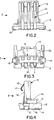
- Figure 1 shows a board-to-board electrical connector assembly 1 which includes a plug connector, generally designated 2, and a receptacle connector, generally designated 3.
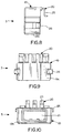
- the plug connector is adapted for mounting on a first circuit board 4 and is shown in greater detail in Figures 2-5.
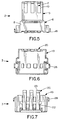
- the receptacle connector is adapted for mounting on a second circuit board 5 and is shown in greater detail in Figures 6-10.
- the circuit boards are disposed in two planes perpendicular to each other, with the connectors making required electrical connections therebetween.
- plug connector 2 includes a dielectric housing, generally designated 6, mounting three terminals, generally designated 7.
- the housing may be a one-piece structure unitarily molded of dielectric material such as plastic or the like.
- the housing includes a terminal retaining portion 8 and a mating plug portion 9.
- the plug portion has terminal-receiving slots 10, and the retaining portion has terminal mounting recesses 11 which open at a bottom face 8a of the housing.
- Terminal retaining portion 8 defines a top abutment wall 8b.
- Plug portion 9 has a front wall 9a.
- Each terminal 7 of plug connector 2 includes an inverted U-shaped engagement portion 12 which is inserted into a respective one of the bottom-opening recesses 11 in housing 6 by a press-fit to retain the terminal on the housing.
- Each terminal includes a base portion 13 and a solder tail 14 which extend in opposite directions from the distal ends of the legs which define U-shaped engagement portion 12. The solder tails of the terminals are connected, as by soldering, to appropriate circuit traces on circuit board 4.
- Each terminal includes a cantilevered spring beam 15 which extends upwardly and obliquely from base 13 into the respective terminal slot 10 in plug portion 9.
- a contact beam 16 extends obliquely from a distal end of spring beam 15 back over the spring beam. Contact beam 16 terminates in a rounded contact point 17.
- a pair of "fitting nails” 18 are fixed to housing 6 of plug connector 2 generally flush with solder tails 14 of terminals 7. These fitting nails are fabricated of metal material and are soldered to appropriate mounting pads on circuit board 4 when solder tails 14 are soldered to circuit traces on the board, to assist in fixing the plug connector to the board.
- receptacle connector 3 includes a dielectric housing 19 which is a one-piece structure unitarily molded of plastic material or the like.
- the housing mounts three terminals, generally designated 20.
- the housing defines a receptacle portion 21 for receiving plug portion 9 of plug connector 2 in a mating direction which can be called the "z" direction.
- housing 19 has a bottom surface 19a which defines an open end for receptacle portion 21.
- the receptacle portion has a front wall 21a.
- Each terminal 20 of receptacle connector 3 includes a base portion 22 which is disposed on top of housing 19.
- An L-shaped solder tail 23 extends downwardly from one end of base portion 22 for solder connector to an appropriate solder trace on circuit board 5.
- a contact beam 24 extends downwardly from the opposite end of base portion 22 through an opening 19b in housing 19 and into the open receptacle portion 21 of the housing.
- Each contact beam 24 has a contact surface 25 for engaging contact point 17 of a respective one of the terminals 7 of plug connector 2.
- a pair of "fitting nails” 26 also are mounted on housing 19 of receptacle connector 3. These fitting nails are fabricated of metal material and are located at a rear side 19c of the housing for soldering to appropriate mounting pads on circuit board 5 when solder tails 23 of terminals 20 are soldered to the circuit traces on the board.
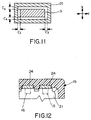
- receptacle portion 21 of receptacle connector 3 be larger than plug portion 9 of plug connector 2 in "x" and "y” directions which are transverse to the mating direction of the connectors.
- the clearances between the larger receptacle portion and the smaller plug portion in the "x" and “y” directions are indicated by the double-headed arrowed spaces C x and C y in Figure 11.
- spring beams 15 and contact beams 16 of terminals 7 of plug connector 6 will bias plug portion 9 to one side of receptacle portion 21 when the connectors are mated.
- Figure 11 clearly shows the dimensional clearances between the plug portion and the receptacle portion which allows for floating movement between the connectors and, thereby, between circuit boards 4 and 5 in the "x" and "y” directions generally transverse to the mating direction of the terminals.
- Figure 12 shows a pair of the contact beams 24 of terminals 20 of receptacle connector 3 in relation to a pair of the contact beams 16 of terminals 7 of plug connector 2, contact beams 16 being shown in phantom. It can be seen that the widths of contact beams 24 of the receptacle connector are significantly wider than the widths of contact beams 16 of the plug connector. In comparing the differences between the widths of the contact beams with the dimensional clearances C x and C y in Figure 11, it can be understood that there will be constant engagement between contact beams 24 and contact beams 16 regardless of the amount of floating movement between the two connectors.
- arrow 27 represents the direction of deflection of cantilevered spring beams 17 and contact beams 16 of terminals 7 of plug connector 2 when the connectors are mated. Because of the angle of contact beams 16 in particular, and in conjunction with the deflection of spring beams 15, a vertical force vector is created in the direction of arrow 28 from each contact beam 16 against contact beam 24 of terminal 20 of the receptacle connector. When the connectors are mated, open end 19a of receptacle portion 21 of the receptacle connector will confront and abut against abutment wall 8b of plug connector 2.
Landscapes
- Coupling Device And Connection With Printed Circuit (AREA)
- Details Of Connecting Devices For Male And Female Coupling (AREA)
- Connector Housings Or Holding Contact Members (AREA)
Applications Claiming Priority (2)
| Application Number | Priority Date | Filing Date | Title |
|---|---|---|---|
| JP32588598 | 1998-10-30 | ||
| JP10325885A JP2000138079A (ja) | 1998-10-30 | 1998-10-30 | 基板接続用コネクタ |
Publications (2)
| Publication Number | Publication Date |
|---|---|
| EP0997987A2 true EP0997987A2 (de) | 2000-05-03 |
| EP0997987A3 EP0997987A3 (de) | 2001-03-07 |
Family
ID=18181696
Family Applications (1)
| Application Number | Title | Priority Date | Filing Date |
|---|---|---|---|
| EP99121470A Withdrawn EP0997987A3 (de) | 1998-10-30 | 1999-10-28 | Schwimmend gelagerter Verbinder zum Verbinden elektrischer Baugruppen |
Country Status (3)
| Country | Link |
|---|---|
| US (1) | US6244883B1 (de) |
| EP (1) | EP0997987A3 (de) |
| JP (1) | JP2000138079A (de) |
Cited By (1)
| Publication number | Priority date | Publication date | Assignee | Title |
|---|---|---|---|---|
| CN105390847A (zh) * | 2014-08-28 | 2016-03-09 | 星电株式会社 | 连接器 |
Families Citing this family (7)
| Publication number | Priority date | Publication date | Assignee | Title |
|---|---|---|---|---|
| TW560753U (en) * | 2000-10-26 | 2003-11-01 | Hon Hai Prec Ind Co Ltd | Electrical connector |
| US6457998B1 (en) * | 2001-09-14 | 2002-10-01 | Hon Hasi Precision Ind. Co., Ltd. | Electrical connector with improved contacts |
| JP2005190923A (ja) * | 2003-12-26 | 2005-07-14 | Smk Corp | バッテリーコネクタ |
| US7074054B2 (en) * | 2004-08-06 | 2006-07-11 | Honeywell International Inc. | SMT terminal block |
| CN2772061Y (zh) * | 2005-02-04 | 2006-04-12 | 上海莫仕连接器有限公司 | 电连接器组件 |
| WO2019018239A1 (en) * | 2017-07-17 | 2019-01-24 | Jose Lopez | SELF-CLEANING ELECTRICAL CONTACT CONTACT DEVICE FOR SEMICONDUCTOR CONTACTS |
| JP7321878B2 (ja) * | 2019-10-15 | 2023-08-07 | ヒロセ電機株式会社 | コネクタ |
Family Cites Families (4)
| Publication number | Priority date | Publication date | Assignee | Title |
|---|---|---|---|---|
| DE69230913T2 (de) * | 1991-07-16 | 2000-12-07 | Berg Electronics Manufacturing B.V., S'-Hertogenbosch | Flachbau-, oberflächenmontierter Steckverbinder mit gekrümmten freitragendenKontaktfedern. |
| US5192232A (en) * | 1992-07-13 | 1993-03-09 | Molex Incorporated | Electrical connector system utilizing thin male terminals |
| US5310357A (en) * | 1993-02-22 | 1994-05-10 | Berg Technology, Inc. | Blade-like terminal having a passive latch |
| GB9425740D0 (en) * | 1994-12-20 | 1995-02-22 | Amp Gmbh | Anti-fretting terminal for PCB |
-
1998
- 1998-10-30 JP JP10325885A patent/JP2000138079A/ja active Pending
-
1999
- 1999-10-19 US US09/420,883 patent/US6244883B1/en not_active Expired - Fee Related
- 1999-10-28 EP EP99121470A patent/EP0997987A3/de not_active Withdrawn
Cited By (2)
| Publication number | Priority date | Publication date | Assignee | Title |
|---|---|---|---|---|
| CN105390847A (zh) * | 2014-08-28 | 2016-03-09 | 星电株式会社 | 连接器 |
| CN105390847B (zh) * | 2014-08-28 | 2018-12-07 | 星电株式会社 | 连接器 |
Also Published As
| Publication number | Publication date |
|---|---|
| JP2000138079A (ja) | 2000-05-16 |
| EP0997987A3 (de) | 2001-03-07 |
| US6244883B1 (en) | 2001-06-12 |
Similar Documents
| Publication | Publication Date | Title |
|---|---|---|
| EP0795929B1 (de) | Elektrische Verbinderanordnung mit verbessertem Haltemittel | |
| US7658636B2 (en) | Board mounted electrical connector | |
| US5201663A (en) | Connector with flexible mounting features | |
| US7320605B2 (en) | Board-to-board connector with improved terminal contacts | |
| US6390828B1 (en) | Electrical connector assembly providing floating movement between connectors | |
| EP0717463A2 (de) | Flachprofil-, oberflächenmontierbare elektrische Verbinderanordnung | |
| US7134878B2 (en) | Electrical connector | |
| US20230013147A1 (en) | Compact electrical connector | |
| USRE42075E1 (en) | Electrical connector | |
| US20100159740A1 (en) | Cable assembly having hold-down arrangement | |
| US8033861B2 (en) | Electrical connector with improved board lock having elastic portion abutting against optical drive disk | |
| EP0717468A2 (de) | Zuerst Polkontakte zuletzt Erdkontakt unterbrechender Steckverbinder | |
| US5797769A (en) | Electrical connector with boardlock | |
| CN101118993A (zh) | 薄型连接器 | |
| WO1998005103A1 (en) | Electrical connector | |
| US6244883B1 (en) | Electrical connector assembly providing floating movement between connectors | |
| JP3898643B2 (ja) | 小型基板対基板コネクタ | |
| US7753736B2 (en) | Electrical connector confitured by upper and lower units | |
| US7547220B1 (en) | Memory card connector | |
| US6186833B1 (en) | Hybrid connector with audio jack | |
| US6994577B2 (en) | Panel mounted electrical connector system | |
| US6929510B2 (en) | Electrical connector with shielding plate | |
| US6146172A (en) | Electrical connector | |
| US6926563B2 (en) | Low profile contact assembly | |
| US6079990A (en) | Terminal-receiving socket for mounting on a circuit board |
Legal Events
| Date | Code | Title | Description |
|---|---|---|---|
| PUAI | Public reference made under article 153(3) epc to a published international application that has entered the european phase |
Free format text: ORIGINAL CODE: 0009012 |
|
| AK | Designated contracting states |
Kind code of ref document: A2 Designated state(s): DE FR GB IT |
|
| AX | Request for extension of the european patent |
Free format text: AL;LT;LV;MK;RO;SI |
|
| PUAL | Search report despatched |
Free format text: ORIGINAL CODE: 0009013 |
|
| AK | Designated contracting states |
Kind code of ref document: A3 Designated state(s): AT BE CH CY DE DK ES FI FR GB GR IE IT LI LU MC NL PT SE |
|
| AX | Request for extension of the european patent |
Free format text: AL;LT;LV;MK;RO;SI |
|
| 17P | Request for examination filed |
Effective date: 20010831 |
|
| AKX | Designation fees paid |
Free format text: DE FR GB IT |
|
| STAA | Information on the status of an ep patent application or granted ep patent |
Free format text: STATUS: THE APPLICATION HAS BEEN WITHDRAWN |
|
| 18W | Application withdrawn |
Withdrawal date: 20020821 |