EP0997988A2 - Koaxialverbinder - Google Patents
Koaxialverbinder Download PDFInfo
- Publication number
- EP0997988A2 EP0997988A2 EP19990308431 EP99308431A EP0997988A2 EP 0997988 A2 EP0997988 A2 EP 0997988A2 EP 19990308431 EP19990308431 EP 19990308431 EP 99308431 A EP99308431 A EP 99308431A EP 0997988 A2 EP0997988 A2 EP 0997988A2
- Authority
- EP
- European Patent Office
- Prior art keywords
- coaxial connector
- attachment member
- compression sleeve
- cable
- nut
- Prior art date
- Legal status (The legal status is an assumption and is not a legal conclusion. Google has not performed a legal analysis and makes no representation as to the accuracy of the status listed.)
- Withdrawn
Links
- 230000006835 compression Effects 0.000 claims abstract description 45
- 238000007906 compression Methods 0.000 claims abstract description 45
- 230000007613 environmental effect Effects 0.000 claims abstract description 11
- 238000009434 installation Methods 0.000 claims abstract description 10
- 230000003247 decreasing effect Effects 0.000 claims abstract description 8
- 238000003780 insertion Methods 0.000 claims description 25
- 230000037431 insertion Effects 0.000 claims description 25
- 239000011888 foil Substances 0.000 claims description 21
- 239000004020 conductor Substances 0.000 claims description 12
- 239000012212 insulator Substances 0.000 claims description 11
- 239000004033 plastic Substances 0.000 description 4
- 229920003023 plastic Polymers 0.000 description 4
- 229920003051 synthetic elastomer Polymers 0.000 description 4
- 239000004698 Polyethylene Substances 0.000 description 3
- 239000000806 elastomer Substances 0.000 description 3
- 239000002184 metal Substances 0.000 description 3
- 229910052751 metal Inorganic materials 0.000 description 3
- 230000036961 partial effect Effects 0.000 description 3
- -1 polyethylene Polymers 0.000 description 3
- 229920000573 polyethylene Polymers 0.000 description 3
- 229910001369 Brass Inorganic materials 0.000 description 2
- 229920004943 Delrin® Polymers 0.000 description 2
- 125000000218 acetic acid group Chemical group C(C)(=O)* 0.000 description 2
- 239000010951 brass Substances 0.000 description 2
- 229910052793 cadmium Inorganic materials 0.000 description 2
- BDOSMKKIYDKNTQ-UHFFFAOYSA-N cadmium atom Chemical compound [Cd] BDOSMKKIYDKNTQ-UHFFFAOYSA-N 0.000 description 2
- 230000008878 coupling Effects 0.000 description 2
- 238000010168 coupling process Methods 0.000 description 2
- 238000005859 coupling reaction Methods 0.000 description 2
- 238000009413 insulation Methods 0.000 description 2
- 239000000463 material Substances 0.000 description 2
- 239000011347 resin Substances 0.000 description 2
- 229920005989 resin Polymers 0.000 description 2
- 238000007789 sealing Methods 0.000 description 2
- 239000005061 synthetic rubber Substances 0.000 description 2
- ZCDOYSPFYFSLEW-UHFFFAOYSA-N chromate(2-) Chemical compound [O-][Cr]([O-])(=O)=O ZCDOYSPFYFSLEW-UHFFFAOYSA-N 0.000 description 1
- 239000011248 coating agent Substances 0.000 description 1
- 238000000576 coating method Methods 0.000 description 1
- 238000010276 construction Methods 0.000 description 1
- 229920001971 elastomer Polymers 0.000 description 1
- 239000006260 foam Substances 0.000 description 1
- 230000002452 interceptive effect Effects 0.000 description 1
- 230000000670 limiting effect Effects 0.000 description 1
- 230000014759 maintenance of location Effects 0.000 description 1
- 230000013011 mating Effects 0.000 description 1
- 238000007747 plating Methods 0.000 description 1
- 229920000642 polymer Polymers 0.000 description 1
- 229920000915 polyvinyl chloride Polymers 0.000 description 1
- 239000004800 polyvinyl chloride Substances 0.000 description 1
- 238000002360 preparation method Methods 0.000 description 1
- 230000002265 prevention Effects 0.000 description 1
- 230000000284 resting effect Effects 0.000 description 1
Images


Classifications
-
- H—ELECTRICITY
- H01—ELECTRIC ELEMENTS
- H01R—ELECTRICALLY-CONDUCTIVE CONNECTIONS; STRUCTURAL ASSOCIATIONS OF A PLURALITY OF MUTUALLY-INSULATED ELECTRICAL CONNECTING ELEMENTS; COUPLING DEVICES; CURRENT COLLECTORS
- H01R9/00—Structural associations of a plurality of mutually-insulated electrical connecting elements, e.g. terminal strips or terminal blocks; Terminals or binding posts mounted upon a base or in a case; Bases therefor
- H01R9/03—Connectors arranged to contact a plurality of the conductors of a multiconductor cable, e.g. tapping connections
- H01R9/05—Connectors arranged to contact a plurality of the conductors of a multiconductor cable, e.g. tapping connections for coaxial cables
- H01R9/0521—Connection to outer conductor by action of a nut
-
- H—ELECTRICITY
- H01—ELECTRIC ELEMENTS
- H01R—ELECTRICALLY-CONDUCTIVE CONNECTIONS; STRUCTURAL ASSOCIATIONS OF A PLURALITY OF MUTUALLY-INSULATED ELECTRICAL CONNECTING ELEMENTS; COUPLING DEVICES; CURRENT COLLECTORS
- H01R13/00—Details of coupling devices of the kinds covered by groups H01R12/70 or H01R24/00 - H01R33/00
- H01R13/46—Bases; Cases
- H01R13/52—Dustproof, splashproof, drip-proof, waterproof, or flameproof cases
- H01R13/5202—Sealing means between parts of housing or between housing part and a wall, e.g. sealing rings
-
- H—ELECTRICITY
- H01—ELECTRIC ELEMENTS
- H01R—ELECTRICALLY-CONDUCTIVE CONNECTIONS; STRUCTURAL ASSOCIATIONS OF A PLURALITY OF MUTUALLY-INSULATED ELECTRICAL CONNECTING ELEMENTS; COUPLING DEVICES; CURRENT COLLECTORS
- H01R13/00—Details of coupling devices of the kinds covered by groups H01R12/70 or H01R24/00 - H01R33/00
- H01R13/62—Means for facilitating engagement or disengagement of coupling parts or for holding them in engagement
- H01R13/622—Screw-ring or screw-casing
Definitions
- the present invention relates to cable connectors. And in particular, the present invention relates to a coaxial connector that requires minimal insertion force when mating with a cable for creating an electrical and mechanical connection between a cable and an electronic component.
- the present invention eliminates the above difficulties and disadvantages by providing a coaxial connector for electrically and mechanically connecting a cable to an electronic component.
- the coaxial connector receives and secures the cable therein for connecting to the electronic component.
- the cable has a plurality of layers including a center conductor, a dielectric insulator encasing the center conductor, a layer of foil surrounding the dielectric insulator, at least one braided shield surrounding the layer of foil, and a jacket encasing the braided shield.
- the layer of foil and braided shield act to prevent EMF from interfering with a signal carried on the center conductor.
- the coaxial connector includes a first main component, which is a compression sleeve that has an insertion end, an abutment end integrally formed with the insertion end, and preferably an O-ring secured between the abutment and insertion ends for sealing. During installation, the cable is inserted through the compression sleeve, which surrounds and slidably receives the cable before the coaxial connector is assembled.
- the coaxial connector further includes a second main component, which is an attachment member that has an internally threaded nut for screwingly engaging the electronic component.
- a post is disposed within the nut with a first end adjacent the internal threading of the nut and a second end including a barb for inserting between the foil and the braided shield to create a slight radial expansion of the cable upon insertion into the attachment member.
- the post does not have a barbed end, thereby allowing for easier installation of the cable into the attachment member.
- the attachment member further includes an O-ring disposed in the nut for sealing.
- a collar is integrally formed with the post for receiving, at least partially, the compression sleeve therein and that contacts the abutment end when the compression sleeve is inserted into the attachment member.
- the collar has an internal shape of decreasing diameter for radially constricting the compression sleeve when inserted into the attachment member such that the coaxial connector is mechanically secured to the cable and sealed from environmental elements entering therein. This allows for the much smaller sized barb to be used on the end of the post or no barb at all.
- a lip is included on the interior of the insertion end of the compression sleeve to prevent the braided shield from sliding between the compression sleeve and jacket during installation of the connector.
- FIG. 1 is a perspective view of the cable connector of the present invention fully assembled and with a cable secured therein.
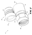
- FIG. 2 is a perspective view of the cable connector of the present invention disassembled and in a shipping configuration.
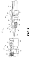
- FIG. 3 is a partial cut-away view of the cable connector of the present invention with a compression sleeve and cable being inserted into an attachment member of the cable connector.
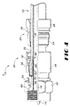
- FIG. 4 is a partial cut-away view of the cable connector of the present invention with a post and barb of the attachment member being inserted under a jacket of the cable.
- FIG. 5 is a partial cut-away view of the cable connector of the present invention with the compression sleeve and cable inserted into the attachment member, and the compression sleeve having a lip disposed therein.
- a coaxial connector 10 is perspectively shown in FIG. 1 for electrically and mechanically connecting a cable 12 to a device such as an electronic component for transmitting or receiving a signal.
- the plurality of layers 68 includes a center conductor 14 for carrying the signal, a dielectric insulator 16, such as foam polyethylene, which encases the center conductor 14, a layer of foil 70 surrounds the insulator 16, at least one braided shield 18 surrounding the foil 70, and a jacket 20, which encases the braided shield 18.
- the jacket 20 may be constructed of a hard polymer such as polyethylene or polyvinyl chloride or an elastomer making radial expansion of the jacket 20 during installation of the cable 12 in the coaxial connector 10 difficult.
- the coaxial connector 10 includes a first main component, which is a compression sleeve 22, as shown in FIGS. 1-5, that is preferably constructed from a synthetic resinous plastic.
- a compression sleeve 22 is preferably constructed from a synthetic resinous plastic.
- acetyl resins are used for this construction such as a linear polyoxymethylene-type acetyl resin marketed under the trademark DELRIN and manufactured by E.I. Du Pont de Nemours and Company of the United States.
- the compression sleeve 22 also includes an annular insertion end 24 and an annular abutment end 28 that is integrally formed with the insertion end 24, and that together form a bore 34 as shown in FIG. 2.
- the compression sleeve 22 further includes an O-ring 26, preferably formed from synthetic rubbers or elastomers, secured between the abutment end 28 and insertion end 24 to seal off environmental elements from entering the connector 10 between the sleeve 22 and the second main component.
- O-ring 26 preferably formed from synthetic rubbers or elastomers
- the second main component of the coaxial connector 10 is an attachment member 40, as shown in FIGS. 1-5, which is preferably fabricated from metal such as brass and plated with another metal such as Cadmium but could also be fabricated a rigid material such as plastic. Moreover, the attachment member 40 may have a coating such as Chromate overlying the Cadmium plating.
- the attachment member 40 includes a nut 42 that has a partially threaded channel 58 extending through it for screwingly engaging the electronic component.
- An O-ring 54 is installed within the channel 58 of the nut 42 to seal off environmental elements from entering the nut 42.
- the O-ring 54 is preferably formed from synthetic rubbers or elastomers.
- the attachment member 40 further includes a post 46 that has a first end 60 disposed in the partially threaded channel 58 of the nut 42 and preferably adjacent the internal threading of the nut 42, and a second free end 62. Integrally formed on the second free end 62 is a small flange or barb 48, as shown in FIGS. 3, 4, and 5.
- the nut 42 is free to rotate about the first end 60 of the post 46.
- the second free end 62 can also be without the barb 48 to further decrease insertion force of the cable 12 into the attachment member 40. Even without the barb 48, the second free end 62 of the post 46 is tapered for easier insertion between the foil 70 and braided shield 18. The functional aspects of the barb 48 will be discussed below when referring to the nut 42 of the coaxial connector 10.
- a collar 44 is coupled to the nut 42 and extends axially therefrom, and in which the post 46 is secured.
- the collar 44 is also preferably constructed of metal, such as brass but could also be constructed of hard plastic, and further defines the channel 58 and includes an internally formed shape 56 of generally decreasing diameter, as shown in FIGS. 3-5. The functional aspects of the shape 56 of generally decreasing diameter will also be discussed in greater detail below.
- the coaxial connector 10 of the present invention is preferably shipped in two joined components; the first being the compression sleeve 22 and the second being the attachment member 40.
- a shipping ring 30, which is integrally formed with sleeve 22 and both are preferably formed of DELRIN but could also be formed of a hard plastic, encircles the attachment member 40 and remains thereon or alternatively is cut off before assembly of the coaxial connector 10.
- the shipping ring 30 is integrally formed with an extension 32 that in turn is integrally formed with the abutment end 28 of the compression sleeve 22, coupling the attachment member 40 to the compression sleeve 22.
- the compression sleeve 22 defines bore 34 for slidably receiving, and through which, the cable 12 is inserted prior to the coaxial connector 10 being assembled.
- the free end of the cable 12 is prepared for installation by a quarter-quarter preparation tool that has two blades of different lengths. A first blade scores the cable 12 to the depth of the center conductor 14 thereby cutting the jacket 20, braided shield 18, foil 70, and the dielectric insulation 16 to the appropriate length. A second blade simultaneously scores the jacket 20 to a shorter length. Then, the remaining underneath length of braided shield 18 is folded over top of the jacket 20 as shown in FIG. 3. The underlying foil 70 is then exposed.
- extra layers 68 of braided shields may be employed together as inner and outer braided shields with a layer of foil in between with the foil being scored and removed, and the inner braided shield being folded over the outer braided shield.
- the cable 12 is then inserted into the bore 34 of the attachment member 40 so that the post 46 or barb 48 is resting on the exposed foil 70.
- the cable 12 is inserted into the attachment member 40 causing the post 46 or barb 48, depending on the embodiment, to be inserted between the foil 70 and the braided shield 18 thereby creating radial expansion of the cable 12 by radial expansion of the jacket 20. It is expressly understood, however, that the post 46 or barb 48 could be inserted between any of the plurality of layers 68 surrounding the dielectric insulation 16 to create radial expansion of the cable 12.
- the collar 44 of the attachment member 40 receives, at least partially, the compression sleeve 22 therein and contacts the abutment end 28.
- the insertion end 24 of the compression sleeve 22 is received inside the portion of the channel 58 that is contained within the collar 44.
- the internal shape 56 of generally decreasing diameter of the collar 44 radially and gradually constricts the compression sleeve 22, and particularly the insertion end 24, when received by the attachment member 40 such that a uniform, radial compression is created around the cable 12.
- axial retention of the cable 12 is thereby created in the coaxial connector 10 such that the connector 10 is sealed from environmental elements entering therein.
- the cable 12 is now fixedly secured within the coaxial connector 10 for later operation and coupling with the electronic device.
- a lip 50 is included on the interior of the insertion end 24 such that the lip 50 prevents the braided shield 18, or any strands thereof, from sliding between the compression sleeve 22 and jacket 20 during installation of the connector 10. This prevention is accomplished by the lip 50 being dimensioned so that it can flex outward to clear the braided shield 18 when the cable is being inserted into the sleeve 22.
- the lip 50 does not flex outward and instead eliminates the clearance space between the sleeve 22 and jacket 20 thereby preventing the braided shield 18 from getting wedged between the sleeve 22 and jacket 20 such that the folded-back portion of the braided shield 18 becomes bunched or curled up.
Landscapes
- Coupling Device And Connection With Printed Circuit (AREA)
Applications Claiming Priority (2)
| Application Number | Priority Date | Filing Date | Title |
|---|---|---|---|
| US17971798A | 1998-10-27 | 1998-10-27 | |
| US179717 | 1998-10-27 |
Publications (1)
| Publication Number | Publication Date |
|---|---|
| EP0997988A2 true EP0997988A2 (de) | 2000-05-03 |
Family
ID=22657688
Family Applications (1)
| Application Number | Title | Priority Date | Filing Date |
|---|---|---|---|
| EP19990308431 Withdrawn EP0997988A2 (de) | 1998-10-27 | 1999-10-26 | Koaxialverbinder |
Country Status (2)
| Country | Link |
|---|---|
| EP (1) | EP0997988A2 (de) |
| CA (1) | CA2282803A1 (de) |
Cited By (4)
| Publication number | Priority date | Publication date | Assignee | Title |
|---|---|---|---|---|
| WO2008005254A2 (en) | 2006-06-29 | 2008-01-10 | Corning Gilbert Inc. | Coaxial connector and method |
| US7445501B1 (en) | 2007-06-08 | 2008-11-04 | John Mezzalingua Assoc., Inc. | Insulator for a coaxial cable connector and method of use thereof |
| CN102255149A (zh) * | 2011-05-13 | 2011-11-23 | 广州国联通信有限公司 | 一种压接式同轴电缆连接器及其连接方法 |
| CN104682081A (zh) * | 2013-11-30 | 2015-06-03 | 中国科学院沈阳自动化研究所 | 一种水密同轴连接器 |
-
1999
- 1999-09-17 CA CA 2282803 patent/CA2282803A1/en not_active Abandoned
- 1999-10-26 EP EP19990308431 patent/EP0997988A2/de not_active Withdrawn
Cited By (5)
| Publication number | Priority date | Publication date | Assignee | Title |
|---|---|---|---|---|
| WO2008005254A2 (en) | 2006-06-29 | 2008-01-10 | Corning Gilbert Inc. | Coaxial connector and method |
| EP2041843A4 (de) * | 2006-06-29 | 2011-03-23 | Corning Gilbert Inc | Koaxialstecker und verfahren |
| US7445501B1 (en) | 2007-06-08 | 2008-11-04 | John Mezzalingua Assoc., Inc. | Insulator for a coaxial cable connector and method of use thereof |
| CN102255149A (zh) * | 2011-05-13 | 2011-11-23 | 广州国联通信有限公司 | 一种压接式同轴电缆连接器及其连接方法 |
| CN104682081A (zh) * | 2013-11-30 | 2015-06-03 | 中国科学院沈阳自动化研究所 | 一种水密同轴连接器 |
Also Published As
| Publication number | Publication date |
|---|---|
| CA2282803A1 (en) | 2000-04-27 |
Similar Documents
| Publication | Publication Date | Title |
|---|---|---|
| EP0871254B1 (de) | Rotierende Erdungskupplung zum äusseren Erden von Gehäusen | |
| US6331123B1 (en) | Connector for hard-line coaxial cable | |
| EP1777783B1 (de) | Koaxialer Verbinder ohne Kabelvorbereitung | |
| US6817896B2 (en) | Cable connector with universal locking sleeve | |
| US7794275B2 (en) | Coaxial cable connector with inner sleeve ring | |
| CA2628726C (en) | Coaxial cable connector with gripping ferrule | |
| US7048578B2 (en) | Tooless coaxial connector | |
| US6780052B2 (en) | Compression connector for coaxial cable and method of installation | |
| US4173385A (en) | Watertight cable connector | |
| US7077700B2 (en) | Coaxial connector with back nut clamping ring | |
| US5186655A (en) | RF connector | |
| US6817897B2 (en) | End connector for coaxial cable | |
| EP3382809B1 (de) | Schnellmontageverbinder für ein koaxialkabel | |
| US20070087628A1 (en) | Coaxial cable connector with self-gripping and self-sealing features | |
| JPH02132781A (ja) | 電気プラグコネクタ用の金属ケーシングスリーブ | |
| US3384703A (en) | Coaxial connector | |
| US10374368B2 (en) | Connector for a coaxial cable | |
| EP0997988A2 (de) | Koaxialverbinder | |
| US10644417B2 (en) | Rotate-to-close connector for a coaxial cable | |
| US20230291156A1 (en) | Enhanced connector post for maintaining a ground path | |
| JP3893041B2 (ja) | 迅速接続コネクタ | |
| WO2019103849A1 (en) | Connector for a coaxial cable | |
| HK1100792B (en) | Prepless coaxial cable connector |
Legal Events
| Date | Code | Title | Description |
|---|---|---|---|
| PUAI | Public reference made under article 153(3) epc to a published international application that has entered the european phase |
Free format text: ORIGINAL CODE: 0009012 |
|
| AK | Designated contracting states |
Kind code of ref document: A2 Designated state(s): AT BE CH CY DE DK ES FI FR GB GR IE IT LI LU MC NL PT SE |
|
| AX | Request for extension of the european patent |
Free format text: AL;LT;LV;MK;RO;SI |
|
| STAA | Information on the status of an ep patent application or granted ep patent |
Free format text: STATUS: THE APPLICATION HAS BEEN WITHDRAWN |
|
| 18W | Application withdrawn |
Withdrawal date: 20000714 |