EP0998043A2 - Method and apparatus for defining and generating local oscillator signals for down converter - Google Patents
Method and apparatus for defining and generating local oscillator signals for down converter Download PDFInfo
- Publication number
- EP0998043A2 EP0998043A2 EP99308641A EP99308641A EP0998043A2 EP 0998043 A2 EP0998043 A2 EP 0998043A2 EP 99308641 A EP99308641 A EP 99308641A EP 99308641 A EP99308641 A EP 99308641A EP 0998043 A2 EP0998043 A2 EP 0998043A2
- Authority
- EP
- European Patent Office
- Prior art keywords
- segments
- waveforms
- digital
- counts
- waveform
- Prior art date
- Legal status (The legal status is an assumption and is not a legal conclusion. Google has not performed a legal analysis and makes no representation as to the accuracy of the status listed.)
- Granted
Links
Images

Classifications
-
- H—ELECTRICITY
- H03—ELECTRONIC CIRCUITRY
- H03K—PULSE TECHNIQUE
- H03K23/00—Pulse counters comprising counting chains; Frequency dividers comprising counting chains
- H03K23/64—Pulse counters comprising counting chains; Frequency dividers comprising counting chains with a base or radix other than a power of two
- H03K23/66—Pulse counters comprising counting chains; Frequency dividers comprising counting chains with a base or radix other than a power of two with a variable counting base, e.g. by presetting or by adding or suppressing pulses
- H03K23/667—Pulse counters comprising counting chains; Frequency dividers comprising counting chains with a base or radix other than a power of two with a variable counting base, e.g. by presetting or by adding or suppressing pulses by switching the base during a counting cycle
Definitions
- the invention relates to the field of defining and generating digital waveforms such as used as the local oscillator input of a down converter where the signals are based on a reference signal, more particularly where the digital waveforms are not an integer submultiple of the frequency of the reference signal.
- the digital waveform or local oscillator signal is some integer, submultiple of the reference signal permitting a divider, or the like, to be used to directly convert the reference signal to the frequency of the local oscillator.
- a divider or the like
- the present invention resulted from an application where a 10MHz reference signal is divided to provide a local oscillator frequency of approximately 131kHz (more precisely 10MHz ⁇ 76) for a down converter. It was found necessary to add a second channel which would receive at approximately 115kHz (more precisely 10MHz ⁇ 86 7/6), while retaining the 10MHz crystal oscillator of the prior system.
- the second local oscillator signal needed for the 115kHz channel is not an integer submultiple of the 10MHz reference frequency.
- prior art provides numerous solutions to this problem including, perhaps the most costly, adding a second crystal oscillator.
- Other prior art solutions include the use of a phase lock loop or the generation of a digital waveform based on two submultiples of the reference signal (e.g., 86 and 87).
- the digital waveform is generated using, for instance, 87 counts of the 10MHz clock for some predetermined number of cycles followed by a cycle of 86 counts to make up for the fact that the frequency of the desired digital waveform is larger than 10MHz/87.
- a method for providing a periodic digital waveform of a predetermined frequency based on a higher frequency reference signal is disclosed.
- the digital waveform has a plurality of segments which are periodically repeated, each segment having a predetermined relationship to the higher frequency signal.
- a plurality of digital waveforms are first generated, each of which has its segments in a different order. Each of these digital waveforms still have the same predetermined frequency even though the order of the segments is different.
- Each of these digital waveforms is examined against some selected criteria such as in the case of the oscillator in a down converter, the performance of the receiver. From the examination of the plurality of digital waveforms, a particular digital waveform is selected and used again by way of example, as the local oscillator signal in the down converter.
- a method for providing a digital waveform which is made up of a plurality of almost periodic segments is described.
- numerous specific details are set forth such as specific frequencies, in order to provide a thorough understanding of the present invention. It will be apparent to one skilled in the art that the present invention may be practiced without these specific details. In other instances, well-known methods and structures, such as counters, have not been described in detail in order not to obscure the present invention.
- the receiver may be part of a power line transceiver which receives communication signals over a power line.
- Such transceivers are manufactured by Echelon Corporation of Palo Alto, California.
- the power line signal after some filtering, is sampled and the digital samples are applied to line 10 of the down converter of Figure 1.
- this input signal is multiplied by local oscillator signals from the oscillator 12.
- An oscillator signal and this signal shifted by approximately 90° are used in the multipliers.
- the signals may be, for instance, square wave or sine wave signals.
- the output of the multipliers is referred to commonly as the "I" and "Q" channels.
- the signals in the I and Q channels receive some digital signal processing such as low pass filtering, shown by digital processing 15 in Figure 1.
- Other well-known circuits may be used to detect the information signal as shown by signal detection circuit 16.
- a transceiver employing the circuit of Figure 1 uses a 10MHz crystal oscillator as a reference signal.
- the down converter for a 131kHz channel uses this 10 MHz reference signal (dividing by 76) to provide the local oscillator signals (dividing 19 to produce quadrature signals) for the multipliers.
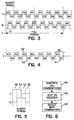
- one cycle of the 0° phase local oscillator waveform comprises a first segment having two 19 counts (total of 38 counts) and a second segment having two 19 counts.
- the 90° phase waveform begins with a 19 count segment to provide the 90° shift. Then there is a segment having two 19 counts followed by another segment with a count of 19 to complete the cycle.
- the present invention arose in an effort to add a second channel to a transceiver which operates at approximately 115kHz (more precisely, 10MHz ⁇ 86 6/7). This frequency has a non-integer relationship to the 10MHz clock (86 6/7).
- the waveform of Figure 4 (as well as other waveforms with segments rearranged) produces some spurious modulation frequencies in the I and Q channels because the waveform is not truly periodic for every cycle. If these modulation frequencies are far enough removed from the base band frequencies of the converter, degradation of the receiver can be avoided. Numerous factors, however, can affect spurious frequencies introduction beyond the shortened cycles or lengthened cycles of the local oscillator. For instance, if the local oscillator provides a square wave output, this signal contains odd multiples of the oscillator fundamental frequency. All these factors can result in an output waveform of the receiver having undesirable characteristic.
- One such undesirable characteristic is the existence of frequency components at the output which have the same value as the information, but are caused when the input waveform has no frequency components near the local oscillator fundamental frequency. These result in what is sometimes called spurious input frequency noise. If this noise is relatively large compared to the size of the desired output waveform when information is present, the receiver performance will be degraded.
- I and Q signals are checked in response to spurious input frequency noise.
- the I and Q signals should have the same amplitude but shifted by 90°. To the extent that this does not occur, there is a degradation in receiver performance.
- Another test is to determine how tolerant a given waveform is to introduction of noise, assuming some fixed error rate.
- a combination may be selected that provides the needed result.
- selecting a combination may not be made on a single criterion such as performance in a given channel. For instance, a combination that provides good performance in the channel it is used in, may result in crosstalk from another channel. Thus, several criteria may be weighed in selecting a combination.
- a particular duty cycle (such as 50%) may limit the number of combinations to only those cycles made up of two segments with approximately the same count.
- Balanced high and low states may be another consideration that limits the number of combinations. This is true for the waveforms of Figure 3. Note that over the full period of seven cycles there are as many counts for high signal levels as for low signal levels. Another consideration may be to keep the I and Q waveforms close to 90° apart.
- This selected sequence for the I channel specifically 43, 44 ,43, 43, 44, 43, 44, 43, 44, 43, 44, 43, 43, 44, 43, 43, 44, 43, 44, 43, 44, 43, 44 and the selected sequence for the Q channel (specifically, 44, 43, 44, 43, 44, 43, 43, 44, 43, 44, 43, 44, 43, 44, 43, 43 following the 21 "phase shift” counts) was selected after testing the receiver with many or all of the combinations.
- the apparatus for generating the waveforms of Figure 3 is shown in Figure 2 and includes a seven state down counter 20.
- the counter 20 starts counting down from six and wraps around at zero back to a count of six.
- the I and Q channel waveforms are as shown in Figure 5.
- Each of the "half" segments represented, for instance, by 50 is either 21 or 22 counts.
- the 21 and 22 counting is provided by the counter 25.
- the waveform look-up table 24 stores the information for each of the channels needed to make up the segments for the waveform of Figure 3. That is, the table stores the time relationship for each segment to the reference signal.
- the table indicates for the I channel that there is a 21 count needed for the half segment 50, followed by a 22 count for the half segment 51.
- a count of 21 is needed followed by two counts of 22 for the half segments 51 and 52.
- the counter 26 advances at the terminal count of counter 25 and generates the waveform of Figure 5 needed to complete the final waveform.
- the down counter 20 is decremented. The counting is synchronized with the reference signal of 10MHz.
Landscapes
- Manipulation Of Pulses (AREA)
- Testing, Inspecting, Measuring Of Stereoscopic Televisions And Televisions (AREA)
- Superheterodyne Receivers (AREA)
- Mobile Radio Communication Systems (AREA)
Abstract
Description
| I = | 43, 44, 44, 43, 44, 43, 43, 43, 44, 44, 43, 44, 43, 43 |
| Q = | (21) 44, 43, 43, 43, 44, 44, 43, 44, 43, 43, 43, 44, 44, 43 |
| I = | 44, 44, 43, 43, 44, 43, 43, 44, 44, 43, 43, 44, 43, 43 |
| Q = | (22) 44, 43, 43, 44, 44, 43, 43, 44, 43, 43, 44, 44, 43, 43 |
| I = | 44, 44, 43, 43, 43, 44, 43, 44, 44, 43, 43, 43, 44, 43 |
| Q = | (22) 43, 44, 43, 44, 44, 43, 43, 43, 44, 43, 44, 44, 43, 43 |
Claims (16)
- A method for providing a periodic digital waveform based on a higher frequency signal, the digital waveform having a plurality of segments which are periodically repeated, each segment having a predetermined relationship to the higher frequency signal, comprising:generating a plurality of the digital waveforms each of which has the segments in a different order;examining each of the plurality of digital waveforms against a selected criterion, andselecting one of the plurality of the digital waveforms based at least in part on the examination of the plurality of digital waveforms.
- The method defined by claim 1 wherein the plurality of digital waveforms includes every combination of the segments.
- The method defined by claim 1 wherein the plurality of digital waveforms is pseudo-randomly generated.
- A method for providing a digital waveform which is derived from a higher frequency signal and wherein the digital waveform is made up of first segments having n counts of the higher frequency signal and of second segments having m counts of the higher frequency signal, the digital waveform periodically having a first predetermined number of first segments and a second predetermined number of second segments, comprising:generating a plurality of the digital waveforms each of which has the first and second number of the first and second segments, respectively, with the first and second segments being differently arranged in each of the plurality of the digital waveforms;testing each of the plurality of the digital waveforms in at least one predetermined test;selecting one of the plurality of digital waveforms based at least in part on the testing.
- The method defined by claim 4 wherein the plurality of digital waveforms comprises every combination of the first and second segments having the first predetermined number and second predetermined number of segments, respectively.
- The method defined by claim 4 wherein the generation of the digital waveform is done by a pseudo-random process.
- The method defined by claims 4 wherein the plurality of digital waveforms have a 50% duty signal over a complete cycle of the waveform.
- The method defined by claims 4 wherein the plurality of digital waveforms have the same number of counts in a high state and a low state over a complete cycle of the waveform.
- The method defined by claim 4 wherein the testing comprises using the plurality of digital waveforms as local oscillator signals in a receiver.
- A method for defining a first and second quadrature, local oscillator signals based on a higher frequency reference signal each of the first signals being made up of first segments and second segments having a fixed relationship to the higher frequency signal and the second signal being made up of second and third segments having a fixed relationship to the higher frequency signal, comprising:generating a plurality of the first signals having the first and second segments in different orders;generating a plurality of the second signals each having the third and fourth segments in different order and each being in quadrature relationship to the plurality of a first signals;testing the first and second signals so as to evaluate their performance as local oscillator signals in a receiver; and,selecting one of the first and second signals for use in the receiver.
- An apparatus for generating a digital waveform having a plurality of segments which are repeated where each segment is based on a fixed time relationship to a reference signal, comprising:a first counter for generating signals for controlling the repeating of segments;a table for storing data representative of the fixed time relationships between the reference signal and each of the segments coupled to the first counter;a second counter for counting intervals corresponding to the time relationship of the reference signal and the segments coupled to the table; anda circuit for providing the digital waveform, coupled to the second counter.
- A down converter for a power line receiver comprising:a reference signal generator;a local oscillator operating under control of the reference signal generator for providing a first and a second waveform of substantially the same frequency but shifted by 90° from one another, the first and second signal being made of segments each having some integer number of counts based on the reference signal, the counts in the segments of the waveforms being irregularly distributed over a full cycle of the waveforms; and,a first and a second multiplexer coupled to receive the first and second waveforms, respectively, and coupled to receive an input signal.
- The converter defined by claim 12 wherein the counts of a 10MHz reference signal for the first waveforms are
43, 44, 43, 43, 44, 43, 44, 43, 44, 43, 43, 44, 43, 44
and the second waveforms are
(21) 44, 43, 44, 43, 44, 43, 43, 44, 43, 44, 43, 44, 43, 44. - The converter defined by claim 12 wherein the counts of a 10MHz reference signal for the first waveforms are
43, 44, 44, 43, 44, 43, 43, 43, 44, 44, 43, 44, 43, 43
and the second waveforms are
(21) 44, 43, 43, 43, 44, 44, 43, 44, 43, 43, 43, 44, 44, 43. - The converter defined by claim 12 wherein the counts of a 10MHz reference signal for the first waveforms are
44, 44, 43, 43, 44, 43, 43, 44, 44, 43, 43, 44, 43, 43
and for the second waveforms are
(22) 44, 43, 43, 44, 44, 43, 43, 44, 43, 43, 44, 44, 43, 43. - The converter defined by claim 12 wherein the counts of a 10MHz reference signal for the first waveforms are
44, 44, 43, 43, 43, 44, 43, 44, 44, 43, 43, 43, 44, 43
and for the second waveforms are
(22) 43, 44, 43, 44, 44, 43, 43, 43, 44, 43, 44, 44, 43, 43.
Applications Claiming Priority (2)
| Application Number | Priority Date | Filing Date | Title |
|---|---|---|---|
| US09/183,588 US6442381B1 (en) | 1998-10-30 | 1998-10-30 | Method and apparatus for defining and generating local oscillator signals for down converter |
| US183588 | 1998-10-30 |
Publications (3)
| Publication Number | Publication Date |
|---|---|
| EP0998043A2 true EP0998043A2 (en) | 2000-05-03 |
| EP0998043A3 EP0998043A3 (en) | 2001-01-17 |
| EP0998043B1 EP0998043B1 (en) | 2009-09-02 |
Family
ID=22673458
Family Applications (1)
| Application Number | Title | Priority Date | Filing Date |
|---|---|---|---|
| EP99308641A Expired - Lifetime EP0998043B1 (en) | 1998-10-30 | 1999-11-01 | Method and apparatus for defining and generating local oscillator signals for down converter |
Country Status (2)
| Country | Link |
|---|---|
| US (2) | US6442381B1 (en) |
| EP (1) | EP0998043B1 (en) |
Families Citing this family (4)
| Publication number | Priority date | Publication date | Assignee | Title |
|---|---|---|---|---|
| FR2808633B1 (en) * | 2000-05-04 | 2002-07-26 | Sagem | MULTIBAND SHORT RADIO RECEIVER FOR MOTOR VEHICLE DATA |
| US6711397B1 (en) * | 2000-11-20 | 2004-03-23 | Ami Semiconductor, Inc. | Structures and methods for direct conversion from radio frequency modulated signals to baseband signals |
| US20040002320A1 (en) * | 2002-06-28 | 2004-01-01 | Ching-Lang Lin | Square wave local oscillator technique for direct conversion receiver |
| US20080297309A1 (en) * | 2007-05-29 | 2008-12-04 | Marc Loyer | Waveform synthesis in rfid interrogators |
Family Cites Families (12)
| Publication number | Priority date | Publication date | Assignee | Title |
|---|---|---|---|---|
| DE2854427A1 (en) | 1978-12-16 | 1980-06-26 | Bayer Ag | METHOD AND APPARATUS FOR THE RECOVERY OF DRY 1,5- AND / OR 1,8- DINITROANTHRAQUINONE FROM SUSPENSIONS CONTAINING SOLID 1,5- AND / OR 1,8-DINITROANTHRAQUINONE AND LIQUID NITROBENZENE |
| GB2049245A (en) | 1979-05-09 | 1980-12-17 | Marconi Co Ltd | Frequency synthesisers |
| GB2140232B (en) | 1983-05-17 | 1986-10-29 | Marconi Instruments Ltd | Frequency synthesisers |
| DE3521288A1 (en) | 1985-06-13 | 1986-12-18 | Siemens AG, 1000 Berlin und 8000 München | Arrangement for digital division of an input cycle |
| GB2252879B (en) | 1988-04-15 | 1992-12-16 | Racal Res Ltd | Frequency synthesizers |
| DE3826006C1 (en) | 1988-07-30 | 1989-10-12 | Wandel & Goltermann Gmbh & Co, 7412 Eningen, De | |
| US5097487A (en) * | 1989-10-24 | 1992-03-17 | Walp Patrick K | Local oscillator signal generating system for digital demodulator |
| JPH06504888A (en) | 1990-06-05 | 1994-06-02 | コーヒーレント・アイピイ・ライツ・リミテッド | Method and device for transmitting data over power lines |
| US5267189A (en) | 1991-09-30 | 1993-11-30 | Wilke William G | Rational fraction synthesizer |
| US5495206A (en) | 1993-10-29 | 1996-02-27 | Motorola, Inc. | Fractional N frequency synthesis with residual error correction and method thereof |
| JP2738385B2 (en) * | 1996-04-15 | 1998-04-08 | 日本電気株式会社 | Variable bandwidth frequency division multiplex communication system |
| US6018553A (en) * | 1996-09-18 | 2000-01-25 | Wireless Access | Multi-level mixer architecture for direct conversion of FSK signals |
-
1998
- 1998-10-30 US US09/183,588 patent/US6442381B1/en not_active Expired - Lifetime
-
1999
- 1999-11-01 EP EP99308641A patent/EP0998043B1/en not_active Expired - Lifetime
-
2001
- 2001-01-25 US US09/770,409 patent/US6484018B1/en not_active Expired - Lifetime
Also Published As
| Publication number | Publication date |
|---|---|
| US6442381B1 (en) | 2002-08-27 |
| US6484018B1 (en) | 2002-11-19 |
| EP0998043B1 (en) | 2009-09-02 |
| EP0998043A3 (en) | 2001-01-17 |
Similar Documents
| Publication | Publication Date | Title |
|---|---|---|
| TW480825B (en) | Low jitter phase-locked loop with duty-cycle control | |
| US5867068A (en) | Frequency synthesizer using double resolution fractional frequency division | |
| Roza | Analysis of phase-locked timing extraction circuits for pulse code transmission | |
| US20060056490A1 (en) | Spread spectrum clock generator and method of generating spread spectrum clock | |
| JPS61296843A (en) | Signal/noise ratio exponent generation apparatus and method for coding digital data | |
| CN112290934A (en) | Controllable jitter clock generation device based on Bias-Tee signal synthesis | |
| US6442381B1 (en) | Method and apparatus for defining and generating local oscillator signals for down converter | |
| CN212460415U (en) | Digital test circuit and digital integrated circuit test system of multi-clock domain | |
| US7664166B2 (en) | Pleisiochronous repeater system and components thereof | |
| US7079612B2 (en) | Fast bit-error-rate (BER) test | |
| JP3072509B2 (en) | Timing control circuit of PAM communication device | |
| KR20040024468A (en) | Random number generator | |
| CN115580361A (en) | Test calibration equipment DRFM (digital radio frequency modulation) of electronic countermeasure equipment and working method thereof | |
| US6956922B2 (en) | Generating non-integer clock division | |
| D’Arco et al. | A time base option for arbitrary selection of sample rate in digital storage oscilloscopes | |
| CN103296972A (en) | Downconversion of comb spectrum | |
| US6317457B1 (en) | Pulse density modulator | |
| US5056108A (en) | Communication system | |
| US5058142A (en) | Clock extracting circuit in digital-line signal receiver | |
| Chakrabarti et al. | Design of sequences with specified autocorrelation and cross correlation | |
| JP4121951B2 (en) | Random generator | |
| US6563867B2 (en) | Arrangement for analyzing the nonlinear properties of a communication channel | |
| CN120281315B (en) | Broadband arbitrary reference self-adaptive clock synchronizer | |
| US5017801A (en) | Method and apparatus for converting a gap-infested read-in clock into a gap-free read-out clock | |
| Darby et al. | Programmable frequency-hop synthesizers based on chirp mixing |
Legal Events
| Date | Code | Title | Description |
|---|---|---|---|
| PUAI | Public reference made under article 153(3) epc to a published international application that has entered the european phase |
Free format text: ORIGINAL CODE: 0009012 |
|
| AK | Designated contracting states |
Kind code of ref document: A2 Designated state(s): FR GB IT |
|
| AX | Request for extension of the european patent |
Free format text: AL;LT;LV;MK;RO;SI |
|
| PUAL | Search report despatched |
Free format text: ORIGINAL CODE: 0009013 |
|
| AK | Designated contracting states |
Kind code of ref document: A3 Designated state(s): AT BE CH CY DE DK ES FI FR GB GR IE IT LI LU MC NL PT SE |
|
| AX | Request for extension of the european patent |
Free format text: AL;LT;LV;MK;RO;SI |
|
| RIC1 | Information provided on ipc code assigned before grant |
Free format text: 7H 03K 23/68 A, 7H 03K 23/66 B, 7H 03L 7/197 B |
|
| 17P | Request for examination filed |
Effective date: 20010707 |
|
| AKX | Designation fees paid |
Free format text: FR GB IT |
|
| REG | Reference to a national code |
Ref country code: DE Ref legal event code: 8566 |
|
| 17Q | First examination report despatched |
Effective date: 20070822 |
|
| GRAP | Despatch of communication of intention to grant a patent |
Free format text: ORIGINAL CODE: EPIDOSNIGR1 |
|
| GRAS | Grant fee paid |
Free format text: ORIGINAL CODE: EPIDOSNIGR3 |
|
| GRAA | (expected) grant |
Free format text: ORIGINAL CODE: 0009210 |
|
| AK | Designated contracting states |
Kind code of ref document: B1 Designated state(s): FR GB IT |
|
| PLBE | No opposition filed within time limit |
Free format text: ORIGINAL CODE: 0009261 |
|
| STAA | Information on the status of an ep patent application or granted ep patent |
Free format text: STATUS: NO OPPOSITION FILED WITHIN TIME LIMIT |
|
| 26N | No opposition filed |
Effective date: 20100603 |
|
| PG25 | Lapsed in a contracting state [announced via postgrant information from national office to epo] |
Ref country code: IT Free format text: LAPSE BECAUSE OF FAILURE TO SUBMIT A TRANSLATION OF THE DESCRIPTION OR TO PAY THE FEE WITHIN THE PRESCRIBED TIME-LIMIT Effective date: 20090902 |
|
| REG | Reference to a national code |
Ref country code: FR Ref legal event code: PLFP Year of fee payment: 17 |
|
| REG | Reference to a national code |
Ref country code: FR Ref legal event code: PLFP Year of fee payment: 18 |
|
| REG | Reference to a national code |
Ref country code: FR Ref legal event code: PLFP Year of fee payment: 19 |
|
| PGFP | Annual fee paid to national office [announced via postgrant information from national office to epo] |
Ref country code: FR Payment date: 20181127 Year of fee payment: 20 Ref country code: GB Payment date: 20181127 Year of fee payment: 20 |
|
| REG | Reference to a national code |
Ref country code: GB Ref legal event code: PE20 Expiry date: 20191031 |
|
| PG25 | Lapsed in a contracting state [announced via postgrant information from national office to epo] |
Ref country code: GB Free format text: LAPSE BECAUSE OF EXPIRATION OF PROTECTION Effective date: 20191031 |