EP0998043B1 - Procédé et dispositif pour définir et générer des signaux d'oscillateur local déstinés à un convertisseur abaisseur - Google Patents
Procédé et dispositif pour définir et générer des signaux d'oscillateur local déstinés à un convertisseur abaisseur Download PDFInfo
- Publication number
- EP0998043B1 EP0998043B1 EP99308641A EP99308641A EP0998043B1 EP 0998043 B1 EP0998043 B1 EP 0998043B1 EP 99308641 A EP99308641 A EP 99308641A EP 99308641 A EP99308641 A EP 99308641A EP 0998043 B1 EP0998043 B1 EP 0998043B1
- Authority
- EP
- European Patent Office
- Prior art keywords
- counts
- signal
- local oscillator
- signals
- segments
- Prior art date
- Legal status (The legal status is an assumption and is not a legal conclusion. Google has not performed a legal analysis and makes no representation as to the accuracy of the status listed.)
- Expired - Lifetime
Links
- 238000000034 method Methods 0.000 title claims description 11
- 238000012360 testing method Methods 0.000 claims description 9
- 230000000737 periodic effect Effects 0.000 description 8
- 239000013078 crystal Substances 0.000 description 4
- 230000015556 catabolic process Effects 0.000 description 3
- 238000006731 degradation reaction Methods 0.000 description 3
- 238000010586 diagram Methods 0.000 description 2
- 238000001914 filtration Methods 0.000 description 2
- 238000012545 processing Methods 0.000 description 2
- 230000001360 synchronised effect Effects 0.000 description 2
- 238000004891 communication Methods 0.000 description 1
- 238000013461 design Methods 0.000 description 1
- 238000001514 detection method Methods 0.000 description 1
- 230000010363 phase shift Effects 0.000 description 1
- 238000004088 simulation Methods 0.000 description 1
Images

Classifications
-
- H—ELECTRICITY
- H03—ELECTRONIC CIRCUITRY
- H03K—PULSE TECHNIQUE
- H03K23/00—Pulse counters comprising counting chains; Frequency dividers comprising counting chains
- H03K23/64—Pulse counters comprising counting chains; Frequency dividers comprising counting chains with a base or radix other than a power of two
- H03K23/66—Pulse counters comprising counting chains; Frequency dividers comprising counting chains with a base or radix other than a power of two with a variable counting base, e.g. by presetting or by adding or suppressing pulses
- H03K23/667—Pulse counters comprising counting chains; Frequency dividers comprising counting chains with a base or radix other than a power of two with a variable counting base, e.g. by presetting or by adding or suppressing pulses by switching the base during a counting cycle
Definitions
- the invention relates to the field of defining and generating digital waveforms such as used as the local oscillator input of a down converter where the signals are based on a reference signal, more particularly where the digital waveforms are not an integer submultiple of the frequency of the reference signal.
- the digital waveform or local oscillator signal is some integer, submultiple of the reference signal permitting a divider, or the like, to be used to directly convert the reference signal to the frequency of the local oscillator.
- a divider or the like
- the present invention resulted from an application where a 10MHz reference signal is divided to provide a local oscillator frequency of approximately 131kHz (more precisely 10MHz ⁇ 76) for a down converter. It was found necessary to add a second channel which would receive at approximately 115kHz (more precisely 10MHz ⁇ 86 7/6), while retaining the 10MHz crystal oscillator of the prior system.
- the second local oscillator signal needed for the 115kHz channel is not an integer submultiple of the 10MHz reference frequency.
- prior art provides numerous solutions to this problem including, perhaps the most costly, adding a second crystal oscillator.
- Other prior art solutions include the use of a phase lock loop or the generation of a digital waveform based on two submultiples of the reference signal (e.g., 86 and 87).
- the digital waveform is generated using, for instance, 87 counts of the 10MHz clock for some predetermined number of cycles followed by a cycle of 86 counts to make up for the fact that the frequency of the desired digital waveform is larger than 10MHz/87.
- a method for providing a digital waveform which is made up of a plurality of almost periodic segments is described.
- numerous specific details are set forth such as specific frequencies, in order to provide a thorough understanding of the present invention. It will be apparent to one skilled in the art that the present invention may be practiced without these specific details. In other instances, well-known methods and structures, such as counters, have not been described in detail in order not to obscure the present invention.
- the receiver may be part of a power line transceiver which receives communication signals over a power line.
- Such transceivers are manufactured by Echelon Corporation of Palo Alto, California.
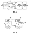
- the power line signal after some filtering, is sampled and the digital samples are applied to line 10 of the down converter of Figure 1 .
- this input signal is multiplied by local oscillator signals from the oscillator 12.
- An oscillator signal and this signal shifted by approximately 90° are used in the multipliers.
- the signals may be, for instance, square wave or sine wave signals.
- the output of the multipliers is referred to commonly as the "I" and "Q" channels.
- the signals in the I and Q channels receive some digital signal processing such as low pass filtering, shown by digital processing 15 in Figure 1 .
- Other well-known circuits may be used to detect the information signal as shown by signal detection circuit 16.
- a transceiver employing the circuit of Figure 1 uses a 10MHz crystal oscillator as a reference signal.
- the down converter for a 131kHz channel uses this 10 MHz reference signal (dividing by 76) to provide the local oscillator signals (dividing 19 to produce quadrature signals) for the multipliers.
- one cycle of the 0° phase local oscillator waveform comprises a first segment having two 19 counts (total of 38 counts) and a second segment having two 19 counts.
- the 90° phase waveform begins with a 19 count segment to provide the 90° shift. Then there is a segment having two 19 counts followed by another segment with a count of 19 to complete the cycle.
- the present invention arose in an effort to add a second channel to a transceiver which operates at approximately 115kHz (more precisely, 10MHz ⁇ 86 6/7). This frequency has a non-integer relationship to the 10MHz clock (86 6/7).
- FIG. 4 One method of obtaining the desired local oscillator frequency for the 115kHz channel is shown in Figure 4 . Segments corresponding to "half" cycles having 43 and 44 counts (such as segments 52 and 53) of the 10MHz clock can be used. As shown 6 "almost periodic" cycles consisting of a 43 count segment and a 44 count segment for each cycle, followed by a last cycle 50 having 43 counts in both segments are used. This provides the exact number of total counts to accurately obtain the frequency needed.
- the waveform of Figure 4 (as well as other waveforms with segments rearranged) produces some spurious modulation frequencies in the I and Q channels because the waveform is not truly periodic for every cycle. If these modulation frequencies are far enough removed from the base band frequencies of the converter, degradation of the receiver can be avoided. Numerous factors, however, can affect spurious frequencies introduction beyond the shortened cycles or lengthened cycles of the local oscillator. For instance, if the local oscillator provides a square wave output, this signal contains odd multiples of the oscillator fundamental frequency. All these factors can result in an output waveform of the receiver having undesirable characteristic.
- One such undesirable characteristic is the existence of frequency components at the output which have the same value as the information, but are caused when the input waveform has no frequency components near the local oscillator fundamental frequency. These result in what is sometimes called spurious input frequency noise. If this noise is relatively large compared to the size of the desired output waveform when information is present, the receiver performance will be degraded.
- I and Q signals are checked in response to spurious input frequency noise.
- the I and Q signals should have the same amplitude but shifted by 90°. To the extent that this does not occur, there is a degradation in receiver performance.
- Another test is to determine how tolerant a given waveform is to introduction of noise, assuming some fixed error rate.
- a combination may be selected that provides the needed result.
- selecting a combination may not be made on a single criterion such as performance in a given channel. For instance, a combination that provides good performance in the channel it is used in, may result in crosstalk from another channel. Thus, several criteria may be weighed in selecting a combination.
- a particular duty cycle (such as 50%) may limit the number of combinations to only those cycles made up of two segments with approximately the same count.
- Balanced high and low states may be another consideration that limits the number of combinations. This is true for the waveforms of Figure 3 . Note that over the full period of seven cycles there are as many counts for high signal levels as for low signal levels. Another consideration may be to keep the I and Q waveforms close to 90° apart.
- This selected sequence for the I channel specifically 43, 44 ,43, 43, 44, 43, 44, 43, 44, 43, 44, 43, 43, 44, 43, 43, 44, 43, 44, 43, 44, 43, 44 and the selected sequence for the Q channel (specifically, 44, 43, 44, 43, 44, 43, 43, 44, 43, 44, 43, 44, 43, 44, 43, 43 following the 21 "phase shift” counts) was selected after testing the receiver with many or all of the combinations.
- the apparatus for generating the waveforms of Figure 3 is shown in Figure 2 and includes a seven state down counter 20.
- the counter 20 starts counting down from six and wraps around at zero back to a count of six.
- the I and Q channel waveforms are as shown in Figure 5 .
- Each of the "half" segments represented, for instance, by 50 is either 21 or 22 counts.
- the 21 and 22 counting is provided by the counter 25.
- the waveform look-up table 24 stores the information for each of the channels needed to make up the segments for the waveform of Figure 3 . That is, the table stores the time relationship for each segment to the reference signal.
- the table indicates for the I channel that there is a 21 count needed for the half segment 50, followed by a 22 count for the half segment 51.
- a count of 21 is needed followed by two counts of 22 for the half segments 51 and 52.
- the counter 26 advances at the terminal count of counter 25 and generates the waveform of Figure 5 needed to complete the final waveform.
- the down counter 20 is decremented. The counting is synchronized with the reference signal of 10MHz.
Landscapes
- Manipulation Of Pulses (AREA)
- Testing, Inspecting, Measuring Of Stereoscopic Televisions And Televisions (AREA)
- Superheterodyne Receivers (AREA)
- Mobile Radio Communication Systems (AREA)
Claims (1)
- Procédé de division numérique d'un signal de référence à fréquence supérieure en un signal d'oscillateur local, ayant
des premiers et des deuxièmes signaux d'oscillateur local en quadrature basés sur le signal de référence à fréquence supérieure, chaque cycle du premier signal étant fait d'un premier segment ayant un nombre de coups prédéterminé en relation fixe avec le signal à fréquence supérieure et d'un deuxième segment ayant un nombre de coups prédéterminé en relation fixe avec le signal à fréquence supérieure, chaque cycle du deuxième signal étant constitué d'un troisième segment ayant un nombre de coups prédéterminé en relation fixe avec le signal à fréquence supérieure et d'un quatrième segment ayant une nombre de coups prédéterminé en relation fixe avec le signal à fréquence supérieure, le procédé comprenant les étapes consistant à :générer (60) une pluralité des premiers signaux ayant le premier et le deuxième segments dans des ordres différents ;générer (60) une pluralité des deuxièmes signaux possédant chacun le troisième et le quatrième segment dans un ordre différent et étant chacun en relation de quadrature avec la pluralité de premiers signaux ;tester (62) les premiers et deuxièmes signaux de manière à évaluer leur performance comme signaux d'oscillateur local dans un récepteur ; etchoisir (63) l'un des premiers et deuxièmes signaux pour une utilisation dans le récepteur.
Applications Claiming Priority (2)
| Application Number | Priority Date | Filing Date | Title |
|---|---|---|---|
| US09/183,588 US6442381B1 (en) | 1998-10-30 | 1998-10-30 | Method and apparatus for defining and generating local oscillator signals for down converter |
| US183588 | 1998-10-30 |
Publications (3)
| Publication Number | Publication Date |
|---|---|
| EP0998043A2 EP0998043A2 (fr) | 2000-05-03 |
| EP0998043A3 EP0998043A3 (fr) | 2001-01-17 |
| EP0998043B1 true EP0998043B1 (fr) | 2009-09-02 |
Family
ID=22673458
Family Applications (1)
| Application Number | Title | Priority Date | Filing Date |
|---|---|---|---|
| EP99308641A Expired - Lifetime EP0998043B1 (fr) | 1998-10-30 | 1999-11-01 | Procédé et dispositif pour définir et générer des signaux d'oscillateur local déstinés à un convertisseur abaisseur |
Country Status (2)
| Country | Link |
|---|---|
| US (2) | US6442381B1 (fr) |
| EP (1) | EP0998043B1 (fr) |
Families Citing this family (4)
| Publication number | Priority date | Publication date | Assignee | Title |
|---|---|---|---|---|
| FR2808633B1 (fr) * | 2000-05-04 | 2002-07-26 | Sagem | Recepteur radio courte portee multibande pour donnees de vehicule automobile |
| US6711397B1 (en) * | 2000-11-20 | 2004-03-23 | Ami Semiconductor, Inc. | Structures and methods for direct conversion from radio frequency modulated signals to baseband signals |
| US20040002320A1 (en) * | 2002-06-28 | 2004-01-01 | Ching-Lang Lin | Square wave local oscillator technique for direct conversion receiver |
| US20080297309A1 (en) * | 2007-05-29 | 2008-12-04 | Marc Loyer | Waveform synthesis in rfid interrogators |
Family Cites Families (12)
| Publication number | Priority date | Publication date | Assignee | Title |
|---|---|---|---|---|
| DE2854427A1 (de) | 1978-12-16 | 1980-06-26 | Bayer Ag | Verfahren und vorrichtung zur gewinnung von trockenem 1,5- und/oder 1,8- dinitroanthrachinon aus suspensionen, die festes 1,5- und/oder 1,8-dinitroanthrachinon und fluessiges nitrobenzol enthalten |
| GB2049245A (en) | 1979-05-09 | 1980-12-17 | Marconi Co Ltd | Frequency synthesisers |
| GB2140232B (en) | 1983-05-17 | 1986-10-29 | Marconi Instruments Ltd | Frequency synthesisers |
| DE3521288A1 (de) | 1985-06-13 | 1986-12-18 | Siemens AG, 1000 Berlin und 8000 München | Anordnug zur digitalen teilung eines eingangstaktes |
| GB2252879B (en) | 1988-04-15 | 1992-12-16 | Racal Res Ltd | Frequency synthesizers |
| DE3826006C1 (fr) | 1988-07-30 | 1989-10-12 | Wandel & Goltermann Gmbh & Co, 7412 Eningen, De | |
| US5097487A (en) * | 1989-10-24 | 1992-03-17 | Walp Patrick K | Local oscillator signal generating system for digital demodulator |
| JPH06504888A (ja) | 1990-06-05 | 1994-06-02 | コーヒーレント・アイピイ・ライツ・リミテッド | 電力線を介してデータを伝送する方法と装置 |
| US5267189A (en) | 1991-09-30 | 1993-11-30 | Wilke William G | Rational fraction synthesizer |
| US5495206A (en) | 1993-10-29 | 1996-02-27 | Motorola, Inc. | Fractional N frequency synthesis with residual error correction and method thereof |
| JP2738385B2 (ja) * | 1996-04-15 | 1998-04-08 | 日本電気株式会社 | 可変帯域幅周波数分割多重通信方式 |
| US6018553A (en) * | 1996-09-18 | 2000-01-25 | Wireless Access | Multi-level mixer architecture for direct conversion of FSK signals |
-
1998
- 1998-10-30 US US09/183,588 patent/US6442381B1/en not_active Expired - Lifetime
-
1999
- 1999-11-01 EP EP99308641A patent/EP0998043B1/fr not_active Expired - Lifetime
-
2001
- 2001-01-25 US US09/770,409 patent/US6484018B1/en not_active Expired - Lifetime
Also Published As
| Publication number | Publication date |
|---|---|
| US6442381B1 (en) | 2002-08-27 |
| US6484018B1 (en) | 2002-11-19 |
| EP0998043A2 (fr) | 2000-05-03 |
| EP0998043A3 (fr) | 2001-01-17 |
Similar Documents
| Publication | Publication Date | Title |
|---|---|---|
| TW480825B (en) | Low jitter phase-locked loop with duty-cycle control | |
| US7508278B2 (en) | Asymmetry triangular frequency modulation profiles for spread spectrum clock generations | |
| US5926514A (en) | Apparatus for clock shifting in an integrated transceiver | |
| JP4903969B2 (ja) | 回転周波数合成器 | |
| JP2806059B2 (ja) | 位相同期ループシンセサイザ | |
| Roza | Analysis of phase-locked timing extraction circuits for pulse code transmission | |
| US5499280A (en) | Clock signal generation | |
| CN112290934A (zh) | 基于Bias-Tee信号合成的可控抖动时钟产生装置 | |
| EP0712211B1 (fr) | Modulation de phase ayant des fronts placés individuellement | |
| WO1999022449A1 (fr) | Synthetiseur de frequence mettant en oeuvre une division de frequence fractionnaire a double resolution | |
| JPS61296843A (ja) | コ−ド化デイジタル・デ−タ用信号対雑音比指数生成装置および方法 | |
| KR100973725B1 (ko) | Dds를 이용한 클럭 발생 장치 | |
| US7664166B2 (en) | Pleisiochronous repeater system and components thereof | |
| US6442381B1 (en) | Method and apparatus for defining and generating local oscillator signals for down converter | |
| CN212460415U (zh) | 多时钟域的数字测试电路、数字集成电路测试系统 | |
| US6999545B2 (en) | Method and system for undersampled symbol synchronization | |
| JP3072509B2 (ja) | Pam方式通信装置のタイミング制御回路 | |
| KR20040024468A (ko) | 난수 발생기 | |
| US6956922B2 (en) | Generating non-integer clock division | |
| US4318045A (en) | Symmetrical waveform signal generator having coherent frequency shift capability | |
| US20050248380A1 (en) | System and method for generating multiple clock signals | |
| US6317457B1 (en) | Pulse density modulator | |
| EP0493607A1 (fr) | Circuit regenerateur de signaux d'horloge | |
| US6711694B1 (en) | Apparatus and method for generating a modulated clock signal including harmonics that exhibit a known sideband configuration | |
| JP2005508581A (ja) | ランダムジュネレータ |
Legal Events
| Date | Code | Title | Description |
|---|---|---|---|
| PUAI | Public reference made under article 153(3) epc to a published international application that has entered the european phase |
Free format text: ORIGINAL CODE: 0009012 |
|
| AK | Designated contracting states |
Kind code of ref document: A2 Designated state(s): FR GB IT |
|
| AX | Request for extension of the european patent |
Free format text: AL;LT;LV;MK;RO;SI |
|
| PUAL | Search report despatched |
Free format text: ORIGINAL CODE: 0009013 |
|
| AK | Designated contracting states |
Kind code of ref document: A3 Designated state(s): AT BE CH CY DE DK ES FI FR GB GR IE IT LI LU MC NL PT SE |
|
| AX | Request for extension of the european patent |
Free format text: AL;LT;LV;MK;RO;SI |
|
| RIC1 | Information provided on ipc code assigned before grant |
Free format text: 7H 03K 23/68 A, 7H 03K 23/66 B, 7H 03L 7/197 B |
|
| 17P | Request for examination filed |
Effective date: 20010707 |
|
| AKX | Designation fees paid |
Free format text: FR GB IT |
|
| REG | Reference to a national code |
Ref country code: DE Ref legal event code: 8566 |
|
| 17Q | First examination report despatched |
Effective date: 20070822 |
|
| GRAP | Despatch of communication of intention to grant a patent |
Free format text: ORIGINAL CODE: EPIDOSNIGR1 |
|
| GRAS | Grant fee paid |
Free format text: ORIGINAL CODE: EPIDOSNIGR3 |
|
| GRAA | (expected) grant |
Free format text: ORIGINAL CODE: 0009210 |
|
| AK | Designated contracting states |
Kind code of ref document: B1 Designated state(s): FR GB IT |
|
| PLBE | No opposition filed within time limit |
Free format text: ORIGINAL CODE: 0009261 |
|
| STAA | Information on the status of an ep patent application or granted ep patent |
Free format text: STATUS: NO OPPOSITION FILED WITHIN TIME LIMIT |
|
| 26N | No opposition filed |
Effective date: 20100603 |
|
| PG25 | Lapsed in a contracting state [announced via postgrant information from national office to epo] |
Ref country code: IT Free format text: LAPSE BECAUSE OF FAILURE TO SUBMIT A TRANSLATION OF THE DESCRIPTION OR TO PAY THE FEE WITHIN THE PRESCRIBED TIME-LIMIT Effective date: 20090902 |
|
| REG | Reference to a national code |
Ref country code: FR Ref legal event code: PLFP Year of fee payment: 17 |
|
| REG | Reference to a national code |
Ref country code: FR Ref legal event code: PLFP Year of fee payment: 18 |
|
| REG | Reference to a national code |
Ref country code: FR Ref legal event code: PLFP Year of fee payment: 19 |
|
| PGFP | Annual fee paid to national office [announced via postgrant information from national office to epo] |
Ref country code: FR Payment date: 20181127 Year of fee payment: 20 Ref country code: GB Payment date: 20181127 Year of fee payment: 20 |
|
| REG | Reference to a national code |
Ref country code: GB Ref legal event code: PE20 Expiry date: 20191031 |
|
| PG25 | Lapsed in a contracting state [announced via postgrant information from national office to epo] |
Ref country code: GB Free format text: LAPSE BECAUSE OF EXPIRATION OF PROTECTION Effective date: 20191031 |