EP0998616B1 - Dispositif de guidage pour le vitrage d'un balcon ou analogue - Google Patents
Dispositif de guidage pour le vitrage d'un balcon ou analogue Download PDFInfo
- Publication number
- EP0998616B1 EP0998616B1 EP98935060A EP98935060A EP0998616B1 EP 0998616 B1 EP0998616 B1 EP 0998616B1 EP 98935060 A EP98935060 A EP 98935060A EP 98935060 A EP98935060 A EP 98935060A EP 0998616 B1 EP0998616 B1 EP 0998616B1
- Authority
- EP
- European Patent Office
- Prior art keywords
- guide arrangement
- fixing
- guide
- opening
- arrangement
- Prior art date
- Legal status (The legal status is an assumption and is not a legal conclusion. Google has not performed a legal analysis and makes no representation as to the accuracy of the status listed.)
- Expired - Lifetime
Links
- 238000000034 method Methods 0.000 claims abstract description 8
- 238000009434 installation Methods 0.000 claims description 18
- XLYOFNOQVPJJNP-UHFFFAOYSA-N water Substances O XLYOFNOQVPJJNP-UHFFFAOYSA-N 0.000 claims description 9
- 239000000463 material Substances 0.000 description 5
- 238000010276 construction Methods 0.000 description 3
- 238000001125 extrusion Methods 0.000 description 2
- 238000004519 manufacturing process Methods 0.000 description 2
- 230000004075 alteration Effects 0.000 description 1
- 238000012986 modification Methods 0.000 description 1
- 230000004048 modification Effects 0.000 description 1
- 238000009418 renovation Methods 0.000 description 1
- 239000007787 solid Substances 0.000 description 1
Images

Classifications
-
- E—FIXED CONSTRUCTIONS
- E05—LOCKS; KEYS; WINDOW OR DOOR FITTINGS; SAFES
- E05D—HINGES OR SUSPENSION DEVICES FOR DOORS, WINDOWS OR WINGS
- E05D15/00—Suspension arrangements for wings
- E05D15/06—Suspension arrangements for wings for wings sliding horizontally more or less in their own plane
- E05D15/0621—Details, e.g. suspension or supporting guides
- E05D15/066—Details, e.g. suspension or supporting guides for wings supported at the bottom
- E05D15/0686—Tracks
-
- E—FIXED CONSTRUCTIONS
- E06—DOORS, WINDOWS, SHUTTERS, OR ROLLER BLINDS IN GENERAL; LADDERS
- E06B—FIXED OR MOVABLE CLOSURES FOR OPENINGS IN BUILDINGS, VEHICLES, FENCES OR LIKE ENCLOSURES IN GENERAL, e.g. DOORS, WINDOWS, BLINDS, GATES
- E06B3/00—Window sashes, door leaves, or like elements for closing wall or like openings; Layout of fixed or moving closures, e.g. windows in wall or like openings; Features of rigidly-mounted outer frames relating to the mounting of wing frames
- E06B3/92—Doors or windows extensible when set in position
- E06B3/922—Doors or windows extensible when set in position with several wings opening horizontally towards the same side of the opening and each closing a separate part of the opening
- E06B3/924—Doors or windows extensible when set in position with several wings opening horizontally towards the same side of the opening and each closing a separate part of the opening positioned in one plane when closed
-
- E—FIXED CONSTRUCTIONS
- E05—LOCKS; KEYS; WINDOW OR DOOR FITTINGS; SAFES
- E05Y—INDEXING SCHEME ASSOCIATED WITH SUBCLASSES E05D AND E05F, RELATING TO CONSTRUCTION ELEMENTS, ELECTRIC CONTROL, POWER SUPPLY, POWER SIGNAL OR TRANSMISSION, USER INTERFACES, MOUNTING OR COUPLING, DETAILS, ACCESSORIES, AUXILIARY OPERATIONS NOT OTHERWISE PROVIDED FOR, APPLICATION THEREOF
- E05Y2900/00—Application of doors, windows, wings or fittings thereof
- E05Y2900/10—Application of doors, windows, wings or fittings thereof for buildings or parts thereof
- E05Y2900/13—Type of wing
- E05Y2900/148—Windows
- E05Y2900/15—Balcony glazing
Definitions
- the invention relates to a guide arrangement for balcony glazing, which is intended to be installed in an opening in a structure and to comprise two or more panes or the like, supported on their horizontal upper and lower edges with the guide arrangement and arranged to be movable in the guide arrangement.
- the panes are arranged to pivot around a vertical pivoting axis to a storage position substantially perpendicular to the longitudinal direction of the guide arrangement, from a longitudinal use position of the guide arrangement, in which the panes or the like are placed one after the other at the location of the opening in the structure.
- the guide arrangement is provided with a groove or the like, in which the guiding and pivoting means of each pane are placed, and fixing elements for mounting the guide arrangement horizontally to the edge of the opening in the structure.
- balcony glazing systems are installed both in old blocks of flats, for example in connection with facade renovation, and in large numbers in new buildings.
- the guide arrangement can be reliably installed on the edge of the opening.
- the fact that balcony openings and corresponding openings in structures are designed and implemented with a variety of sizes and materials in the stock of buildings currently in use, causes difficulties especially with respect to the design and installation of the guide arrangement and finally possibly even with the functionality of the glazing.
- These difficulties relate especially to the manufacture and installation in the respect that the design and production of different guide arrangement types to be installed according to the structure of each opening construction causes high investment costs and increases the installation costs.
- the large number of different guide arrangement types causes problems in pruduction and installation.
- the balcony glazing according to the invention is characterized in that the fixing elements comprise at least two parts enabling two alternative fixing methods of the guide arrangement, each fixing method to be implemented with one of two alternative devices.
- the drawings present with the reference number 1 an opening in a structure.
- a lower horizontal part of the opening for example the upper edge 2 of a balcony railing
- an upper horizontal part of the opening for example the bottom level 3 of an upper balcony.
- the vertical sides of the opening can be open or limited by the walls according to the location and overall structure of the opening.
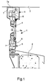
- Fig. 1 presents in a vertical cross-sectional view a glazing 4 covering the opening 1, for example a balcony glazing.
- the guide arrangement comprises an upper guide 5 and a lower guide 6 having the shape of elongated, straight profile pieces manufactured with extrusion moulding, which both contain a longitudinally directed groove 7 in each pane 4a of the glazing 4 for guiding and pivoting means 8 located on their upper and lower edges.
- the guiding and pivoting means 8 are not described in detail herein, but reference is made to prior art in the field, for example to the state of the art mentioned in the beginning of this description.
- panes 4a or the like placed on the support of the guide arrangement 5, 6, and they are arranged to move in the longitudinally directed grooves 7 of the guide arrangement supported by the guiding and pivoting means 8, wherein they can be placed at one end of the guide arrangement into a bundle-like storage position, wherein they are located side by side with in their main plane perpendicular to the longitudinal direction of the guide arrangement.
- the panes 4a, or the like are located one after the other vertically at the location of the opening 1 in the structure so that their main planes are parallel and they are placed at the location of the opening 1 in the structure and supported by the guiding and pivoting means 8 to the grooves 7 of the guide arrangement 5, 6.
- a fixing arrangement (Figs. 2a, 2b, 3, and 4) are the structure and function according to the invention implemented in connection with the lower guide 6 and thus with the lower horizontal part 2 of the opening 1, but it is obvious for a man skilled in the art that, if necessary, corresponding structures can be applied also in connection with the upper guide or with both guides in compliance with the construction and materials of the opening in a balcony or another corresponding structure.
- the upper guide is fixed via bottom 7a of the groove 7 of the upper guide profile to the upper horizontal part of the opening 1, for example to the lower surface of the bottom level 3 of an upper balcony by means of a wedged screw attachment, or the like.
- the fixing elements of the lower guide 6 comprise at least two parts in order to make possible two optional fixing methods, implemented with different fixing devices.
- the first part 9 comprises first means 10 for fixing the guide arrangement especially at the egde of the opening 1 vertically, i.e. in the case of the lower guide on top of the edge of the opening 1 (Fig. 2a).
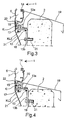
- the second part 11 comprises second means 12 for fixing the lower guide of the guide arrangement to the side of the edge of the opening 1 (Figs. 3 and 4) or alternatively at the edge of the opening 1, i.e. in the case of the lower guide on top of the edge of the opening 1 (Fig. 2b).
- the first part 9 of the fixing elements K is arranged in a direct guide arrangement attachment, wherein the first means 10 co-operate with a fixing device KL1, for example a wedged screw arrangement, which fixes the lower guide 6 of the guide arrangement at the location of the edge of the opening 1 in vertical direction, in other words in the case of the lower guide 6, on top of the edge of the opening 1.
- the first part 9 of the fixing arrangement is flange-like and is provided with a groove 9a (see Fig. 2b) or the like for forming the first means 10 (an installation hole), at which the wedged screw attachment is provided.
- the lower edge 2 of the opening 1 is in this case solid, especially concreting or the like, in which the installation hole is drilled for the fixing device KL1.
- the second part 11 of the fixing elements is primarily arranged in a so-called indirect guide arrangement attachment.
- the second means 12 are arranged for mounting a lateral fixing element 13.
- the second means 12 attach via the fixing device KL2, such as a bolt-nut arrangement or the like, the lateral fixing element 13 to the end surface 17 of the guide arrangement parallel to the installation direction.
- the lateral fixing element 13 having substantially an L-profile as its cross-sectional form, comprises third means 18, especially one or more installation holes, for mounting the guide arrangement to the side of the opening 1 so that the fixing is provided on the preferably vertical wall located in connection with the opening 1, wherein the lower guide 6 of the guide arrangement is placed either in a lower position with respect to the lower edge of the opening 1 according to Fig. 3, or in an upper position with respect to the lower edge of the opening 1 according to Fig. 3, depending on how the lateral fixing element 13 is located in the height direction.
- the second part 11 of the fixing arrangement is a profile part which comprises a groove forming the second means 12 opening in the installation direction of the guide arrangement and having preferably the cross-sectional shape of a so-called T-groove, in which the fixing device KL2 is located.
- the T-groove is preferably as long as the entire guide arrangement.
- the lateral fixing element 13 can be as long as the entire guide arrangement, or it can be composed of two or more pieces shorter than the guide arrangement.
- Fig. 2b presents an embodiment in which the lower guide 6 of the guide arrangement is fixed for example in connection with the housing-like upper edge of the balcony railing.
- the guide arrangement in the presented embodiment especially the lower guide, comprises on its edge in the installation direction a planar end surface 17, in connection with which the first 9 and the second part 11 of the fixing arrangement are placed side by side in the horizontal direction.
- the first part of the fixing arrangement is placed on the side of the guiding and pivoting means 8 viewed in the vertical direction, wherein the first part 9 forms a flange substantially perpendicular to the installation direction at the end of the guide arrangement which is parallel to the installation direction.
- the flange and its location make it possible to mount the guide arrangement from its outside completely freely.
- the second part 11 of the fixing arrangement is arranged in vertical direction at the location of the pivoting means 8.
- This location of the T-groove is especially used to fix the lateral fixing element 13 having the cross-section of an L-profile so that the horizontal fork 13a of the lateral fixing element is fixed to the second part with the fixing device KL2, wherein correspondingly the vertical fork 13b of the L-profile is fixed to the vertical side surface of the balcony railing or to a corresponding structural element, preferably to its inner surface, in a substantially vertical position.
- the guide arrangement according to the invention comprises, on the side of the vertical outer side of the guide arrangement (lower guide 6), a groove arrangement 14, 15 which, being composed of at least two parts, comprises an upper 14 groove or the like (located on the edge of the groove 7) and a lower 15 groove or the like (located between the fixing elements K and the guide structure ), which are arranged to be implemented in order to fix a cover plate 16 or a water guiding plate 19 or a corresponding structural element, applied according to the installation method of the guide arrangement in question.
- Figs. 2a, 3 and 4 present water guiding plates 19. They are typically fixed to either one of the grooves 14 or 15.
- the guide arrangement (Fig. 3) is installed in a so-called lower position with respect to the lower edge of the opening 1, in other words typically on the the upper edge of a balcony railing, so that the lower guide 6 is, viewed in horizontal direction, at least partly in lateral direction at the location of the balcony railing, the water guiding plate 19 is installed in the upper groove 14.
- Figs. 3 When the guide arrangement (Fig. 3) is installed in a so-called lower position with respect to the lower edge of the opening 1, in other words typically on the the upper edge of a balcony railing, so that the lower guide 6 is, viewed in horizontal direction, at least partly in lateral direction at the location of the balcony railing, the water guiding plate 19 is installed in the upper groove 14.
- Figs. 3 When the guide arrangement (Fig. 3) is installed in a so-called lower position with respect to the lower edge of the opening 1, in other words typically
- FIGS. 2a and 4 present situations in which the lower guide 6 of the guide arrangement is placed in its height position so that it is located at the level of the upper edge of the balcony railing or corresponding structural element, possibly slightly above that, wherein it is possible to use either one of the grooves 14, 15 intended for the installation of the water guiding plate 19, advantageously the lower groove 15, for fixing the water guiding plate 19 to the lower guide 6.
- a further advantage in the embodiments according to Figs. 2a and 4 is that holes 20 can be worked on the front edge of the groove 7 wherein moisture possibly collected inside the groove 7 exits the groove 7 via the holes 20 further along the water guiding plate 19.
- the lower guide of the guide arrangement is provided with an elongated form profile having the length of the guide arrangement, manufactured e.g. by extrusion and forming the cover plate 16.
- the cover plate 16 comprises a water guiding plate 16a located in its upper part in an oblique position, and a vertical cover plate 16b located on the front edge and fixing means 16c directed toward the lower guide 6 (the upper fixing means is preferably located in connection with the water guiding plate 16c), whereby the cover plate 16 is fixed to at least one of the grooves 14, 15 in the lower guide 6.
- an inner cover plate 21 is used, which is fixed to the installation groove located in connection with the guide arrangement 5, 6.
Landscapes
- Engineering & Computer Science (AREA)
- Mechanical Engineering (AREA)
- Civil Engineering (AREA)
- Structural Engineering (AREA)
- Steps, Ramps, And Handrails (AREA)
- Traffic Control Systems (AREA)
- Window Of Vehicle (AREA)
- Operating, Guiding And Securing Of Roll- Type Closing Members (AREA)
- Glass Compositions (AREA)
- Closing And Opening Devices For Wings, And Checks For Wings (AREA)
- Blinds (AREA)
- Organic Low-Molecular-Weight Compounds And Preparation Thereof (AREA)
- Preparation Of Compounds By Using Micro-Organisms (AREA)
- Laminated Bodies (AREA)
- Catching Or Destruction (AREA)
Claims (11)
- Agencement de guidage pour un vitrage de balcon ou équivalent, qui est prévu pour être installé dans une ouverture (1) dans une structure et pour comprendre deux ou plusieurs vitres (4a) ou équivalent, supportées sur leurs bords supérieur et inférieur horizontaux avec l'agencement de guidage (5, 6), disposées de façon mobile dans l'agencement de guidage, et prévues pour pivoter autour d'un axe de pivotement vertical jusqu'à une position de stockage sensiblement perpendiculaire à la direction longitudinale de l'agencement de guidage, depuis la position d'utilisation longitudinale de l'agencement de guidage, dans laquelle les vitres (4a) ou équivalent sont placées l'une après l'autre à l'emplacement de l'ouverture (1) dans la structure, l'agencement de guidage comportant :caractérisé en ce que les éléments de fixation (K) comportent au moins deux parties (9, 10) permettant deux variantes de procédé de fixation de l'agencement de guidage (5, 6), chaque procédé de fixation devant être mis en oeuvre avec un parmi deux variantes de dispositifs (KL1, KL2).une rainure (7) ou équivalent, dans laquelle des moyens de guidage et de pivotement (8) de chaque vitre sont disposés, etdes éléments de fixation (K) destinés à monter l'agencement de guidage (5, 6) horizontalement sur le bord (2, 3) de l'ouverture (1) dans la structure,
- Agencement de guidage selon la revendication 1, caractérisé en ce que la première partie (9) pour les éléments de fixation comporte des premiers moyens (10) pour le montage de l'agencement de guidage avec le premier dispositif de fixation (KL1), et la deuxième partie (11) comporte des seconds moyens (12) pour le montage de l'agencement de guidage avec le deuxième dispositif de fixation (KL2).
- Agencement de guidage selon la revendication 1 ou 2, caractérisé en ce que la première et/ou deuxième partie (9, 11) des éléments de fixation est disposée dans une fixation d'agencement de guidage direct (5, 6), les premiers et/ou seconds moyens (10, 12) pouvant être disposés en coopération avec le dispositif de fixation (KL1, KL2) en question afin de monter l'agencement de guidage (5, 6) à l'emplacement du bord de l'ouverture (1).
- Agencement de guidage selon la revendication 1 ou 2, caractérisé en ce qu'au moins la deuxième partie (11) des éléments de fixation est disposée dans une fixation d'agencement de guidage indirect (5, 6), les seconds moyens (12) étant disposés avec le dispositif de fixation (KL2) afin de fixer un élément de fixation latéral sur l'agencement de guidage (5, 6), l'élément de fixation latéral (13) étant pourvu de troisièmes moyens (18) pour le montage de l'agencement de guidage sur le côté de l'ouverture (1) de telle sorte que le montage est réalisé sur la paroi de préférence verticale disposée en liaison avec le bord supérieur de l'ouverture (1).
- Agencement de guidage selon la revendication 1, ayant un agencement de rainure ou équivalent pour le montage d'une plaque de recouvrement (16) et/ou d'une plaque de guidage d'eau (19) ou un élément structurel correspondant en liaison avec l'agencement de rainure, caractérisé en ce que l'agencement de rainure, ou équivalent, se compose d'au moins deux parties, comportant une rainure supérieure et une rainure inférieure (14, 15) ou équivalent, qui sont prévues pour être appliquées en fonction du procédé d'installation de l'agencement de guidage.
- Agencement de guidage selon la revendication 1, caractérisé en ce que l'agencement de guidage comprend, sur son bord dans la direction d'installation, une surface d'extrémité plane (17) en liaison avec laquelle la première (9) et la deuxième partie (11) des éléments de fixation sont disposées côte à côte.
- Agencement de guidage selon la revendication 1 ou 6, caractérisé en ce que la première partie (9) de l'agencement de fixation (K) est un rebord, en liaison avec lequel il y a une rainure longitudinale (9a) afin de former les premiers moyens (10).
- Agencement de guidage selon la revendication 1 ou 6, caractérisé en ce que la deuxième partie (11) de l'agencement de fixation est une pièce profilée, qui contient une rainure, de préférence une rainure en T, formant les seconds moyens (12).
- Agencement de guidage selon la revendication 1, 6 ou 8, caractérisé en ce que la première partie (9) de l'agencement de fixation (K), vue dans une direction verticale, est disposée sur le côté des moyens de guidage et de pivotement (8), et la deuxième partie (11) de l'agencement de fixation (K) est placée à l'emplacement des moyens de guidage et de pivotement (8).
- Agencement de guidage selon la revendication 1 ou 4, caractérisé en ce que l'élément de fixation latéral (13) a une forme en coupe d'un profilé en L.
- Agencement de guidage selon la revendication 1, caractérisé en ce que l'agencement de guidage est un guide inférieur (6), les premiers moyens (10) étant prévus pour fixer le guide inférieur (6) sur le dessus du bord de l'ouverture (1).
Applications Claiming Priority (3)
| Application Number | Priority Date | Filing Date | Title |
|---|---|---|---|
| FI973098 | 1997-07-24 | ||
| FI973098A FI973098A0 (fi) | 1997-07-24 | 1997-07-24 | Ledningsanordning i en balkongglasering eller dylikt |
| PCT/FI1998/000601 WO1999005383A1 (fr) | 1997-07-24 | 1998-07-20 | Dispositif de guidage pour le vitrage d'un balcon ou analogue |
Publications (2)
| Publication Number | Publication Date |
|---|---|
| EP0998616A1 EP0998616A1 (fr) | 2000-05-10 |
| EP0998616B1 true EP0998616B1 (fr) | 2001-10-24 |
Family
ID=8549290
Family Applications (1)
| Application Number | Title | Priority Date | Filing Date |
|---|---|---|---|
| EP98935060A Expired - Lifetime EP0998616B1 (fr) | 1997-07-24 | 1998-07-20 | Dispositif de guidage pour le vitrage d'un balcon ou analogue |
Country Status (8)
| Country | Link |
|---|---|
| EP (1) | EP0998616B1 (fr) |
| AT (1) | ATE207576T1 (fr) |
| AU (1) | AU8444398A (fr) |
| DE (1) | DE69802194T2 (fr) |
| DK (1) | DK0998616T3 (fr) |
| FI (1) | FI973098A0 (fr) |
| NO (1) | NO313206B1 (fr) |
| WO (1) | WO1999005383A1 (fr) |
Families Citing this family (2)
| Publication number | Priority date | Publication date | Assignee | Title |
|---|---|---|---|---|
| SE536764C2 (sv) * | 2012-04-23 | 2014-07-22 | Nordiska Balco Ab | Hållanordning för fasthållning av ett i en balkonginglasningingående ramelement |
| FI124409B (fi) | 2013-04-02 | 2014-08-15 | Alutec Oy | Parvekekaiteen alaprofiili |
Family Cites Families (7)
| Publication number | Priority date | Publication date | Assignee | Title |
|---|---|---|---|---|
| US3879799A (en) * | 1973-05-03 | 1975-04-29 | Hough Mfg Corp | Multidirectional suspension system for operable partitions |
| FR2545143B1 (fr) * | 1983-04-27 | 1988-02-05 | Saint Gobain Vitrage | Vitrage de baies de grande surface |
| ES2038942A6 (es) * | 1989-04-11 | 1993-08-01 | Lemminkainen Oy Y Otros | Disposicion de barras de deslizamiento para acristalado de balcones o terrazas y disposicion de soporte para los paneles de cristal, para la realizacion de la disposicion de barras de deslizamiento. |
| FI90796C (fi) * | 1992-04-08 | 1994-03-25 | Lahden Parvekelasitus Oy | Kääntyvä lasitus |
| FI92517C (fi) * | 1992-10-14 | 1994-11-25 | Jarmo Sjoeholm | Liukuelementtijärjestelmä |
| SE504736C2 (sv) * | 1992-11-02 | 1997-04-14 | Bo Flygare | Inbyggnad vid balkonger |
| FI950522A0 (fi) * | 1995-02-07 | 1995-02-07 | Lumon Oy | System foer montering av ett skivartat stycke saerskilt inglasning av en balkong |
-
1997
- 1997-07-24 FI FI973098A patent/FI973098A0/fi not_active Application Discontinuation
-
1998
- 1998-07-20 WO PCT/FI1998/000601 patent/WO1999005383A1/fr not_active Ceased
- 1998-07-20 DE DE69802194T patent/DE69802194T2/de not_active Expired - Fee Related
- 1998-07-20 EP EP98935060A patent/EP0998616B1/fr not_active Expired - Lifetime
- 1998-07-20 AT AT98935060T patent/ATE207576T1/de not_active IP Right Cessation
- 1998-07-20 AU AU84443/98A patent/AU8444398A/en not_active Abandoned
- 1998-07-20 DK DK98935060T patent/DK0998616T3/da active
-
2000
- 2000-01-11 NO NO20000143A patent/NO313206B1/no not_active IP Right Cessation
Also Published As
| Publication number | Publication date |
|---|---|
| NO20000143D0 (no) | 2000-01-11 |
| DE69802194T2 (de) | 2002-06-06 |
| AU8444398A (en) | 1999-02-16 |
| NO313206B1 (no) | 2002-08-26 |
| WO1999005383A1 (fr) | 1999-02-04 |
| EP0998616A1 (fr) | 2000-05-10 |
| FI973098A0 (fi) | 1997-07-24 |
| DE69802194D1 (de) | 2001-11-29 |
| NO20000143L (no) | 2000-01-11 |
| DK0998616T3 (da) | 2002-02-18 |
| ATE207576T1 (de) | 2001-11-15 |
Similar Documents
| Publication | Publication Date | Title |
|---|---|---|
| US6647590B2 (en) | Fixing device for a rail | |
| CA2501911C (fr) | Mur-rideau integre et systeme de distribution de goulottes guide-fils | |
| US4335550A (en) | Prime window unit installation system | |
| CN211499361U (zh) | 一种幕墙安装结构 | |
| US11512521B2 (en) | Dry install receptor system | |
| GB2128666A (en) | Window drain | |
| EP0808404B1 (fr) | Dispositif de montage pour pieces planes et en particulier pour vitres de balcons | |
| EP0998616A1 (fr) | Dispositif de guidage pour le vitrage d'un balcon ou analogue | |
| US2731118A (en) | Means for mounting windows or other components in buildings | |
| KR200272005Y1 (ko) | 창호 조립체 | |
| KR200451121Y1 (ko) | 코킹 일체형 건축물의 외장재 고정장치 | |
| CN110409681B (zh) | 一种幕墙窗的建造方法 | |
| EP2644812B1 (fr) | Système de vitrage ou similaire | |
| KR101267777B1 (ko) | 방화유리창, 방화유리창이 설치된 발코니 난간 및 그 시공방법 | |
| FI105712B (fi) | Julkisivun viimeistelyjärjestelmä | |
| GB2159202A (en) | Prefabricated facade | |
| CN222667042U (zh) | 一种可开启的封闭阳台结构、系统及建筑 | |
| JP7815010B2 (ja) | 換気ダクトユニット | |
| KR102855368B1 (ko) | 중중연창 방식 미서기창호 연결구 | |
| EP1442194B1 (fr) | Structure d'etancheite pour systeme de vitrage | |
| EP1446545B1 (fr) | Structure surbaissee pour systeme de vitrage | |
| CN110306703B (zh) | 一种玻璃幕墙窗 | |
| KR200449147Y1 (ko) | 방화유리창 및 방화유리창이 설치된 발코니 난간 | |
| ITMI20090906A1 (it) | Struttura per il montaggio di pareti | |
| GB2191529A (en) | Window frame |
Legal Events
| Date | Code | Title | Description |
|---|---|---|---|
| PUAI | Public reference made under article 153(3) epc to a published international application that has entered the european phase |
Free format text: ORIGINAL CODE: 0009012 |
|
| 17P | Request for examination filed |
Effective date: 20000203 |
|
| AK | Designated contracting states |
Kind code of ref document: A1 Designated state(s): AT BE CH DE DK FI FR GB LI NL SE |
|
| GRAG | Despatch of communication of intention to grant |
Free format text: ORIGINAL CODE: EPIDOS AGRA |
|
| GRAG | Despatch of communication of intention to grant |
Free format text: ORIGINAL CODE: EPIDOS AGRA |
|
| GRAH | Despatch of communication of intention to grant a patent |
Free format text: ORIGINAL CODE: EPIDOS IGRA |
|
| 17Q | First examination report despatched |
Effective date: 20010314 |
|
| GRAH | Despatch of communication of intention to grant a patent |
Free format text: ORIGINAL CODE: EPIDOS IGRA |
|
| GRAA | (expected) grant |
Free format text: ORIGINAL CODE: 0009210 |
|
| AK | Designated contracting states |
Kind code of ref document: B1 Designated state(s): AT BE CH DE DK FI FR GB LI NL SE |
|
| REF | Corresponds to: |
Ref document number: 207576 Country of ref document: AT Date of ref document: 20011115 Kind code of ref document: T |
|
| REG | Reference to a national code |
Ref country code: CH Ref legal event code: EP |
|
| REG | Reference to a national code |
Ref country code: CH Ref legal event code: NV Representative=s name: PATENTANWAELTE FELDMANN & PARTNER AG |
|
| REF | Corresponds to: |
Ref document number: 69802194 Country of ref document: DE Date of ref document: 20011129 |
|
| REG | Reference to a national code |
Ref country code: GB Ref legal event code: IF02 |
|
| REG | Reference to a national code |
Ref country code: DK Ref legal event code: T3 |
|
| ET | Fr: translation filed | ||
| PLBE | No opposition filed within time limit |
Free format text: ORIGINAL CODE: 0009261 |
|
| STAA | Information on the status of an ep patent application or granted ep patent |
Free format text: STATUS: NO OPPOSITION FILED WITHIN TIME LIMIT |
|
| 26N | No opposition filed | ||
| REG | Reference to a national code |
Ref country code: CH Ref legal event code: PFA Owner name: LUMON OY Free format text: LUMON OY#KAITILANKATU 7#45130 KOUVOLA (FI) -TRANSFER TO- LUMON OY#KAITILANKATU 7#45130 KOUVOLA (FI) |
|
| PGFP | Annual fee paid to national office [announced via postgrant information from national office to epo] |
Ref country code: DK Payment date: 20080716 Year of fee payment: 11 Ref country code: DE Payment date: 20080719 Year of fee payment: 11 |
|
| PGFP | Annual fee paid to national office [announced via postgrant information from national office to epo] |
Ref country code: NL Payment date: 20080715 Year of fee payment: 11 Ref country code: FR Payment date: 20080715 Year of fee payment: 11 Ref country code: FI Payment date: 20080711 Year of fee payment: 11 Ref country code: AT Payment date: 20080721 Year of fee payment: 11 |
|
| PGFP | Annual fee paid to national office [announced via postgrant information from national office to epo] |
Ref country code: GB Payment date: 20080714 Year of fee payment: 11 |
|
| PGFP | Annual fee paid to national office [announced via postgrant information from national office to epo] |
Ref country code: CH Payment date: 20081024 Year of fee payment: 11 |
|
| PGFP | Annual fee paid to national office [announced via postgrant information from national office to epo] |
Ref country code: SE Payment date: 20080717 Year of fee payment: 11 Ref country code: BE Payment date: 20080729 Year of fee payment: 11 |
|
| BERE | Be: lapsed |
Owner name: *LUMON OY Effective date: 20090731 |
|
| REG | Reference to a national code |
Ref country code: CH Ref legal event code: PL |
|
| REG | Reference to a national code |
Ref country code: DK Ref legal event code: EBP |
|
| EUG | Se: european patent has lapsed | ||
| GBPC | Gb: european patent ceased through non-payment of renewal fee |
Effective date: 20090720 |
|
| NLV4 | Nl: lapsed or anulled due to non-payment of the annual fee |
Effective date: 20100201 |
|
| REG | Reference to a national code |
Ref country code: FR Ref legal event code: ST Effective date: 20100331 |
|
| PG25 | Lapsed in a contracting state [announced via postgrant information from national office to epo] |
Ref country code: LI Free format text: LAPSE BECAUSE OF NON-PAYMENT OF DUE FEES Effective date: 20090731 Ref country code: FR Free format text: LAPSE BECAUSE OF NON-PAYMENT OF DUE FEES Effective date: 20090731 Ref country code: FI Free format text: LAPSE BECAUSE OF NON-PAYMENT OF DUE FEES Effective date: 20090720 Ref country code: CH Free format text: LAPSE BECAUSE OF NON-PAYMENT OF DUE FEES Effective date: 20090731 |
|
| PG25 | Lapsed in a contracting state [announced via postgrant information from national office to epo] |
Ref country code: GB Free format text: LAPSE BECAUSE OF NON-PAYMENT OF DUE FEES Effective date: 20090720 |
|
| PG25 | Lapsed in a contracting state [announced via postgrant information from national office to epo] |
Ref country code: DE Free format text: LAPSE BECAUSE OF NON-PAYMENT OF DUE FEES Effective date: 20100202 Ref country code: BE Free format text: LAPSE BECAUSE OF NON-PAYMENT OF DUE FEES Effective date: 20090731 Ref country code: AT Free format text: LAPSE BECAUSE OF NON-PAYMENT OF DUE FEES Effective date: 20090720 |
|
| PG25 | Lapsed in a contracting state [announced via postgrant information from national office to epo] |
Ref country code: DK Free format text: LAPSE BECAUSE OF NON-PAYMENT OF DUE FEES Effective date: 20090731 |
|
| PG25 | Lapsed in a contracting state [announced via postgrant information from national office to epo] |
Ref country code: SE Free format text: LAPSE BECAUSE OF NON-PAYMENT OF DUE FEES Effective date: 20090721 |
|
| PG25 | Lapsed in a contracting state [announced via postgrant information from national office to epo] |
Ref country code: NL Free format text: LAPSE BECAUSE OF NON-PAYMENT OF DUE FEES Effective date: 20100201 |