EP0999534B1 - Simulateur d'entraînement - Google Patents
Simulateur d'entraînement Download PDFInfo
- Publication number
- EP0999534B1 EP0999534B1 EP99118219A EP99118219A EP0999534B1 EP 0999534 B1 EP0999534 B1 EP 0999534B1 EP 99118219 A EP99118219 A EP 99118219A EP 99118219 A EP99118219 A EP 99118219A EP 0999534 B1 EP0999534 B1 EP 0999534B1
- Authority
- EP
- European Patent Office
- Prior art keywords
- simulator according
- module
- image
- projection
- cab
- Prior art date
- Legal status (The legal status is an assumption and is not a legal conclusion. Google has not performed a legal analysis and makes no representation as to the accuracy of the status listed.)
- Expired - Lifetime
Links
- 238000004519 manufacturing process Methods 0.000 claims description 3
- 229920003023 plastic Polymers 0.000 claims description 3
- 239000002184 metal Substances 0.000 abstract 1
- 230000033001 locomotion Effects 0.000 description 5
- 238000009434 installation Methods 0.000 description 3
- 230000001133 acceleration Effects 0.000 description 2
- 238000005538 encapsulation Methods 0.000 description 2
- 230000008447 perception Effects 0.000 description 2
- 238000004088 simulation Methods 0.000 description 2
- 230000006978 adaptation Effects 0.000 description 1
- 230000005540 biological transmission Effects 0.000 description 1
- 230000015572 biosynthetic process Effects 0.000 description 1
- 238000010276 construction Methods 0.000 description 1
- 238000012937 correction Methods 0.000 description 1
- 230000003247 decreasing effect Effects 0.000 description 1
- 238000011161 development Methods 0.000 description 1
- 230000018109 developmental process Effects 0.000 description 1
- 230000000694 effects Effects 0.000 description 1
- 230000003137 locomotive effect Effects 0.000 description 1
- 238000002156 mixing Methods 0.000 description 1
- 238000000926 separation method Methods 0.000 description 1
- 230000007704 transition Effects 0.000 description 1
Images


Classifications
-
- G—PHYSICS
- G09—EDUCATION; CRYPTOGRAPHY; DISPLAY; ADVERTISING; SEALS
- G09B—EDUCATIONAL OR DEMONSTRATION APPLIANCES; APPLIANCES FOR TEACHING, OR COMMUNICATING WITH, THE BLIND, DEAF OR MUTE; MODELS; PLANETARIA; GLOBES; MAPS; DIAGRAMS
- G09B9/00—Simulators for teaching or training purposes
- G09B9/02—Simulators for teaching or training purposes for teaching control of vehicles or other craft
- G09B9/04—Simulators for teaching or training purposes for teaching control of vehicles or other craft for teaching control of land vehicles
- G09B9/05—Simulators for teaching or training purposes for teaching control of vehicles or other craft for teaching control of land vehicles the view from a vehicle being simulated
Definitions
- the invention relates to an exercise simulator for training of persons in the leadership of vehicles, especially commercial vehicles, the type specified in the preamble of claim 1.
- the projection screen is composed of flat individual surfaces that connect along a complete the driver's cab from the front polygon seamlessly.
- the individual surfaces are held by means of a frame consisting of a vertical holding mast and a horizontal guide rail mounted on the ground.
- the image projectors, each illuminating a single area of the projection screen, are divided into two groups.
- the image projectors for the middle individual areas are arranged in the apparent direction of travel behind the projection screen. The outgoing from these projectors light bundle hit by arranged in the individual areas passages on the passages associated deflection mirror and fall onto the screen in front of the driver's cab.
- the image projectors for the further outlying individual surfaces are arranged above the driver's cab and their light bundles fall over deflecting mirrors mounted on the roof of the driver's cabin onto the vehicle Projection screen.
- This reflected light projection has the disadvantage that when using a usually required, original driver's cab and the adaptation of the simulated environment to the driver's field of view because of the large dimensions of the cab and the extreme dimensions of the field of view, a shadow-proof projection can only be achieved if the screen far away from the driver's cab and the projectors are placed high above the driver's cab.
- This requires large dimensions of the driving simulator which on the one hand requires high buildings to accommodate it and on the other hand, the placement of the simulator on a motion system, eg for acceleration simulation, considerably more difficult.
- three large-screen projectors are provided for the representation of the simulated environment, which represent by means of transmitted light projection portions of the visible panorama on one of three trapezoidal in front of the driver's cab, transparent projection screens.
- the large-screen projectors are arranged on the rear side of the projection screens facing away from the driver's cab, and each large-screen projector projects a sector of a panorama extending over 180 ° onto the rear side of the projection screen via a deflection mirror.
- Transmitted light or rear projection has the advantage that the light paths for image generation and image perception are strictly separated and thereby the projection screen can be brought closer to the driver's cab, resulting in smaller dimensions of the simulator and brighter images.
- the disadvantage is that the projection screens are relatively unstable and are also not suitable for mounting on a movement system.
- the invention has for its object to provide an exercise simulator of the type mentioned with low height and small width, in which without significant design changes to the vehicle adapted to different fields of vision on the projection screen can be designed and the image display system has a high mechanical stability, so that the simulator, eg for acceleration simulation, can also be installed on a motion system.
- the exercise simulator according to the invention has the advantage that the projection screen has a high stability by the one-piece, by clamping in the brackets cylindrically curved transparent plastic transparency, which even meets the requirements of installation on a movement system.
- the transmission lens By maintaining the transmitted light projection the strict separation of the light paths for the image production and perception is given, so that on the one hand the transmission lens can be arranged relatively close to the driver's cabin and on the other hand, the image projectors can be placed near the ground and thus small overall dimensions for the exercise simulator can be achieved.
- the field of view can be adapted to the extent required by the field of vision required for the respective training vehicle.
- the translucent lens poses no special requirement for production and transport, since it is flat and only curved during its assembly. The assembly is simple and not very time-consuming, as it only in the on a circular arc arranged brackets must be used, which clamp the transmitted-light disk at its upper and lower edges.
- each holder is formed on a mounting module, and the modules are circular segment-shaped so that they can be connected to each other to form a partially or fully closed cylinder and firmly connected to each other.
- This modular design offers the possibility to adapt the projection screen in the horizontal direction to the field of view required for the special simulator by simply adding or removing modules.
- the size of the translucent lens in the horizontal direction must be dimensioned in each case according to the field of view, which is done by replacing transmitted-light discs.
- the modules are preferably designed so that each module covers a circle segment of 30 °, the modules extend over the entire vertical height of the translucent disk and the holder on each module clamps the transmitted-light disk at its upper and lower edges.
- the modules are designed so that they can be mounted either alone or on a movement system.
- an image projector and a deflection mirror for folding the outgoing from the projector projection beam is arranged in each module, wherein the image projector and deflecting mirror are aligned so that an incident along the projector axis beam is reflected by the deflection mirror so that he hits the translucent lens at right angles.
- Each image projector illuminates a field of 33 ° in the horizontal direction on the transmitted-light disk in order to obtain so-called edge blending, ie a gradual transition from one field to another, for a segment width of 30 °.
- edge blending ie a gradual transition from one field to another, for a segment width of 30 °.
- the holder of the translucent lens is radially adjustable on each module, wherein each holder is preferably by the top and bottom of the module attachable, each receiving a receptacle for the translucent screen adapter of different lengths in the radial direction is gradually extended.
- the cylinder radius of the translucent disk can be reduced according to the selected length of the adapter, which increases the vertical field of view for the driver in the driver's cab. The reduction of the cylinder radius simultaneously provides the additionally required projection distance, so that the outer diameter of the image display system remains constant.
- the image projectors are equipped with a wide-angle lens, which provides a ratio of the long image side to the projection distance of 1: 1.2 or greater.
- the projection distance between the image projector and the projection screen which is already short by the deflecting mirrors, can be further shortened, which has an advantageous effect on the outside diameter of the image display system.
- the picture tubes of each image projector are rotated so that a vertically erected image is projected at horizontal projector position. This gives a fairly flat design of the image projectors, so that as much free space in the area in which the light rays run, is obtained.
- each image projector also has a housing containing the picture tubes and a housing containing the electronics, wherein the electronics housing is arranged outside the space bounded by the transmitted-light disk and the deflection mirror.
- the circularly arranged modules receive at their upper edge a cover which spans the space remaining between the modules. This encapsulation of the entire exercise simulator is achieved, so that it is not necessary to darken the installation space of the exercise simulator.
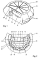
- the exercise simulator for training truck drivers in the guidance of trucks which can be seen in section in FIG. 1 in a perspective representation and in FIG. 2, as an exemplary embodiment of a general exercise simulator for training persons in the guidance of any vehicles, has a driver's cab 10. which is simulated in the case of the truck simulator an original cab of a truck.
- the driver and front passenger seats 11 and 12 and the two outer rearview mirrors are denoted by 13 and 14 in the cab 10.
- a projection screen 15 of an image display system 16 is set up, on which a simulated environment visible from the driver's cab 10 is displayed.
- the simulated environment visible on the projection screen 15 is composed of a plurality of individual images which are projected onto the rear side of the projection screen 15 by a plurality of image projectors 17 in a so-called transmitted light or back projection.
- the image display system 16 arranged around the driver's cab 10 further comprises a plurality of individual mounting modules 18 which are circular-segment-shaped are formed so that they can be lined up to form a partially closed cylinder and firmly connected to each other.
- the formation of a fully closed cylinder for displaying a panoramic view is possible.
- the image display system 16 is composed of a total of eight modules 18, each covering a circle segment of 30 °, so that the image display system 16 extends over 240 ° horizontally around the driver's cab 10 around.
- a module 18 is shown schematically in FIG. 3 in a perspective view and in FIG. 4 in a longitudinal section.
- Each module 18 has a box-shaped module housing 19 which contains a holder 20 for the projection screen 15, an image projector 17 arranged in the foot area and a deflection mirror 21 which folds the projection beam of the image projector 17.
- Image projector 17 and deflecting mirror 21 are arranged within the module housing 19 so that an incident along the projector axis projection beam from the deflecting mirror 21 is reflected so that it impinges at right angles to the projection screen 15.
- Each image projector 17 has a housing 23 containing three color picture tubes 22 and a housing 24 containing the electronics, which is arranged in front of the module 18 between the picture tube housing 23 and the projection screen 15 in order to maximize the free space for the projection beams.
- the picture tubes 22 are rotated so that when horizontal position of the housing 23, a vertical image is projected.
- the image projectors 17 are equipped with a wide-angle lens that provides a ratio of the long image width to the projection distance of 1: 1.2 or greater.
- each holder 20 consists of an upper and lower retaining ring 201 and 202, (FIG. 4), which overlap each with a receptacle 28, the transmitted-light disk 25 at the upper and lower edge of the disc.
- the modules 18 receive at their upper edge a cover 29 (Fig. 1) which is formed so that it spans the remaining between the modules 18 interior space.
- the modular design of the image display system 16 makes it possible to use the exercise simulator for different types of vehicles, e.g. As trucks, trams, locomotives, railcars, etc., and thereby easily adjust the image display system 16 to the required in the respective vehicle field of view from the driver's cab. So z. B. for a truck a field of view of vertically 30 ° down and 10 ° upwards required and horizontal 120 ° to the left and 90 ° to the right. For a tram, however, a field of view must have a viewing angle of vertically each 27 ° up and down and a viewing angle in the horizontal of about 105 ° to the right and left.
- vehicles e.g. As trucks, trams, locomotives, railcars, etc.
- the horizontal field of view can be increased or decreased by adding or removing one or more modules 18, wherein the transparent translucent lens 25 must be replaced by a longer or shorter disc.
- the vertical field of view can be increased by reducing the cylinder radius of the transmitted light disk 25. This is achieved - as illustrated in Fig. 4 - achieved in that the brackets 20 are formed on the modules 18 in the radial direction gradually adjustable. In the embodiment, this can be attached to the module 18 upper and lower adapter 26, 27 and 26 ', 27' are provided, the same receptacles 28 for the upper and lower disc edge as the retaining rings 201 and 202 on the module housing 19.
- the transmitted light disk 25 To reduce the cylinder radius the transmitted light disk 25, these adapters 26, 27 and 26 ', 27' attached to the top and bottom of the module housing 19, and the transmitted-light disk 25 is inserted into the receptacles 28.
- the ⁇ 1 , ⁇ 2 and ⁇ 3 designate the vertical angles of the various fields of view, which are displayed on the translucent lens 25 at a cylinder radius R 1 , R 2 and R 3 of the translucent lens 25.
- the modules 18 are arranged on a circular arc with a larger radius by being deducted from each other and are used in the gaps between them not shown here adapter pieces that connect the adjacent modules 18 together. However, this also increases the outer diameter of the entire exercise simulator.
Landscapes
- Engineering & Computer Science (AREA)
- Theoretical Computer Science (AREA)
- Aviation & Aerospace Engineering (AREA)
- Business, Economics & Management (AREA)
- Physics & Mathematics (AREA)
- Educational Administration (AREA)
- Educational Technology (AREA)
- General Physics & Mathematics (AREA)
- Projection Apparatus (AREA)
- Lenses (AREA)
- Gyroscopes (AREA)
- Steroid Compounds (AREA)
Claims (12)
- Simulateur d'entraînement pour former des personnes à la conduite de véhicules, en particulier de véhicules utilitaires, avec une cabine de conduite (10) et avec un système de visualisation (16) pour produire un environnement simulé visible depuis la cabine de conduite (10), système qui présente un écran de projection (15) installé devant la cabine de conduite (10) et plusieurs projecteurs d'images (17) pour projeter des images composant l'environnement simulé sur le côté arrière, opposé à la cabine de conduite (10), de l'écran de projection (15), caractérisé en ce que l'écran de projection (15) est une vitre (25) à éclairage par transmission, plane et d'un seul tenant, en matière plastique transparente, qui est courbée cylindriquement au moyen de supports (20) fixés en position en arc de cercle.
- Simulateur selon la revendication 1, caractérisé en ce que chaque support (20) est formé sur un module de montage (18), et en ce que les modules (18) sont réalisés en forme de segments de cercle de telle sorte qu'ils peuvent être juxtaposés pour former un cylindre partiellement ou totalement fermé, et fixement reliés entre eux.
- Simulateur selon la revendication 2, caractérisé en ce que le module (18) s'étend sur toute la hauteur verticale de la vitre (25) à éclairage par transmission et les supports (20) enserrent la vitre (25) à éclairage par transmission le long de son bord supérieur et de son bord inférieur.
- Simulateur selon la revendication 3, caractérisé en ce que chaque support (20) d'un module (18) présente deux bagues de support (201, 202) qui engagent en recouvrement la vitre (25) à éclairage par transmission sur son bord supérieur et son bord inférieur.
- Simulateur selon l'une quelconque des revendications 2 à 4, caractérisé en ce que chaque module (18) couvre un segment de cercle de 30°.
- Simulateur selon l'une quelconque des revendications 2 à 5, caractérisé en ce que le support (20) pour la vitre (25) à éclairage par transmission est réalisé avec possibilité de réglage radial sur chaque module (18), de préférence graduellement.
- Simulateur selon la revendication 6, caractérisé en ce que chaque support (20) peut être prolongé graduellement en direction radiale par des adaptateurs (26, 27 ; 26', 27') de longueurs différentes pouvant être rapportés en haut et en bas sur le module (18) et présentant chacun une partie réceptrice (28) pour la vitre (25) à éclairage par transmission.
- Simulateur selon l'une quelconque des revendications 1 à 7, caractérisé en ce qu'un projecteur d'images (17) et un miroir de renvoi (21) pour renvoyer le faisceau de projection provenant du projecteur d'images (17) sont disposés dans chaque module (18), et en ce que le projecteur d'images (17) et le miroir de renvoi (21) sont orientés de telle sorte qu'un faisceau de projection incident le long de l'axe du projecteur est réfléchi par le miroir de renvoi (21) de telle sorte qu'il atteint perpendiculairement la vitre (25) à éclairage par transmission.
- Simulateur selon l'une quelconque des revendications 1 à 8, caractérisé en ce que les projecteurs d'images (17) sont équipés d'un objectif grand-angulaire qui fournit un rapport de 1:1,2 entre le grand côté de l'image et la distance de projection.
- Simulateur selon la revendication 8 ou 9, caractérisé en ce que les tubes images (22) des projecteurs d'images (17) sont tournés de telle sorte qu'une image redressée verticalement est projetée lorsque le projecteur est en position horizontale.
- Simulateur selon l'une quelconque des revendications 1 à 10, caractérisé en ce que chaque projecteur d'images (17) présente un boîtier (23) contenant les tubes images (22) et un boîtier (24) contenant l'équipement électronique (23), et en ce que le boîtier électronique (24) est disposé en dehors de l'espace délimité dans le module (18) par la vitre (25) à éclairage par transmission et le miroir de renvoi (21).
- Simulateur selon l'une quelconque des revendications 2 à 11, caractérisé en ce que les modules (18) juxtaposés circulairement reçoivent sur leur bord supérieur un élément de recouvrement (29) qui couvre l'espace intérieur circonscrit par les modules (18).
Applications Claiming Priority (2)
| Application Number | Priority Date | Filing Date | Title |
|---|---|---|---|
| DE19850406A DE19850406C1 (de) | 1998-11-02 | 1998-11-02 | Übungssimulator |
| DE19850406 | 1998-11-02 |
Publications (3)
| Publication Number | Publication Date |
|---|---|
| EP0999534A2 EP0999534A2 (fr) | 2000-05-10 |
| EP0999534A3 EP0999534A3 (fr) | 2006-01-11 |
| EP0999534B1 true EP0999534B1 (fr) | 2007-02-28 |
Family
ID=7886379
Family Applications (1)
| Application Number | Title | Priority Date | Filing Date |
|---|---|---|---|
| EP99118219A Expired - Lifetime EP0999534B1 (fr) | 1998-11-02 | 1999-09-14 | Simulateur d'entraînement |
Country Status (3)
| Country | Link |
|---|---|
| EP (1) | EP0999534B1 (fr) |
| AT (1) | ATE355580T1 (fr) |
| DE (2) | DE19850406C1 (fr) |
Families Citing this family (2)
| Publication number | Priority date | Publication date | Assignee | Title |
|---|---|---|---|---|
| DE10302409A1 (de) * | 2003-01-21 | 2004-08-05 | Rheinmetall Defence Electronics Gmbh | Verfahren zur Bilddarstellung |
| US7708561B2 (en) | 2005-09-23 | 2010-05-04 | Q4 Services Llc | Method and apparatus for modifying aircraft simulator wide-angled infinity display equipment mirror to enlarge field of vision and for reskinning aircraft simulator spherical mirror cell to minimize mirror stress and distortion |
Family Cites Families (5)
| Publication number | Priority date | Publication date | Assignee | Title |
|---|---|---|---|---|
| FR2636459B1 (fr) * | 1988-09-09 | 1990-10-19 | Thomson Csf | Systeme de restitution de l'environnement visuel d'un pilote en simulateur |
| DE3925427C2 (de) * | 1989-08-01 | 2000-01-13 | Wegmann & Co Gmbh | Fahrsimulator, insbesondere zur Ausbildung an Lastkraftwagen |
| DE4438411A1 (de) * | 1994-10-27 | 1996-05-02 | Stn Atlas Elektronik Gmbh | Übungseinrichtung |
| JPH08248872A (ja) * | 1995-03-08 | 1996-09-27 | Toyota Motor Corp | 運転模擬試験装置 |
| JP2781755B2 (ja) * | 1995-10-04 | 1998-07-30 | 東芝テスコ株式会社 | 乗物シミュレータ用ドームスクリーン |
-
1998
- 1998-11-02 DE DE19850406A patent/DE19850406C1/de not_active Expired - Fee Related
-
1999
- 1999-09-14 EP EP99118219A patent/EP0999534B1/fr not_active Expired - Lifetime
- 1999-09-14 DE DE59914219T patent/DE59914219D1/de not_active Expired - Lifetime
- 1999-09-14 AT AT99118219T patent/ATE355580T1/de not_active IP Right Cessation
Also Published As
| Publication number | Publication date |
|---|---|
| DE59914219D1 (de) | 2007-04-12 |
| EP0999534A2 (fr) | 2000-05-10 |
| ATE355580T1 (de) | 2006-03-15 |
| DE19850406C1 (de) | 2000-01-13 |
| EP0999534A3 (fr) | 2006-01-11 |
Similar Documents
| Publication | Publication Date | Title |
|---|---|---|
| DE19851000C2 (de) | Projektionsanordnung | |
| DE2323696A1 (de) | Optisches system zur erweiterung des gesichtsfeldes | |
| EP3807705B1 (fr) | Affichage tête haute destiné à un véhicule | |
| DE102018209934A1 (de) | Blickfeldanzeigevorrichtung für ein Kraftfahrzeug | |
| EP0309528A1 (fr) | Systeme d'affichage stereoscopique. | |
| EP3834031B1 (fr) | Procédé pour faire fonctionner un dispositif d'affichage de champ de vision pour un véhicule automobile | |
| DE102019210718A1 (de) | Anzeigevorrichtung mit einem Sichtschutzelement, und Kraftfahrzeug mit einer Anzeigevorrichtung | |
| DE102017216525A1 (de) | Head-up-Anzeigevorrichtung für ein Kraftfahrzeug | |
| DE102019127406A1 (de) | Kraftfahrzeug mit einer Umfeldbeleuchtungseinrichtung | |
| EP0356891A2 (fr) | Miroir périscopique changeable | |
| DE2009200A1 (de) | Anzeigevorrichtung zur Wiedergabe von relativ zueinander bewegbaren Symbolen | |
| EP0999534B1 (fr) | Simulateur d'entraînement | |
| DE3925427C2 (de) | Fahrsimulator, insbesondere zur Ausbildung an Lastkraftwagen | |
| DE102018200498A1 (de) | Anzeigevorrichtung und Verfahren zur Projizierung eines Bildes auf eine virtuelle Position während einer Fahrt eines Fahrzeuges | |
| DE102019134514A1 (de) | Kraftfahrzeug mit einem Head-up-Display, Verfahren zum Betreiben einer Anzeigevorrichtung mit einem Head-up-Display, und Steuereinrichtung | |
| DE102019108330A1 (de) | Faltbare Blickfeldanzeigevorrichtung | |
| DE19907345B4 (de) | Vorrichtung zum Abbilden eines als Raster von Bildpunkten darstellbaren Bildes auf einem Schirm | |
| DE102017204435A1 (de) | Anordnung zur fahrsituativen Simulation von Blendungseffekten oder blendungsähnlichen Effekten | |
| DE112019002608T5 (de) | Head-up-Display-Vorrichtung | |
| DE4103845A1 (de) | Projektionsvorrichtung fuer planetarien | |
| DE102019122417A1 (de) | Kompakte Blickfeldanzeigevorrichtung | |
| DE102018204958B4 (de) | Anzeigeeinrichtung zur Projektion eines Bilds auf eine Scheibe eines Kraftfahrzeugs sowie Verfahren zum Betreiben einer Anzeigeeinrichtung | |
| DE102023105899A1 (de) | Head-Up-Display mit einer platzsparenden Displayanordnung, insbesondere für ein Fahrzeug | |
| DE202006020591U1 (de) | Head-Up-Display-System für Kraftfahrzeuge | |
| DE102023125318A1 (de) | Hybrid-HUD zur erweiterten AR-Anzeige und vereinfachten Integration in einem Fahrzeug |
Legal Events
| Date | Code | Title | Description |
|---|---|---|---|
| PUAI | Public reference made under article 153(3) epc to a published international application that has entered the european phase |
Free format text: ORIGINAL CODE: 0009012 |
|
| AK | Designated contracting states |
Kind code of ref document: A2 Designated state(s): AT BE CH CY DE DK ES FI FR GB GR IE IT LI LU MC NL PT SE |
|
| AX | Request for extension of the european patent |
Free format text: AL;LT;LV;MK;RO;SI |
|
| RAP1 | Party data changed (applicant data changed or rights of an application transferred) |
Owner name: RHEINMETALL DEFENCE ELECTRONICS GMBH |
|
| PUAL | Search report despatched |
Free format text: ORIGINAL CODE: 0009013 |
|
| AK | Designated contracting states |
Kind code of ref document: A3 Designated state(s): AT BE CH CY DE DK ES FI FR GB GR IE IT LI LU MC NL PT SE |
|
| AX | Request for extension of the european patent |
Extension state: AL LT LV MK RO SI |
|
| 17P | Request for examination filed |
Effective date: 20060616 |
|
| AKX | Designation fees paid |
Designated state(s): AT BE CH CY DE DK ES FI FR GB GR IE IT LI LU MC NL PT SE |
|
| GRAP | Despatch of communication of intention to grant a patent |
Free format text: ORIGINAL CODE: EPIDOSNIGR1 |
|
| GRAS | Grant fee paid |
Free format text: ORIGINAL CODE: EPIDOSNIGR3 |
|
| GRAA | (expected) grant |
Free format text: ORIGINAL CODE: 0009210 |
|
| AK | Designated contracting states |
Kind code of ref document: B1 Designated state(s): AT BE CH CY DE DK ES FI FR GB GR IE IT LI LU MC NL PT SE |
|
| PG25 | Lapsed in a contracting state [announced via postgrant information from national office to epo] |
Ref country code: IE Free format text: LAPSE BECAUSE OF FAILURE TO SUBMIT A TRANSLATION OF THE DESCRIPTION OR TO PAY THE FEE WITHIN THE PRESCRIBED TIME-LIMIT Effective date: 20070228 Ref country code: FI Free format text: LAPSE BECAUSE OF FAILURE TO SUBMIT A TRANSLATION OF THE DESCRIPTION OR TO PAY THE FEE WITHIN THE PRESCRIBED TIME-LIMIT Effective date: 20070228 Ref country code: DK Free format text: LAPSE BECAUSE OF FAILURE TO SUBMIT A TRANSLATION OF THE DESCRIPTION OR TO PAY THE FEE WITHIN THE PRESCRIBED TIME-LIMIT Effective date: 20070228 |
|
| REG | Reference to a national code |
Ref country code: GB Ref legal event code: FG4D Free format text: NOT ENGLISH |
|
| REG | Reference to a national code |
Ref country code: CH Ref legal event code: EP |
|
| REF | Corresponds to: |
Ref document number: 59914219 Country of ref document: DE Date of ref document: 20070412 Kind code of ref document: P |
|
| REG | Reference to a national code |
Ref country code: IE Ref legal event code: FG4D Free format text: LANGUAGE OF EP DOCUMENT: GERMAN |
|
| PG25 | Lapsed in a contracting state [announced via postgrant information from national office to epo] |
Ref country code: SE Free format text: LAPSE BECAUSE OF FAILURE TO SUBMIT A TRANSLATION OF THE DESCRIPTION OR TO PAY THE FEE WITHIN THE PRESCRIBED TIME-LIMIT Effective date: 20070531 |
|
| REG | Reference to a national code |
Ref country code: CH Ref legal event code: NV Representative=s name: TROESCH SCHEIDEGGER WERNER AG |
|
| PG25 | Lapsed in a contracting state [announced via postgrant information from national office to epo] |
Ref country code: ES Free format text: LAPSE BECAUSE OF FAILURE TO SUBMIT A TRANSLATION OF THE DESCRIPTION OR TO PAY THE FEE WITHIN THE PRESCRIBED TIME-LIMIT Effective date: 20070608 |
|
| GBT | Gb: translation of ep patent filed (gb section 77(6)(a)/1977) |
Effective date: 20070522 |
|
| REG | Reference to a national code |
Ref country code: GR Ref legal event code: EP Ref document number: 20070401462 Country of ref document: GR |
|
| PG25 | Lapsed in a contracting state [announced via postgrant information from national office to epo] |
Ref country code: PT Free format text: LAPSE BECAUSE OF FAILURE TO SUBMIT A TRANSLATION OF THE DESCRIPTION OR TO PAY THE FEE WITHIN THE PRESCRIBED TIME-LIMIT Effective date: 20070730 |
|
| ET | Fr: translation filed | ||
| REG | Reference to a national code |
Ref country code: IE Ref legal event code: FD4D |
|
| PLBE | No opposition filed within time limit |
Free format text: ORIGINAL CODE: 0009261 |
|
| STAA | Information on the status of an ep patent application or granted ep patent |
Free format text: STATUS: NO OPPOSITION FILED WITHIN TIME LIMIT |
|
| 26N | No opposition filed |
Effective date: 20071129 |
|
| PG25 | Lapsed in a contracting state [announced via postgrant information from national office to epo] |
Ref country code: MC Free format text: LAPSE BECAUSE OF NON-PAYMENT OF DUE FEES Effective date: 20070930 Ref country code: IT Free format text: LAPSE BECAUSE OF FAILURE TO SUBMIT A TRANSLATION OF THE DESCRIPTION OR TO PAY THE FEE WITHIN THE PRESCRIBED TIME-LIMIT Effective date: 20070228 |
|
| PG25 | Lapsed in a contracting state [announced via postgrant information from national office to epo] |
Ref country code: AT Free format text: LAPSE BECAUSE OF NON-PAYMENT OF DUE FEES Effective date: 20070914 |
|
| PG25 | Lapsed in a contracting state [announced via postgrant information from national office to epo] |
Ref country code: CY Free format text: LAPSE BECAUSE OF FAILURE TO SUBMIT A TRANSLATION OF THE DESCRIPTION OR TO PAY THE FEE WITHIN THE PRESCRIBED TIME-LIMIT Effective date: 20070228 |
|
| PG25 | Lapsed in a contracting state [announced via postgrant information from national office to epo] |
Ref country code: LU Free format text: LAPSE BECAUSE OF NON-PAYMENT OF DUE FEES Effective date: 20070914 |
|
| REG | Reference to a national code |
Ref country code: GB Ref legal event code: 746 Effective date: 20120117 |
|
| REG | Reference to a national code |
Ref country code: DE Ref legal event code: R084 Ref document number: 59914219 Country of ref document: DE Effective date: 20111219 |
|
| PGFP | Annual fee paid to national office [announced via postgrant information from national office to epo] |
Ref country code: GR Payment date: 20120926 Year of fee payment: 14 |
|
| REG | Reference to a national code |
Ref country code: GR Ref legal event code: ML Ref document number: 20070401462 Country of ref document: GR Effective date: 20140403 |
|
| PG25 | Lapsed in a contracting state [announced via postgrant information from national office to epo] |
Ref country code: GR Free format text: LAPSE BECAUSE OF NON-PAYMENT OF DUE FEES Effective date: 20140403 |
|
| REG | Reference to a national code |
Ref country code: FR Ref legal event code: PLFP Year of fee payment: 18 |
|
| PGFP | Annual fee paid to national office [announced via postgrant information from national office to epo] |
Ref country code: NL Payment date: 20160920 Year of fee payment: 18 Ref country code: GB Payment date: 20160920 Year of fee payment: 18 |
|
| PGFP | Annual fee paid to national office [announced via postgrant information from national office to epo] |
Ref country code: BE Payment date: 20160920 Year of fee payment: 18 |
|
| REG | Reference to a national code |
Ref country code: FR Ref legal event code: PLFP Year of fee payment: 19 |
|
| PGFP | Annual fee paid to national office [announced via postgrant information from national office to epo] |
Ref country code: FR Payment date: 20170928 Year of fee payment: 19 Ref country code: CH Payment date: 20170921 Year of fee payment: 19 |
|
| PGFP | Annual fee paid to national office [announced via postgrant information from national office to epo] |
Ref country code: DE Payment date: 20170928 Year of fee payment: 19 |
|
| REG | Reference to a national code |
Ref country code: NL Ref legal event code: MM Effective date: 20171001 |
|
| GBPC | Gb: european patent ceased through non-payment of renewal fee |
Effective date: 20170914 |
|
| REG | Reference to a national code |
Ref country code: BE Ref legal event code: MM Effective date: 20170930 |
|
| PG25 | Lapsed in a contracting state [announced via postgrant information from national office to epo] |
Ref country code: NL Free format text: LAPSE BECAUSE OF NON-PAYMENT OF DUE FEES Effective date: 20171001 |
|
| PG25 | Lapsed in a contracting state [announced via postgrant information from national office to epo] |
Ref country code: GB Free format text: LAPSE BECAUSE OF NON-PAYMENT OF DUE FEES Effective date: 20170914 |
|
| PG25 | Lapsed in a contracting state [announced via postgrant information from national office to epo] |
Ref country code: BE Free format text: LAPSE BECAUSE OF NON-PAYMENT OF DUE FEES Effective date: 20170930 |
|
| REG | Reference to a national code |
Ref country code: DE Ref legal event code: R119 Ref document number: 59914219 Country of ref document: DE |
|
| REG | Reference to a national code |
Ref country code: CH Ref legal event code: PL |
|
| PG25 | Lapsed in a contracting state [announced via postgrant information from national office to epo] |
Ref country code: DE Free format text: LAPSE BECAUSE OF NON-PAYMENT OF DUE FEES Effective date: 20190402 |
|
| PG25 | Lapsed in a contracting state [announced via postgrant information from national office to epo] |
Ref country code: FR Free format text: LAPSE BECAUSE OF NON-PAYMENT OF DUE FEES Effective date: 20180930 Ref country code: CH Free format text: LAPSE BECAUSE OF NON-PAYMENT OF DUE FEES Effective date: 20180930 Ref country code: LI Free format text: LAPSE BECAUSE OF NON-PAYMENT OF DUE FEES Effective date: 20180930 |