EP0999548A1 - Verfahren zur Übertragung von Zusatzinformation auf ein Informationssignal - Google Patents
Verfahren zur Übertragung von Zusatzinformation auf ein Informationssignal Download PDFInfo
- Publication number
- EP0999548A1 EP0999548A1 EP99308758A EP99308758A EP0999548A1 EP 0999548 A1 EP0999548 A1 EP 0999548A1 EP 99308758 A EP99308758 A EP 99308758A EP 99308758 A EP99308758 A EP 99308758A EP 0999548 A1 EP0999548 A1 EP 0999548A1
- Authority
- EP
- European Patent Office
- Prior art keywords
- information
- electronic watermark
- superimposition
- signal
- pattern
- Prior art date
- Legal status (The legal status is an assumption and is not a legal conclusion. Google has not performed a legal analysis and makes no representation as to the accuracy of the status listed.)
- Withdrawn
Links
Images


Classifications
-
- G—PHYSICS
- G06—COMPUTING OR CALCULATING; COUNTING
- G06T—IMAGE DATA PROCESSING OR GENERATION, IN GENERAL
- G06T1/00—General purpose image data processing
- G06T1/0021—Image watermarking
- G06T1/005—Robust watermarking, e.g. average attack or collusion attack resistant
-
- G—PHYSICS
- G11—INFORMATION STORAGE
- G11B—INFORMATION STORAGE BASED ON RELATIVE MOVEMENT BETWEEN RECORD CARRIER AND TRANSDUCER
- G11B20/00—Signal processing not specific to the method of recording or reproducing; Circuits therefor
- G11B20/00086—Circuits for prevention of unauthorised reproduction or copying, e.g. piracy
- G11B20/00731—Circuits for prevention of unauthorised reproduction or copying, e.g. piracy involving a digital rights management system for enforcing a usage restriction
- G11B20/00746—Circuits for prevention of unauthorised reproduction or copying, e.g. piracy involving a digital rights management system for enforcing a usage restriction wherein the usage restriction can be expressed as a specific number
- G11B20/00753—Circuits for prevention of unauthorised reproduction or copying, e.g. piracy involving a digital rights management system for enforcing a usage restriction wherein the usage restriction can be expressed as a specific number wherein the usage restriction limits the number of copies that can be made, e.g. CGMS, SCMS, or CCI flags
- G11B20/00768—Circuits for prevention of unauthorised reproduction or copying, e.g. piracy involving a digital rights management system for enforcing a usage restriction wherein the usage restriction can be expressed as a specific number wherein the usage restriction limits the number of copies that can be made, e.g. CGMS, SCMS, or CCI flags wherein copy control information is used, e.g. for indicating whether a content may be copied freely, no more, once, or never, by setting CGMS, SCMS, or CCI flags
-
- G—PHYSICS
- G11—INFORMATION STORAGE
- G11B—INFORMATION STORAGE BASED ON RELATIVE MOVEMENT BETWEEN RECORD CARRIER AND TRANSDUCER
- G11B20/00—Signal processing not specific to the method of recording or reproducing; Circuits therefor
- G11B20/00086—Circuits for prevention of unauthorised reproduction or copying, e.g. piracy
- G11B20/00884—Circuits for prevention of unauthorised reproduction or copying, e.g. piracy involving a watermark, i.e. a barely perceptible transformation of the original data which can nevertheless be recognised by an algorithm
- G11B20/00913—Circuits for prevention of unauthorised reproduction or copying, e.g. piracy involving a watermark, i.e. a barely perceptible transformation of the original data which can nevertheless be recognised by an algorithm based on a spread spectrum technique
-
- H—ELECTRICITY
- H04—ELECTRIC COMMUNICATION TECHNIQUE
- H04L—TRANSMISSION OF DIGITAL INFORMATION, e.g. TELEGRAPHIC COMMUNICATION
- H04L12/00—Data switching networks
- H04L12/28—Data switching networks characterised by path configuration, e.g. LAN [Local Area Networks] or WAN [Wide Area Networks]
- H04L12/40—Bus networks
- H04L12/40052—High-speed IEEE 1394 serial bus
- H04L12/40104—Security; Encryption; Content protection
-
- H—ELECTRICITY
- H04—ELECTRIC COMMUNICATION TECHNIQUE
- H04L—TRANSMISSION OF DIGITAL INFORMATION, e.g. TELEGRAPHIC COMMUNICATION
- H04L12/00—Data switching networks
- H04L12/28—Data switching networks characterised by path configuration, e.g. LAN [Local Area Networks] or WAN [Wide Area Networks]
- H04L12/40—Bus networks
- H04L12/40052—High-speed IEEE 1394 serial bus
- H04L12/40117—Interconnection of audio or video/imaging devices
-
- H—ELECTRICITY
- H04—ELECTRIC COMMUNICATION TECHNIQUE
- H04N—PICTORIAL COMMUNICATION, e.g. TELEVISION
- H04N5/00—Details of television systems
- H04N5/76—Television signal recording
- H04N5/91—Television signal processing therefor
- H04N5/913—Television signal processing therefor for scrambling ; for copy protection
-
- G—PHYSICS
- G06—COMPUTING OR CALCULATING; COUNTING
- G06T—IMAGE DATA PROCESSING OR GENERATION, IN GENERAL
- G06T2201/00—General purpose image data processing
- G06T2201/005—Image watermarking
- G06T2201/0052—Embedding of the watermark in the frequency domain
-
- G—PHYSICS
- G06—COMPUTING OR CALCULATING; COUNTING
- G06T—IMAGE DATA PROCESSING OR GENERATION, IN GENERAL
- G06T2201/00—General purpose image data processing
- G06T2201/005—Image watermarking
- G06T2201/0065—Extraction of an embedded watermark; Reliable detection
-
- H—ELECTRICITY
- H04—ELECTRIC COMMUNICATION TECHNIQUE
- H04N—PICTORIAL COMMUNICATION, e.g. TELEVISION
- H04N5/00—Details of television systems
- H04N5/76—Television signal recording
- H04N5/91—Television signal processing therefor
- H04N5/913—Television signal processing therefor for scrambling ; for copy protection
- H04N2005/91307—Television signal processing therefor for scrambling ; for copy protection by adding a copy protection signal to the video signal
- H04N2005/91328—Television signal processing therefor for scrambling ; for copy protection by adding a copy protection signal to the video signal the copy protection signal being a copy management signal, e.g. a copy generation management signal [CGMS]
-
- H—ELECTRICITY
- H04—ELECTRIC COMMUNICATION TECHNIQUE
- H04N—PICTORIAL COMMUNICATION, e.g. TELEVISION
- H04N5/00—Details of television systems
- H04N5/76—Television signal recording
- H04N5/91—Television signal processing therefor
- H04N5/913—Television signal processing therefor for scrambling ; for copy protection
- H04N2005/91307—Television signal processing therefor for scrambling ; for copy protection by adding a copy protection signal to the video signal
- H04N2005/91335—Television signal processing therefor for scrambling ; for copy protection by adding a copy protection signal to the video signal the copy protection signal being a watermark
-
- H—ELECTRICITY
- H04—ELECTRIC COMMUNICATION TECHNIQUE
- H04N—PICTORIAL COMMUNICATION, e.g. TELEVISION
- H04N5/00—Details of television systems
- H04N5/76—Television signal recording
- H04N5/91—Television signal processing therefor
- H04N5/913—Television signal processing therefor for scrambling ; for copy protection
- H04N2005/91307—Television signal processing therefor for scrambling ; for copy protection by adding a copy protection signal to the video signal
- H04N2005/9135—Television signal processing therefor for scrambling ; for copy protection by adding a copy protection signal to the video signal by superimposing the spectrally spread copy protection signal onto the video signal
-
- H—ELECTRICITY
- H04—ELECTRIC COMMUNICATION TECHNIQUE
- H04N—PICTORIAL COMMUNICATION, e.g. TELEVISION
- H04N9/00—Details of colour television systems
- H04N9/79—Processing of colour television signals in connection with recording
- H04N9/7921—Processing of colour television signals in connection with recording for more than one processing mode
-
- H—ELECTRICITY
- H04—ELECTRIC COMMUNICATION TECHNIQUE
- H04N—PICTORIAL COMMUNICATION, e.g. TELEVISION
- H04N9/00—Details of colour television systems
- H04N9/79—Processing of colour television signals in connection with recording
- H04N9/80—Transformation of the television signal for recording, e.g. modulation, frequency changing; Inverse transformation for playback
- H04N9/804—Transformation of the television signal for recording, e.g. modulation, frequency changing; Inverse transformation for playback involving pulse code modulation of the colour picture signal components
- H04N9/8042—Transformation of the television signal for recording, e.g. modulation, frequency changing; Inverse transformation for playback involving pulse code modulation of the colour picture signal components involving data reduction
Definitions
- the present invention relates to an additional information transmission method for transmitting not only an information signal such as a video signal but also additional information on this information signal, an additional information transmission system, an information signal output apparatus used in this system, an information signal processing apparatus, an information signal recording apparatus and an information signal recording medium.
- measures include, for example, adding information for duplication control or copyright information to contents information such as image information to prevent illegal duplication of the contents information and tracking parties involved in the illegal duplication of contents information.
- This electronic watermark processing is to embed information as noise into portions which exist on image data or music data and which are not important for human perception, i.e., portions which are not redundant to music and pictures.
- the additional information embedded into the image data or music data by means of such electronic watermark processing is difficult to remove from the image data or music data. Even after the image data or music data has been subjected to filtering or data compression processing, the electronic watermark added information (electronic watermark information) embedded thereinto can be extracted from the image data or music data.
- one of the electronic watermark processings is to use a spectrum spread technique. This is intended to spectrum-spread additional information to turn the information into a low level, wide bandwidth signal so that it can be regarded as noise with respect to an information signal of, for example, a video signal, and to superimpose the additional information on the information signal such as a video signal.
- the spectrum spreading of additional information is carried out by multiplying the additional information by a spread code which is generated in a sufficiently short cycle. If spectrum-spreading the additional information, the additional information, which is turned into a low level, wide bandwidth signal, can be extracted as an original high level, narrow bandwidth signal by conducting de-spread for multiplying it with the same spread code as that in spectrum spread at the same timing as that of spectrum spread.
- a spectrum spread signal which is spectrum-spread additional information is superimposed on a video signal
- a spread code is generated to be synchronous with a vertical synchronizing signal in, for example, a one-frame cycle or two-frame cycle.
- the spectrum-spread additional information is superimposed on the video signal.
- the spectrum-spread additional information superimposed on the video signal can be de-spread by generating the same spread code as that during spectrum spread at the same time while using a vertical synchronizing signal as a reference signal.
- a vertical synchronizing signal as a reference signal.
- duplication control information information for duplication control
- further additional information such as copyright information on the transmitted information signal on the information signal and transmitting them. That is, there is a demand for superimposing both duplication control information serving as additional information and further additional information on an information signal and transmitting both information.
- an object of the present invention is to provide an additional information transmission method for making higher the concealment characteristics of additional information transmitted as electronic watermark information together with an information signal and for surely, accurately transmitting the additional information, an additional information transmission system using this method, an information signal output apparatus used in this system, an information signal processing apparatus, an information signal recording apparatus and an information signal recording medium.
- an additional information transmission method characterized in that the method comprises transmitting additional information on an information signal by a superimposition/non-superimposition pattern consisting of a preset combination of a block in which electronic watermark information is superimposed on the information signal and the block in which the electronic watermark information is not superimposed on the information signal.
- the additional information on the information signal is transmitted by the superimposition/non-superimposition pattern of the electronic watermark information superimposed on the information signal.
- the side supplied with the information signal on which the electronic watermark information is superimposed detects the superimposition/non-superimposition pattern of the electronic watermark information superimposed on the information signal, thereby making it possible to surely detect the additional information.
- the content of the additional information cannot be known by simply detecting the electronic watermark information. It is required to detect the superimposition/non-superimposition pattern of the electronic watermark information and discriminate additional information corresponding to the superimposition/non-superimposition pattern. Due to this, it is possible to transmit the additional information more surely without the leakage of the additional information during transmission or the like and it is, therefore, possible to enhance the reliability of the additional information.
- the additional information superimposed on the information signal is to be removed or manipulated, it is required to remove or manipulate the entire superimposition/non-superimposition of the electronic watermark information. This can make it more difficult to remove or manipulate the additional information superimposed on the information signal. Also, the additional information superimposed on the information signal cannot be completely removed or manipulated only by removing or manipulating part of the superimposition/non-superimposition pattern of the electronic watermark information. Thus, the strength of the additional information superimposed on the information signal can be intensified and the reliability of the additional information can be thereby enhanced.
- a plurality of the superimposition/non-superimposition patterns are set to correspond to a plurality of additional information, respectively; and the method comprises detecting a superimposition/non-superimposition pattern of the electronic watermark information superimposed on the information signal transmitted, and discriminating corresponding additional information from among the plurality of additional information based on the superimposition/non-superimposition pattern.
- the electronic watermark information is superimposed on the information signal.
- such preferred embodiments provide an additional information transmission method, an additional information transmission system as well as an information signal output apparatus and an information signal processing apparatus used in the system which can superimpose a plurality of types of additional information on an information signal using electronic watermark information to surely provide the information to a receiving side and which allows the side supplied with the information signal to surely and accurately detect each of the plural additional information superimposed on the information signal.
- the additional information transmission method is characterized in that the information signal is a video signal, the block in which the electronic watermark information is superimposed or not superimposed is set as a block synchronous with a video synchronizing signal, and the electronic watermark information is a spectrum spread signal formed by using a spread code generated synchronously with the video synchronizing signal.
- the spectrum spread signal serving as electronic watermark information is formed by using the spread code generated synchronously with the video synchronizing signal, the block in which the spectrum spread signal is superimposed or not superimposed is set as a block synchronous with the video synchronizing signal such as one block consisting of one frame or one block consisting of two frames.
- the side supplied with the video signal on which the additional information is superimposed generates a de-spread spread code using the video synchronizing signal of the supplied video signal as a reference signal, thereby making it possible to promptly and accurately detect the superimposition/non-superimposition pattern of the spectrum spread signal superimposed on the video signal and to promptly and accurately detect the additional information corresponding to the superimposition/non-superimposition pattern.
- the additional information transmission method is characterized in that synchronism detection electronic watermark information for detecting a superimposition/non-superimposition pattern of the electronic watermark information superimposed on the information signal, is superimposed on the information signal between one superimposition/non-superimposition pattern and another superimposition/non-superimposition pattern or in the forefront of the superimposition/non-superimposition pattern.
- this additional information transmission method it is possible to surely match synchronism when detecting the superimposition/non-superimposition pattern of the electronic watermark information by detecting synchronism detection electronic watermark information.
- the electronic watermark information for forming the superimposition/non-superimposition pattern and the synchronism detection electronic watermark information are spectrum spread signals formed by using different spread codes.
- the electronic watermark information for forming a superimposition/non-superimposition pattern and the synchronism detection electronic watermark information are formed by using different spread codes. Due to this, it is possible to surely detect both of the information without mistaking one for another. As a result, it is possible to surely transmit the additional information by the superimposition/non-superimposition pattern of the electronic watermark information to the other side and to cause the other side to detect synchronism detection electronic watermark information and to thereby match synchronizing timing, surely and accurately detect the superimposition/non-superimposition pattern of the electronic watermark information and discriminate the additional information superimposed on the transmitted information signal.
- the electronic watermark information for forming the superimposition/ non-superimposition pattern and synchronism detection electronic watermark information for detecting the superimposition/non-superimposition pattern of the electronic watermark information superimposed on the information signal are formed for the information signal by using different spread codes and are superimposed on the information signal in the same time range of the information signal.
- the electronic watermark information for forming a superimposition/non-superimposition pattern and the synchronism detection electronic watermark information are formed by using different spread codes. Owing to this, even if both information are superimposed on the information signal in the same time range, they can be surely detected, individually.
- an information signal output apparatus is applied to a video signal recording apparatus (authoring apparatus) used by a contents information provider recording contents information such as a video signal on a digital video disk (to be referred to as "DVD" hereinafter) and providing the information.
- the authoring apparatus in the embodiment to be described later therefore, creates, as an information signal recording medium according to the present invention, a DVD on which a video signal is recorded.
- an information signal processing apparatus is applied to a video signal reproduction apparatus (reproduction apparatus for a DVD) for reproducing a video signal from the DVD on which the video signal is recorded by the video signal recording apparatus and that an information signal recording apparatus according to an embodiment of the present invention is applied to a DVD recording apparatus for consumers, supplied with the video signal reproduced by the DVD reproduction apparatus, for recording the video signal on the DVD (RAM disk).
- the authoring apparatus in designed to superimpose duplication control information (additional information), if a video signal is recorded on the DVD, for preventing the recorded video signal from being illegally duplicated as electronic watermark information on the video signal.
- the video signal recording apparatus is intended to superimpose duplication control information (first additional information) on a video signal to prevent a recorded video signal from being illegally duplicated if the video signal is recorded on the DVD, to superimpose further additional information (second additional information) such as copyright information as electronic watermark information at the request of the copyright owner of the video signal and to transmit the superimposed information together with the video signal.
- first additional information duplication control information
- second additional information additional information
- the electronic watermark information is a spectrum signal formed by using a spread code.
- This spectrum spread signal is formed by using a PN (Pseudo Random Noise) series code (to be referred to as "PN code” hereinafter) generated synchronously with a vertical synchronizing signal in the embodiments to be described hereinafter.
- PN code Pseudo Random Noise
- a spectrum spread signal for transmitting duplication control information is superimposed on the video signal so as to generate blocks in which the spectrum spread signal is superimposed on the video signal and those in which the spectrum spread signal is not superimposed thereon or to generate superimposition blocks in which the spectrum spread signal is superimposed without changing its phase and blocks in which the spectrum spread signal is superimposed with its phase reversed.
- the superimposition/non-superimposition pattern of this spectrum spread signal or the reversal/non-reversal pattern of the spectrum spread signal notifies a duplication control state in which the duplication of the video signal on which the spectrum spread signal is superimposed is prohibited, permitted once, prohibited any more or permitted freely.
- the duplication control information is transmitted by superimposing a spread signal in a preset superimposition/non-superimposition pattern or reversal/non-reversal pattern on a video signal.
- An apparatus supplied with this video signal discriminates the superimposition/non-superimposition pattern or reversal/non-reversal pattern of the spectrum spread signal superimposed on the video signal, whereby the apparatus can detect the duplication control information superimposed on the video signal, control the output of the reproduced video signal using the detected duplication control information and control the recording of the video signal on a recording medium.
- further additional information as the second additional information is superimposed by superimposing a spectrum spread signal on the video signal so as to generate blocks in which the spectrum signal is superimposed on the video signal and those in which the spectrum spread signal is not superimposed thereon or to generate blocks in which the spectrum spread signal is superimposed on the video signal without changing its phase and those in which spectrum spread signal is superimposed thereon with its phase reversed.
- the blocks in which the spectrum spread signal is superimposed on the video signal and those in which the spectrum spread signal is not superimposed thereon, or the blocks in which the spectrum spread signal is superimposed thereon as it is and those in which the spectrum spread signal is superimposed thereon with its phase reversed are designed to represent one-bit information, respectively, to thereby allow transmitting further additional information of a plurality of bits.
- An authoring apparatus, a DVD reproduction apparatus and a DVD recording apparatus in the embodiments to be described later can record or reproduce a voice signal besides a video signal.
- a voice system will not be described hereinafter.
- a recording apparatus and a reproduction apparatus capable of conducting duplication generation limitation processing based on duplication control information serving as additional information added to the video signal is referred to as compliant apparatuses and those does not comply with the duplication generation limitation processing are referred to as non-compliant apparatuses.
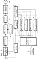
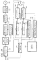
- FIG. 1 is a block diagram for describing an authoring apparatus in this embodiment.
- the authoring apparatus in this embodiment comprises a video signal input terminal 1, an electronic watermark information superimposition section (to be referred to as "WM superimposition section” hereinafter) 2, a timing control section 3, a PN generation section 4, a pattern switching section 5, a superimposition pattern determination section 6, a superimposition pattern generation section 7, a data compression processing section 8, a CGMS-D information addition section 9, a CGMS-D information generation section 10, an encoding section 11 and a record processing section 12.
- WM superimposition section electronic watermark information superimposition section
- a video signal to be recorded on a DVD 100 is supplied to the WM superimposition section 2 and the timing control section 3 through the input terminal 1.
- the WM superimposition section 2 is designed to, as will be described later, superimpose a spectrum spread signal for transmitting duplication control information in a preset superimposition/non-superimposition pattern on the video signal which has been inputted through the input terminal 1.
- the timing control section 3 comprises a synchronism detection circuit and a PLL circuit, and detects a vertical synchronizing timing signal V and a horizontal synchronizing timing signal H from the supplied video signal. Using the detected vertical synchronizing timing signal V and the horizontal synchronizing timing signal H as reference signals, the timing control section 3 generates various timing signals such as a PN code reset timing signal RE indicating timing at which the generation of a PN code starts (to be referred to as "reset signal RE” hereinafter), a PN generation enable signal EN indicating a block in which the PN code is generated (to be referred to as “enable signal EN” hereinafter), a block signal KS indicating a block in which the spectrum spread signal is superimposed and that in which the spectrum spread signal is not superimposed, i.e., a block (unit block) in which the spectrum spread signal is superimposed or not superimposed and a PN clock signal PNCLK.
- a PN code reset timing signal RE indicating timing at which the generation of a
- the reset signal is designed to generate a PN code string from its leading portion for each frame
- the enable signal EN is designed to turn the PN generation section 4 into a state in which a PN code can be generated (enable state) in any frame.
- the block signal KS is designed to set a block for each frame at a superimposition/non-superimposition block of a PN code string PS as a spectrum spread signal.
- the reset signal RE, the enable signal EN and PN clock signal PNCLK generated by the timing control section 3 are supplied to the PN generation section 4, and the block signal KS is supplied to the superimposition pattern generation section 7.
- the PN generation section 4 generates an M-series PN code string PS based on the enable signal EN, the PN clock signal PNCLK and the reset signal RE, comprises a plurality of stages of shift registers which are not shown and is constituted by several exclusive OR circuits which operate the appropriate tap output of the shift registers.
- the PN generation section 4 is turned into an enable state by the enable signal EN and generates a PN code by one chip for each clock of the clock signal PNCLK, thereby generating a PN code string PS having a preset code pattern reset in a one vertical cycle and supplying the PN code string PS to the pattern switching section 5.
- the PN code string PS thus obtained from the PN generation section 4 is used as a spectrum spread signal for transmitting duplication control information.
- the duplication control information is transmitted by the superimposition/non-superimposition pattern of the spectrum spread signal consisting of blocks in which the spectrum spread signal is superimposed and those in which the spectrum spread signal is not superimposed.
- the pattern switching section 5 is supplied with pattern information for determining the superimposition/non-superimposition pattern of the PN code string PS (to be referred to as "attribute pattern" hereinafter) from the superimposition pattern generation section 7. Then, based on the attribute pattern, the superimposition/non-superimposition of the PN code string PS1 is switched.
- attribute patterns corresponding to four duplication control states i.e., 1. None Copy, 2. Copy Once (one generation), 3. No More Copy and 4. Copy Free, respectively are preset.
- the attribute patterns corresponding to the above-stated four duplication control states are preset as follows.
- the attribute pattern indicating None Copy is "10011100", that indicating Copy Once is “11011000”, that indicating No More Copy is “11100111” and that indicating Copy Free is "11110011”.
- the superimposition pattern generation section 7 comprises a None Copy pattern register 71, a Copy Once pattern register 72, a No More Copy pattern register 73 and a Copy Free pattern register 74.
- Each of these pattern registers 71 to 74 holds eight-bit information corresponding to the above-stated preset attribute pattern in advance.
- Each of the pattern registers 71 to 74 of the superimposition pattern generation section 7 generates an attribute pattern in which one frame is a block (unit block) of the superimposition/non-superimposition of the PN code string PS and eight frames are a repetition cycle, based on the eight-bit information corresponding to the attribute pattern which the register itself holds and the block signal KS supplied from the timing control section 3.
- one duplication control state is expressed by an eight-frame superimposition/non-superimposition pattern formed by the superimposition/non-superimposition of the PN code string of each of the frames constituting consecutive eight frames.
- the block (unit block) of the superimposition/non-superimposition of the PN code string consists of one frame and the repetition cycle of an attribute pattern is an eight-frame cycle
- one-bit information is expressed by one frame (one unit frame) of the video signal
- one duplication control state is expressed by eight-bit information indicated by consecutive eight frames (eight unit blocks).
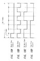
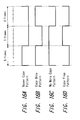
- FIG. 2 is a view for describing an example of attribute patterns generated in the registers 71 to 74 of the superimposition pattern generation section 7, respectively.
- Each of the pattern registers 71 to 74 of the superimposition pattern generation section 7 generates an attribute pattern based on the eight-bit information corresponding to the attribute pattern which the register holds itself and the block signal KS, as will be described hereinafter.
- the None Copy pattern register 71 generates an attribute pattern for indicating that the reproduction of a video signal is prohibited in which the first one unit block (one frame) is a high level, the next two unit blocks (two frames) are a low level, the next three unit blocks (three frames) are a high level and the last two unit blocks (two frames) are a low level, as shown in FIG. 2A.
- the No More Copy pattern register 72 generates an attribute pattern for indicating that the reproduction of a video signal is permitted once in which the first two unit blocks (two frames) are a high level, the next one unit block (one frame) is a low level, the next two unit blocks (two frames) are a high level and the last three unit blocks (three frames) are a low level, as shown in FIG. 2B.
- the No More Copy pattern register 73 generates an attribute pattern for indicating that the reproduction of a video signal is not permitted any more in which the first three unit blocks (three frame) are a high level, the next two unit blocks (two frames) are a low level and the last three unit blocks (three frames) are a low level, as shown in FIG. 2C.
- the Copy Free pattern register 74 generates an attribute pattern for indicating that the reproduction of a video signal is freely permitted in which the first four unit blocks (four frames) are a high level, the next two unit blocks (two frames) are a low level and the last two unit blocks (two frames) are a low level, as shown in FIG. 2D.
- the pattern registers 71 to 74 of the superimposition pattern generation section 7 can generate attribute patterns preset in accordance with duplication control information, as additional information superimposed on the video signal, for notifying duplication control states, respectively.
- the superimposition pattern determination section 6 controls an attribute pattern from which register among the four registers of the superimposition pattern generation section 7 is to be used.
- the superimposition pattern determination section 6 is controlled by a control section 20.
- the control section 20 which is a microcomputer comprising a CPU, a ROM, a RAM and the like, controls the respective sections of this authoring apparatus in accordance with indication input information inputted from the user of the authoring apparatus. Owing to this, if the duplication control state of a video signal to be recorded on the DVD 100 is indicated by the user of this authoring apparatus through, for example, a key operating section, which is not shown, of the authoring apparatus, then the control section 20 supplies a signal indicating that a register which generates an attribute pattern in accordance with the indication input from the user should be selected, to the superimposition pattern determination section 6.
- the superimposition determination section 6 selects a register which generates an attribute pattern for notifying a duplication control state in accordance with the user's indication based on the signal from the control section 20, and supplies a generation instruction signal instructing the selected register to generate the attribute pattern.
- the pattern register supplied with the generation instruction signal from the superimposition pattern determination section 6 among the four registers 71 to 74 of the superimposition pattern generation section 7 generates an attribute pattern with one unit block consisting of one frame and with a repetition cycle set at an eight-frame cycle based on the eight-bit information corresponding to the attribute pattern which the register holds itself and on the block signal KS from the timing control section 3, and supplies the generated attribute pattern to the pattern switching section 5.
- the pattern switching section 5 switches the superimposition/non-superimposition of the PN code string PS from the PN generation section 4 based on the supplied attribute pattern. Namely, the pattern switching section 5 outputs a PN code string in a unit block in which the attribute pattern from the superimposition pattern generation section 7 is a high level, and does not output a PN code string in a unit block in which the attribute pattern is a low level.
- the pattern switching section 5 supplies the PN code string PS from the PN generation section 4 to generate a superimposition block and non-superimposition block based on the attribute pattern from the superimposition generation section 7, to the WM superimposition section 2.
- the WM superimposition section 2 superimposes the PN code string PS switched to be superimposed or not superimposed, as a spectrum spread signal, to the video signal supplied through the input terminal 1.
- the pattern switching section 5 outputs a PN code string only in blocks in which the attribute pattern is a high level. Due to this, if the attribute pattern supplied to the pattern switching section 5 is one shown in FIG. 2A (Never Copy pattern) from the Never Copy pattern register 71, the PN code string PS is superimposed on the video signal in a superimposition/non-superimposition pattern indicated by a pattern Al in FIG. 2.
- the PN code string PS1 is superimposed on the video signal in a superimposition/non-superimposition pattern indicated by a pattern B1 in FIG. 2.
- the PN code string PS is superimposed on the video signal in a superimposition/non-superimposition pattern indicated by a pattern C1 in FIG. 2.
- the attribute pattern is one shown in FIG. 2D (Copy Free pattern) from the Copy Free pattern register, the PN code string PS1 is superimposed on the video signal in a superimposition/non-superimposition pattern indicated by a pattern D1 in FIG. 2.
- the superimposition level of the PN code string PS supplied to the WM superimposition section 2 is adjusted so as not to deteriorate the video signal on which the PN code string PS is superimposed.
- the superimposition level of the PN code string is adjusted such that the PN code string PS is superimposed at a lower level than that of the dynamic range of the video signal. Then, the video signal on which the PN code string PS as a spectrum spread signal is superimposed in a superimposition/non-superimposition pattern (attribute pattern) predetermined according to the selected duplication control state by the WM superimposition section 2, is supplied to the data compression processing section 8.
- the data compression processing section 8 conducts data compression of MPEG system to the video signal supplied thereto.
- the data-compressed video signal is supplied to the CGMS-D information addition section 9.
- CGMS-A information two-bit additional information for duplication control
- CGMS-D information two-bit additional information for duplication control
- the CGMS-D information addition section 9 adds the CGMS-D information supplied from the CGMS-D generation section 10 to the data-compressed digital video signal.
- the CGMS-D information generation section 10 generates CGMS-D information added to the video signal to be transmitted, based on the control signal from the control section 20.
- the CGMS-D information generated by the CGMS information generation section 10 signifies one of "Copy [00]", “Copy Once [10]” and "Never Copy [11]".
- the video signal to which the CGMS-D information is added by the CGMS-D information addition section 9 is supplied to the encoding section 11.
- the encoding section 11 conducts encoding processing of CSS (Contents Scramble System) system to the video signal.
- the encoding processing of the CSS system is a system conducted to an information signal if the information signal such as a video signal is recorded on and provided to a disk medium such as a DVD.
- the video signal which has been subjected to encoding processing by the encoding section 11 is supplied to the record processing section 12.
- the record processing section 12 conducts adjustment processing or the like to the supplied video signal so as to record the video signal on the DVD 100 and records the video signal on the DVD 100.
- the video signal on which the PN code string PS as a spectrum spread signal is superimposed so as to generate superimposition blocks and non-superimposition blocks is recorded on the DVD 100 and is supplied to the used with this DVD 100 as a transmission medium.
- the duplication control information notifying a duplication control state is transmitted by a superimposition/non-superimposition pattern in accordance with the attribute pattern of the PN code string PS superimposed on the video signal recorded on the disk 100.
- the video signal is not deteriorated. Further, the spectrum spread signal superimposed on the video signal is difficult to remove or manipulate. Due to this, it is possible to ensure supplying the spectrum spread signal together with the information signal such as a video signal to the recording apparatus or the reproducing apparatus, and it is possible for the apparatus supplied with the signal to detect the spectrum spread signal to thereby ensure, for example, duplication control or reproduction control.
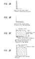
- FIG. 3 shows the relationship between the duplication control information superimposed as spectrum spread signals on the video signal and the video signal in the form of spectrums.
- the duplication control information indicates None Copy, Copy Once (One Generation), No More Copy or Copy Free as stated above.
- the information is small in amount and is a low-bit rate, narrow-bandwidth signal as shown in FIG. 3(a).
- the duplication control information is subjected to spectrum-spread, that is, the duplication control information is spectrum-spread using a PN code string generated in a sufficiently short cycle to thereby form a spectrum spread signal, or if the PN code string is used as a spectrum spread signal per se as stated above to indicate a duplication control state according to the superimposition/non-superimposition pattern of the PN code string, then the duplication control information turns into a signal in wide bandwidth as shown in FIG. 3(b). At this moment, the spectrum spread signal level becomes smaller in an inversely proportional manner to the increase rate of the bandwidth.
- the spectrum spread signal is superimposed on the video signal by the WM superimposition section 2.
- the spectrum spread signal is superimposed thereon at a lower level than that of the dynamic range of the video signal serving as an information signal. This makes it possible to hardly cause the deterioration of the main information signal. Therefore, as stated above, the video signal on which the spectrum spread signal is superimposed, is supplied to a monitor receiver. If the video signal is reproduced, a good reproduction picture can be obtained with less influence of the spectrum spread signal.
- the spectrum spread signal is reproduced as a signal in a narrow bandwidth as shown in FIG. 3(d).
- the power of the duplication control information after being de-spread exceeds that of the information signal and can be detected.
- the duplication control state is expressed according to the superimposition/non-superimposition pattern of the PN code string and the de-spread is conducted, then the portions on which the spectrum spread signals are superimposed have high level of the output obtained as a result of de-spread, so that the blocks in which the spectrum spread signals are superimposed on the video signal can be discriminated from those in which the spectrum spread signals are not superimposed thereon.
- the spectrum spread signals superimposed on the video signal are not removed and difficult to manipulate, so that it is possible to ensure transmitting the duplication control information and the further additional information together with the video signal.
- the authoring apparatus in this embodiment conducts spectrum spread using a PN code string in a one-frame cycle with a vertical synchronizing signal used as a reference signal, use of the vertical synchronizing signal as a reference signal allows a PN code string for de-spread to be generated for the video signal at the same timing as that of the spectrum spread and the spectrum spread signal can be, therefore, promptly extracted.
- the authoring apparatus in this embodiment employs a PN code string PS as a spectrum spread signal and notifies a duplication control state by a superimposition/non-superimposition pattern in accordance with the attribute pattern of the PN code string.
- attribute patterns for determining superimposition/non-superimposition patterns of the PN code string are preset in accordance with four duplication control states, respectively.
- a reproduction apparatus for reproducing the DVD on which the video signal is recorded by this authoring apparatus detects the superimposition/ non-superimposition pattern of the PN code string superimposed on the video signal and discriminates which duplication control state the superimposition/non-superimposition pattern corresponds to, whereby the reproduction apparatus can determine the duplication control state of the video signal is Never Copy, Copy Once, No More Copy or Copy Free.
- the duplication control information can be transmitted by the superimposition/non-superimposition pattern of the PN code string PS.
- the meaning of the information transmitted by the spectrum spread signal or, in this embodiment, duplication control information for notifying a duplication control state cannot be discriminated by simply detecting the spectrum spread signal superimposed on the video signal.
- the duplication control information on the video signal is transmitted by the superimposition/non-superimposition pattern of the PN code string PS superimposed on the video signal.
- the duplication control information on the video signal is to be removed or manipulated, it is required to do so per superimposition/non-superimposition pattern of the PN code string.
- FIG. 4 is a block diagram for describing a DVD reproduction apparatus for reproducing and outputting a video signal recorded on the DVD 100 from the DVD 100 created by the authoring apparatus described above with reference to FIG. 1.
- the reproduction apparatus in this embodiment comprises a readout section 21, a descramble section 22, a video data decoding section 23, a D/A converter circuit 24, a CGMS-A superimposition section 25, an analog vide signal output terminal 25a, a CGMS-D decoding section 26, a WM decoding section 27, an encoding section 28, an IEEE1394 interface 29, a digital video signal output terminal 29d, a control section 30 and a key operating section 31.
- the readout section 21 reads out the video signal from the DVD 100.
- the video signal read out by the readout section 21 is supplied to the descramble section 22 and descramble processing for descrambling the scramble of the video signal is conducted.
- the descrambled video signal is supplied to the video decoding section 23. Since the descrambled video signal is MPEG-compressed, the video signal is MPEG-decoded and expanded by the video data decoding section 23 so as to supply the video signal to, for example, a display monitor device.
- the MPEG-decoded video signal is supplied to the D/A converter circuit 24 and converted into an analog signal.
- the video signal converted into the analog signal is supplied to the CGMS-A superimposition section 25, where CGMS-A information is superimposed on a predetermined horizontal block in a vertical blanking period based on information from the control section 30.
- the control section 30, in this case, sets CGMS-A information superimposed on the outputted analog video signal based on CGMS-D information from the CGMS-D decoding section 26 to be described later and duplication control information from the WM decoding section 27 and supplies the CGMS-A information to the CGMS-A superimposition section 25 to thereby superimpose the CGMS-A information on the analog video signal.
- the analog video signal on which the CGMS-A information is superimposed in the CGMS-A superimposition section 25 is outputted, through the analog video signal output terminal 25a, to, for example, a display monitor device or a recording apparatus.
- the CGMS-A information and the duplication control information transmitted by the superimposition/non-superimposition pattern of the PN code string PS serving as a spectrum spread signal are superimposed on the video signal outputted through the analog video signal output terminal 25a.
- the MPEG-compressed video signal from the descramble section 22 can be outputted as a digital signal through an IEEE1394 standard interface bus.
- the IEEE1394 standard interface encodes the transmission digital information so as to prevent illegal duplication. Also, the interface verifies whether the output receiving side is a compliant apparatus and verifies the CGMS-D information and duplication control information from the WM decode 27 which are information for duplication control. In accordance with the verification results, it is determined whether or not a key for decoding the code is transmitted to the output receiving side.
- This communication control system stated above is referred to as an IEEE 1394 secure bus and the digital interface can effectively prevent duplication.
- the video signal outputted from the descramble section 22 is supplied to the CGMS-D decoding section 26 and CGMS-D information added to the video signal is extracted.
- the CGMS-D information is extracted as two-bit information at a specified position separated from video data in the CGMS-D information decoding section 26 and the two-bit information is supplied to the control section 30.
- the video signal which has been MPEG-decoded in the video data decoding section 23 is supplied to the electronic watermark information decoding section (to be referred to as "WM decoding section” hereinafter) 27, and the spectrum spread signal added to the video signal is extracted.
- WM decoding section electronic watermark information decoding section
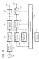
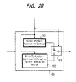
- FIG. 5 is a block diagram for describing the WM decoding section 27.
- the WM decoding section 27 comprises a timing control section 271, a PN generation section 272, a de-spread section 273, a superimposition pattern determination section 274 and a superimposition pattern generation section 275.
- the timing control section 271 of the WM decoding section 27 is constituted in the same manner as the timing control section 3 of the authoring apparatus described above with reference to FIG. 1 and comprises a synchronizing detection circuit and a PLL circuit.
- the MPEG-decoded video signal from the video decoding section 23 is supplied to both the de-spread section 273 and the timing control section as shown in FIG. 5.
- a vertical synchronizing timing signal V and a horizontal synchronizing timing signal H are detected from the supplied video signal. Then, using the detected vertical synchronizing timing signal V and the horizontal synchronizing timing signal H as reference signals, the timing control section 271 forms various PN clock signals such as a rest signal RE, an enable signal EN, a superimposition unit block signal KS indicating a superimposition unit block and a PN clock signal PNCLK.
- the timing control section 271 forms various timing signals for providing the same timing as that of the reset signal RE, the enable signal EN, the block signal KS and PN clock signal PNCLK, respectively, used in the above-stated authoring apparatus for the inputted video signal.
- the reset signal RE is a signal in a one-frame cycle and the enable signal EN is a signal for generating a de-spread PN code string in any frame for the video signal.
- the block signal KS is a signal in a one-frame cycle and the PN clock signal PNCLK is a signal for providing the same timing as that of the PN clock signal used by the authoring apparatus to generate a PN code string.
- the reset signal RE, the enable signal EN and PN clock signal PNCLK formed in the timing control section 271 are supplied to the PN generation section 272, whereas the block signal KS is supplied to the superimposition pattern generation section 275.
- the PN generation section 272 is constituted in the same manner as the PN generation section 4 of the above-stated authoring apparatus.
- the PN generation section 272 generates for the video signal based on the timing signal from the timing control section 271, a de-spread PN code string PS of the same series as that of the PN code string PS as a spectrum spread signal at the same timing as that at which the PN code string PS as a spectrum spread signal is superimposed on the video signal and supplies the de-spread PN code string PS to the de-spread section 273.
- the de-spread section 273 conducts de-spread using the de-spread PN code string PS from the PN generation section 272 and detects the spectrum spread signal superimposed on the video signal supplied to the de-spread section 273.
- the detection output from the de-spread section 273 is supplied to the superimposition pattern determination section 274.
- the PN code string PS as a spread code signal is superimposed on the video signal recorded on the DVD 100 in a superimposition/non-superimposition pattern in accordance with the preset attribute pattern to indicate the duplication control state of this video signal so as to generate superimposition blocks and non-superimposition blocks.
- the PN code string PS superimposed on the video signal in the authoring apparatus shown in FIG. 1 is generated as a de-spread PN code string for the video signal at the same timing as that during superimposition and de-spread is conducted using the generated PN code string PS, then de-spread detection output with respect to the blocks in which the PN code string PS is superimposed becomes a high level signal and that with respect to the blocks in which the PN code string is not superimposed becomes a low level signal.
- this de-spread section 272 it is possible to discriminate a block in which the PN code string PS is superimposed from a block in which the PN code string PS is not superimposed, and the superimposition/ non-superimposition pattern of the PN code string is detected in the superimposition pattern determination section 274.
- the superimposition pattern generation section 275 of this reproduction apparatus is provided with four pattern registers 751 to 754 for generating attribute patterns corresponding to the above-stated four duplication control states, respectively.
- each of the pattern registers 751 to 754 of the superimposition pattern generation section 275 generates an attribute pattern with one frame set as one block (unit block) of the superimposition/non-superimposition of the PN code string and with an eight-frame cycle set as a repetition cycle, based on the block signal KS.
- the pattern registers 751 to 754 of this superimposition pattern generation section 275 are constituted in the same manner as the pattern registers 71 to 74 of the superimposition pattern generation section 7 in the authoring apparatus described above with reference to FIG. 1, respectively.
- the None Copy pattern register 751 of this superimposition pattern generation section 275 generates an attribute pattern shown in FIG. 2A for indicating that the duplication of the video signal is prohibited and the Copy Once pattern register 752 generates an attribute pattern shown in FIG. 2B for indicating that the duplication of the video signal is permitted once.
- the No More Copy pattern register 763 generates an attribute pattern shown in FIG. 2C for indicating that the duplication of the video signal is not permitted any more and the Copy Free pattern register 274 generates an attribute pattern shown in FIG. 2D for indicating that the video signal can be freely duplicated.
- the attribute patterns generated by the respective pattern registers 751 to 754 of the superimposition pattern generation section 275 are simultaneously supplied to the superimposition pattern discrimination section 274.
- the superimposition pattern discrimination section 274 discriminates which attribute pattern the superimposition/non-superimposition pattern of the PN code string PS superimposed on the video signal corresponds, based on the detection output from the de-spread section 272 and the attribute patterns from the respective pattern registers 751 to 754 and supplies the determination result to the control section 30 of this video signal reproduction apparatus.
- the attribute pattern coincident with the superimposition/non-superimposition pattern of the PN code string PS1 indicates, for example, Never Copy, Copy Once, No More Copy and Copy Free
- information indicating the determination results of "11", "01", “10” and "00" are supplied to the control section 30, respectively.
- the information indicating these determination results are set according to the respective attribute patterns and managed by the superimposition pattern discrimination section 274.
- the superimposition pattern discrimination section 274 cannot determine an attribute pattern coincident with the superimposition/non-superimposition pattern of the PN code string superimposed on the video signal even after conducting pattern discrimination throughout eight frames (one repetition cycle) with the unit block of the superimposition/non-superimposition of the spectrum spread signal set at one frame, based on the block signal from the timing control section 271, the superimposition pattern discrimination section 274 notifies the timing control section 271 that an attribute pattern cannot be determined.
- the timing control section 271 shifts the repetition cycle block signal KS of the spectrum spread signal by one frame and shifts the leading frame of the repetition cycle of the spectrum spread signal, thereby synchronizing the repetition cycle of the superimposition/non-superimposition pattern of the PN code string with that of the superimposition/non-superimposition pattern of the PN code string PS formed and used by this video signal reproduction apparatus.
- the timing control section 271 can synchronize the PN code string PS superimposed on the video signal with the repetition cycle of the superimposition/non-superimposition pattern of the PN code string formed and used by this video signal reproduction apparatus based on the information from the superimposition pattern determination section 274.
- this video signal reproduction apparatus can obtain duplication control information transmitted by the superimposition/non-superimposition pattern of the PN code string PS. Also, as described above, the control section 30 is supplied with the CGMS-D information from the CGMS-D decoding section 26.
- control section 30 determines whether or not an encoding key for decoding the video signal encoded and outputted through the IEEE1394 interface 29 while taking account of the CGMS-D information from the CGMS-D decoding section 26 and the duplication control information from the WM decoding section 27.
- the output data of the descramble section 22 is also supplied to the encoding section 28, where the compressed video data is encoded based on different encoding keys according to communications under the control of the control section 30.
- the encoded data from the encoding section 28 is supplied to an electronic equipment to which the data is outputted through the IEEE1394 interface 29 and through the output terminal 29d.
- the IEEE1394 interface 29 converts the data so as to comply with the IEEE1394 interface standard and then outputs the data.
- control section 30 communicates with the equipment to which the data is outputted through the IEEE1394 interface 29, discriminates whether the equipment is a compliant apparatus and discriminates, if it is a compliant apparatus, whether or not the equipment is a recording apparatus.
- control section 30 determines whether or not encoding key information for decoding encoded data at the encoding section 28 is transmitted to the side to which the data is outputted, using the CGMS-D information from the CGMS-D decoding section 26, the duplication control information from the WM decoding section 27 and the discrimination information on the equipment to which the data is outputted through the IEEE1394 interface 29.
- the encoding key information is not fed to the apparatus. Even if the side to which the data is outputted is a compliant apparatus, the encoding key information is not fed to the apparatus when the apparatus is a recording apparatus and the CGMS information is [11] indicating "Never Copy” or the electronic watermark information indicates "Never Copy”.
- the reproduction apparatus in this embodiment reads out the video signal on which the spectrum spread signal is superimposed and also the CGMS information as another duplication control information is superimposed and which is recorded on the DVD 100, and conducts necessary processing such as descramble processing (decoding processing), expansion processing of the data-compressed digital video signal and output signal formation processing, thereby forming and outputting an analog video signal supplied to a monitor receiver and a digital video signal outputted through a digital interface.
- descramble processing decoding processing
- expansion processing of the data-compressed digital video signal and output signal formation processing thereby forming and outputting an analog video signal supplied to a monitor receiver and a digital video signal outputted through a digital interface.
- the digital video signal is outputted through the digital interface, it is ensured that illegal reproduction is prevented by the function of the digital interface IEEE1394 or based on the duplication control state indicated by the superimposition/non-superimposition pattern of the spectrum spread signal as well as CGMS information as described above.
- control section 30 appropriately determines CGMS information supplied to the CGMS-A superimposition section 25 based on the CGMS-D information from the CGMS-D decoding section 26 and the duplication control information from the WM decoding section 27, and supplies the CGMS information to the CGMS-A superimposition section 25.
- the side supplied with the analog video signal e.g., a recording apparatus such as a VTR can conduct duplication control using the CGMS-A information superimposed on the analog video signal and the duplication control information transmitted by the superimposition/ non-superimposition pattern of the spectrum spread signal.
- the video signal reproduction apparatus in this embodiment can detect duplication control information transmitted by the superimposition/non-superimposition pattern of the PN code string PS, as a spectrum spread signal, superimposed on the video signal and determine the duplication control state.
- FIG. 6 is a block diagram showing an example of the constitution of the compliant DVD recording apparatus supplied with the video signal reproduced by the video signal reproduction apparatus shown in FIG. 4 and recording the video signal on a DVD 200 as an RAM disk.
- this compliant recording apparatus comprises a digital input terminal 41d and an analog input terminal 44a for an IEEE1394 interface.
- the digital input terminal 41d is connected to an IEEE1394 interface 41.
- This IEEE1394 interface 41 conducts processing for recovering the data converted so as to comply with the IEEE1394 bus interface standard.
- the control section 60 can discriminate the type of equipment which supplies digital video data by communicating with the equipment through this IEEE1394 interface 41.
- Data from the IEEE1394 interface 41 is supplied to the decoding section 42.
- encoding key information for decoding the encoded data is fed from the equipment.
- the decoding section 42 can decode data from the IEEE1394, interface 41, when the encoding key information is obtained and recover the compressed video data.
- the compressed video data thus recovered is supplied to a selector 43.
- the video information inputted through the analog input terminal 44a is supplied to the compression encoding section 45 through the analog interface 44, MPEG-compressed and then supplied to the selector 43.
- the selector 43 selects and outputs either the data from the decoding section 42 or that from the encoding section 45 by a selector control signal in accordance with the selection input from the user inputted through the key operation section 51.
- the output data of this selector 43 is supplied to a record control section 48 through a CGMS-D rewrite section 48.
- the output data of the selector 43 is also supplied to a CGMS-D decoding section 46 and a WM decoding section 47.
- the CGMS-D decoding section 46 is constituted in the same manner as the CGMS-D decoding section 26 of the video signal reproduction apparatus described above with reference to FIG. 4. Further, the WM decoding section 47 is constituted almost in the same manner as the WM decoding section 27 provided in the above-described reproduction apparatus and described above with reference to FIG. 5. The WM decoding section 47 is also provided with MPEG decoding function.
- the WM decoding section 47 of the recording apparatus also has function of MPEG-decoding the supplied digital video signal which data is compressed by the MPEG system and can surely and accurately extract the electronic watermark information superimposed on the prior-to-compressed video signal.
- the CGMS-D decoding section 46 and the WM decoding section 47 extract and discriminate CGMS-D information and electronic watermark information as in the same manner as the CGMS-D decoding section 26 of the reproduction apparatus described above with reference to FIG. 4 and the WM decoding section 27 described above with reference to FIG. 5 and the discrimination outputs of the CGMS-D information and the electronic watermark information are supplied to the control section 60.
- the CGMS-D information is extracted as two-bit information at a specified position separated from the video data and the two-bit information is supplied to the control section 60.
- the WM decoding section 47 has function of MPEG-decoding the video signal from the selector 43 as stated above and is also constituted in the same manner as the WM decode 27 shown in FIG. 5. Description will now be given while assuming that the WM decode 47 is constituted as shown in FIG. 5.
- the WM decoding section 47 MPEG-decodes the video signal from the selector 43 and the video signal which has been MPEG-decoded is supplied to the timing control section 271 and the de-spread section 273.
- the timing control section 271 detects a vertical synchronizing timing signal V and a horizontal synchronizing timing signal H from the supplied video signal as already stated above. Using these signals as reference signals, the timing control section 271 forms various types of timing signals such as a reset signal RE, an enable signal EN, a superimposition unit block signal KS indicating a superimposition unit block and a PN clock signal PNCLK.
- timing signals are intended to provide the video signal supplied to this WM decoding section 47 with the same timing as that of the respective timing signals used when the PN code string PS is formed as a spectrum spread signal and superimposed on the video signal in the authoring apparatus shown in FIG. 1.
- the PN generation section 272 generates, for the video signal, a PN code string PS having the same series as that of the PN code string PS superimposed, as a spectrum spread signal, on the video signal using the reset signal RE, the enable signal EN and the PN clock PNCLK from this timing control section 47, and supplies the PN code string PS to the de-spread section 273.
- the de-spread section 273 conducts de-spread using the PN code string PS from the PN generation section 272 and supplies the detection output to the superimposition pattern determination section 274.
- This superimposition pattern determination section 274 is supplied with four types of attribute patterns formed by the respective pattern registers 751 to 754 of the superimposition pattern generation section 275 as stated above with reference to FIG. 2.
- the superimposition pattern determination section 274 discriminates which attribute pattern the superimposition/non-superimposition pattern of the spectrum spread signal superimposed on the supplied video signal corresponds to, based on the detection output from the de-spread section 272 and the four types of attribute patterns from the superimposition pattern generation section 275, and supplies the discrimination result to the control section 50.
- the superimposition pattern determination section 274 supplies, to the control section 60, information (duplication control information) indicating a determination result of "11" when an attribute pattern coincident with the superimposition/non-superimposition pattern of the PN code string PS1 shows None Copy, that of "01” when Copy Once, that of "10” when an attribute pattern coincident with the superimposition/non-superimposition pattern of the PN code string PS1 shows No More Copy and "00" when an attribute pattern coincident with the superimposition/non-superimposition pattern of the PN code string PS1 shows Copy Free.
- the control section 60 discriminates whether or not input information can be recorded (duplicated) based on the CGMS-D information from the CGMS-D decode 46 and the duplication control information from the WM decoding section 47, and, if discriminating that it can be recorded (duplicated), discriminates whether the CGMS-D information for duplication control needs to be rewritten.
- control section 60 controls the record control section 49 such that recording is not executed.
- control section 60 controls the record control section 49 such that recording is executed and the recorded data is subjected to specific scramble from the scramble section 50 to be recorded on the DVD 200. If discriminating that the input information can be duplicated once, the control section 60 causes the CGMS-D rewrite section 48 to execute the rewriting of the CGMS-D information.
- the CGMS rewrite section 48 in this case may be constituted such that two-bit data is extracted to rewrite a state [10] to a state [11] since the CGMS information is the two-bit data at a specific position in the data stream from the decoding section 42.
- the duplication control information transmitted by the superimposition/non-superimposition pattern of the PN code string PS is not rewritten. This is because the generation of the video signal can be limited based on information indicating a medium type recorded on the DVD as a recording medium and duplication control information as follows.
- the recording apparatus reads out the medium type of the DVD on which the video signal is recorded. If this medium type is a writable RAM disk and duplication control information indicates Copy Once, it is possible to discriminate that the vide signal on which the duplication control information indicating Copy Once is superimposed and which is recorded on the RAM disk has been duplicated (copied) on the RAM disk. In that case, the recording apparatus sets that duplication is not permitted any more.
- the duplication control information transmitted by the superimposition/non-superimposition pattern of the PN code string PS can be rewritten.
- the superimposition/non-superimposition pattern of the PN code string PS which has already been superimposed on the video signal is removed, the superimposition/non-superimposition pattern of the PN code string PS indicating No More Copy may be superimposed on the video signal.
- a so-called compliant recording apparatus can detect the superimposition/non-superimposition pattern of a spectrum spread signal superimposed on a supplied video signal, discriminate duplication control information corresponding to the superimposition/non-superimposition pattern and ensure conducting duplication control.
- the duplication control transmitted by the superimposition/non-superimposition pattern of the spectrum spread signal may be preferentially used in view of high reliability to thereby control the record control section 49.
- the duplication control information transmitted by the superimposition/non-superimposition pattern of the PN code string PS is superimposed on the video signal supplied to the DVD recording apparatus from the DVD reproduction apparatus.
- it is impossible to discriminate the meaning of the duplication control information transmitted by means of the spectrum spread signal by simply detecting the spectrum spread signal superimposed on the video signal.
- the duplication control information superimposed on the video signal is represented by the superimposition/non-superimposition pattern of the PN code string PS, it is possible to transmit the duplication control information while making higher the concealment characteristics of the duplication control information and make it more difficult to remove or manipulate the duplication control information on the video signal.
- the DVD recording apparatus can surely discriminate the duplication control information superimposed on the supplied video signal and appropriately conduct duplication control over the video signal.
- duplication control information is transmitted by the superimposition/non-superimposition pattern of a spectrum spread signal. It is, however, possible to transmit information by the reversal/non-reversal of the spectrum spread signal between a block in which the spectrum spread signal is superimposed as it is and that in which the spectrum spread signal is superimposed with its phase reversed instead of transmitting the information by the superimposition/non-superimposition pattern of the spectrum spread signal.
- PN code string PS which is a spectrum spread signal is superimposed on a video signal as it is in high level blocks of the attribute patterns and the PN code string PS is superimposed thereon with its phase reversed in low level blocks thereof.
- an attribute pattern is expressed by the reversal/non-reversal pattern of the spectrum spread signal and duplication control information can be transmitted by the reversal/ non-reversal pattern of this spectrum spread signal.
- the PN code string PS is superimposed on the video signal in the reversal/non-reversal pattern indicated by the pattern A2 of FIG. 2.
- an attribute pattern is the Copy Once pattern shown in FIG. 2B
- the PN code string PS is superimposed on the video signal in the reversal/non-reversal pattern indicated by the pattern B2 of FIG. 2.
- the PN code string PS is superimposed on the video signal in the reversal/non-reversal pattern indicated by the pattern C2 of FIG. 2.
- the PN code string PS is superimposed on the video signal in the reversal/non-reversal pattern indicated by the pattern D2 of FIG. 2.
- the pattern switching section 5 of the authoring apparatus described above with reference to FIG. 1 may control the reversal/ non-reversal of the spectrum spread signal based on the attribute pattern from the superimposition pattern generation section.
- the detection output from the de-spread section 272 of the WM decoding section 27 is positive (+) in non-reversal blocks and negative (-) in reversal blocks.
- a block of the superimposition/non-superimposition of a spectrum spread signal and that of the reversal/non-reversal thereof consist of one frame, respectively and duplication control information is transmitted by the superimposition/non-superimposition pattern or reversal/non-reversal pattern in an eight-frame cycle.
- the present invention should not be, however, limited thereto.
- the length of a superimposition/non-superimposition block or reversal/non-reversal block that is, a unit block can be set larger than that in the preceding embodiment, such as two frames, three frames,.... In this way, by setting the length of the unit block large, it is possible to intensify the strength of the spectrum spread signal superimposed on the video signal against, for example, filtering or various attempts.
- the length of the unit block can be set smaller than that in the embodiment stated above, such as 1/2 frame, 1/3 frame. It goes without saying that a superimposition/non-superimposition block or reversal/non-reversal block may be set using a horizontal synchronizing signal instead of a vertical synchronizing signal.
- the repetition cycle of the superimposition/non-superimposition pattern or reversal/non-reversal pattern should not be limited to an eight-frame cycle and can be longer or shorter than that in the embodiment described above.
- the superimposition/non-superimposition pattern or reversal/non-reversal pattern should not be limited to the above-stated embodiment and various patterns can be used. In that case, a pattern which does not cause erroneous detection even if detection synchronism is shifted during the detection of the superimposition/non-superimposition pattern or reversal/non-reversal pattern, should be used.
- duplication control information is superimposed on a video signal using a spectrum spread signal.
- the information signal should not be limited to the video signal. It is possible to superimpose duplication control signal as a spectrum spread signal on an information signal such as a voice signal.
- a superimposition/non-superimposition block (unit block) or a reversal/non-reversal block (unit block) may be set according to the preset data amount or time length of the information signal such as a voice signal.
- an information signal is, for example, a digital signal
- a superimposition/non-superimposition block or reversal/non-reversal block may be set based on preset unitary data such as a block for processing the digital information or based on time length, such as one block for 0.5 second or one block for one second.
- a video synchronizing signal cannot be employed as a reference signal.
- preset start information and end information on a spectrum spread signal are contained in the superimposition/non-superimposition pattern or reversal/non-reversal pattern superimposed on an information signal such as a voice signal or a synchronizing signal for detecting a superimposition/non-superimposition pattern or reversal/non-reversal pattern is superimposed as a spectrum spread signal.
- FIGS. 7 and 8 are views for describing a case where the superimposition/non-superimposition pattern or reversal/non-reversal pattern of a spectrum spread signal for transmitting additional information such as duplication control information is superimposed on an information signal such as a voice signal.
- preset start information and end information as a spectrum spread signal is contained in the superimposition/non-superimposition pattern or reversal/non-reversal pattern of a spectrum spread signal for transmitting additional information, and the respective blocks of the superimposition/non-superimposition pattern or reversal/non-reversal pattern are synchronized with one another using the start information and end information.
- the start bit (start information) and the end bit (end information) are information of the forefront and last blocks, respectively, within a plurality of blocks constituting the superimposition/non-superimposition or reversal/non-reversal pattern.
- the preset start bit When the preset start bit is detected, it is judged that the superimposition/non-superimposition pattern or reversal/non-reversal pattern of the spectrum spread signal is superimposed and the superimposition/non-superimposition or reversal/non-reversal of the spectrum spread signal for every unit block until the preset end bit is detected, is detected, whereby the superimposition/non-superimposition pattern or reversal/non-reversal pattern can be detected.
- a spectrum spread signal forming the start bit and the end bit and that superimposed on the respective unit blocks put between the start and end bits can be formed by using the same series of PN code strings.
- a spectrum spread signal for generating a synchronizing pulse is added to the superimposition/non-superimposition pattern or reversal/non-reversal pattern. That is, as shown in FIG. 8A, a spectrum spread signal as a synchronizing signal (which is described as synchronizing WM in FIG. 8B) is added in front of the superimposition/non-superimposition pattern or reversal/non-reversal pattern.
- the synchronizing WM and the superimposition/non-superimposition pattern or reversal/non-reversal pattern can be formed by using the same series of PN code strings.
- the synchronizing WM and the superimposition/non-superimposition pattern or reversal/non-reversal pattern by using PN code strings of different series.
- the superimposition/non-superimposition pattern or reversal/non-reversal pattern is formed using a PN code string PS1
- the synchronizing WM is formed using a PN code string PS2.
- the synchronizing WM and the superimposition/non-superimposition pattern or reversal/non-reversal pattern are transmitted by spectrum spread signals formed by different PN code strings, respectively, they can be surely detected even if they are superposed on each other in the same time range.
- the synchronizing WM is provided just before the superimposition/non-superimposition pattern or reversal/non-reversal pattern.
- the present invention should not be, however, limited thereto.
- the synchronizing WM may be provided between one superimposition/non-superimposition pattern and another superimposition/non-superimposition pattern or provided between one reversal/non-reversal pattern and another reversal/non-reversal pattern.
- the synchronizing WM and the superimposition/non-superimposition pattern or reversal/non-reversal pattern may not be necessarily adjacent each other.
- the synchronizing WM may be added so that both the synchronizing WM and the superimposition/non-superimposition or reversal/non-reversal pattern can be detected.
- the superimposition/non-superimposition patterns or reversal/non-reversal patterns for transmitting a plurality of additional information are formed using the same series of PN code strings PS.
- the present invention should not be, however, limited thereto.
- PN code strings serving as spectrum spread signals while using the same pattern or to transmit more types of additional information by a plurality of different PN code strings and superimposition/non-superimposition patterns or reversal/non-reversal patterns.
- the attribute patterns registered in the memory of the control section 20 in advance are supplied to the pattern switching section 5 and the superimposition/non-superimposition pattern or reversal/non-reversal pattern of the PN code string from the PN generation section 4 is switched based on information corresponding to the attribute pattern from this control section 20 without providing the superimposition pattern determination section 6 and the superimposition pattern generation section 7.
- the block signal KS among the timing signals formed by the timing control section 3 may be supplied to the pattern switching section 5, the pattern switching section 5 may use the timing signal from the timing control section 3 and switch the superimposition/non-superimposition pattern or reversal/non-reversal pattern of the PN code string serving as a spectrum spread signal based on the information corresponding to the attribute pattern from the control section 20.
- information corresponding to an attribute pattern from the control section 30, 60 and the block signal from the timing control section 271 are supplied to the superimposition pattern determination section 274 and the superimposition/non-superimposition pattern or reversal/non-reversal pattern of the PN code string serving as a spectrum spread signal superimposed on a to-be-processed video signal can be discriminated based on the information.
- attribute patterns should not be limited to those described above. Attribute pattern can be set according to, for example, M series codes.
- the repetition cycle of an attribute pattern, superimposition/non-superimposition blocks, reversal/non-reversal blocks and the like should not be limited to those in the above-stated embodiments. If an information signal is, for example, a video signal, the cycle and length synchronous with a video synchronizing signal may suffice.
- the information signal output apparatus is applied to an authoring apparatus
- the information signal processing apparatus is applied to a video signal reproduction apparatus (DVD reproduction apparatus)
- the information signal recording apparatus is applied to a DVD recording apparatus.
- the present invention should not be, however, limited thereto.
- the information signal output apparatus can be applied to a broadcasting apparatus for transmitting a broadcast signal from a broadcasting station, an information signal recording apparatus and an information signal recording and reproduction apparatus such as a so-called recording and reproduction apparatus for a DVD used in household or a VTR (video tape recorder), as well as an information processing apparatus provided with communication function of transmitting and receiving information through communication media such as internet.
- the information signal output apparatus can be applied to various types of apparatuses for outputting various information signals such as a video signal, a voice signal and communication data.
- the information signal processing apparatus can be applied to, for example, a receiver referred to as a set-top box for receiving digital broadcasting and supplying it to a monitor receiver or a recording apparatus and to an information processing apparatus provided with communication function of transmitting and receiving information through communication media such as internet.
- the present invention can be applied to various types of processing apparatuses supplied with various information signals such as a video signal, a voice signal and communication data and processing them.
- the information signal recording apparatus can be applied to, for example, a VTR (video tape recorder), a small-sized magneto-optical disk recording apparatus and recording and reproduction apparatus referred to as (a mini-disk), a hard disk device or a computer recording an information signal on a hard disk device or the like.
- a VTR video tape recorder
- a mini-disk small-sized magneto-optical disk recording apparatus and recording and reproduction apparatus referred to as (a mini-disk)
- a hard disk device or a computer recording an information signal on a hard disk device or the like Namely, if an information signal is recorded on various types of recording media such as a magnetic tape, a magnetic disk, an optical disk, a magneto-optical disk and a semiconductor memory, the information signal recording apparatus according to the present invention can be applied to various types of recording apparatuses for conducting duplication control using duplication control information superimposed on the information signal.
- a PN code is used as a spread code for forming a spectrum spread signal.
- the spread code should not be, however, limited thereto.
- Various types of spread codes can be used as a spread code for forming a spectrum spread signal.
- a spectrum spread signal is used as electronic watermark information.
- the electronic watermark information should not be, however, limited to the spectrum spread signal.
- Various types of electronic watermark information formed by means of the electronic watermark technique can be superimposed on an information signal in a superimposition/non-superimposition pattern or reversal/non-reversal pattern.
- a video signal on which electronic watermark information is superimposed is a digital signal
- the electronic watermark information is superimposed on a digital signal which is not MPEG-encoded yet. It is of course possible to superimpose the electronic watermark information on a digital video signal which has been MPEG-encoded.
- information notified by the superimposition/non-superimposition pattern or reversal/non-reversal pattern of electronic watermark information should not be limited to duplication control information.
- additional information such as copyright information can be transmitted by the superimposition/non-superimposition pattern or reversal/non-reversal pattern of electronic watermark information.
- FIG. 9 is a block diagram for describing a video signal recording apparatus in the second embodiment.
- the video signal recording apparatus in the second embodiment is designed to superimpose a spectrum spread signal for transmitting duplication control information and a spectrum spread signal for transmitting further additional information on a video signal at the same time with the same frequency with respect to the video signal and then to transmit them.
- the video signal recording apparatus in the second embodiment comprises a video signal input terminal 101, an electronic watermark information superimposition section (to be referred to as "WM superimposition section” hereinafter) 102, a timing control section 103, the first PN generation section 104, the second PN generation section 105, a duplication control information pattern generation section 106, a further additional information pattern generation section 107, the first pattern switching section 108, the second pattern switching section 109, a data compression processing section 110, a CGMS information addition section 111, a CGMS information generation section 112, an encoding section 113, a record processing section 114 and a control section 115.
- WM superimposition section electronic watermark information superimposition section
- a video signal to be recorded on a DVD 100 is supplied to the WM superimposition section 102 and the timing control section 103 through the input terminal 101.
- the WM superimposition section 102 is designed to, as will be described later, superimpose a spectrum spread signal for transmitting duplication control information and a spectrum spread signal for transmitting further additional information such as copyright information on the video signal which has been inputted through the input terminal 101.
- the timing control section 103 comprises a synchronism detection circuit and a PLL circuit, and detects a vertical synchronizing timing signal V and a horizontal synchronizing timing signal H from the supplied video signal. Using the detected vertical synchronizing timing signal V and the horizontal synchronizing timing signal H as reference signals, the timing control section 3 generates a PN code reset timing signal RE indicating timing at which the generation of a PN code starts (to be referred to as "reset signal RE"), a PN generation enable signal EN indicating a block in which the PN code is generated (to be referred to as "enable signal EN”), a signal indicating a block in which the spectrum spread signals are superimposed and that in which the spectrum spread signals are not superimposed, i.e., a block signal KS indicating a unit block in which the spectrum spread signals are superimposed/non-superimposed, and various timing signals such as a PN clock signal PNCLK.
- RE a PN code reset timing signal RE indicating timing at which the generation of
- the reset signal RE, the enable signal EN and the PN clock signal PNCLK generated by the timing control section 103 are supplied to the PN generation section 104 and the PN generation section 105, and the block signal KS is supplied to the duplication control information pattern generation section 106 and the further additional information pattern generation section 107.
- Each of the first PN generation section 104 and the second PN generation section 105 generates a PN code string used as a spread code based on the enable signal EN, the PN clock signal PNCLK and the reset signal RE, comprises a plurality of stages of shift registers which are not shown and is constituted by several exclusive OR circuits which operate the appropriate tap output of the shift registers.
- Each of the first PN generation section 104 and the second PN generation section 105 is reset by the reset signal RE in an N-frame cycle and generates a PN code string PS having a preset code pattern from its leading portion.
- the enable signal EN turns the first PN generation section 104 and the second PN generation section 105 into an enable state in any frame.
- the first PN generation section 104 and the second generation section 105 generate PN code strings of different series.
- the first PN generation section 104 generates a PN code string PS1 and the second PN generation section 105 generates a PN code string PS2.
- the first PN generation section 104 and the second PN generation section 105 are turned into a state in which respective PN codes can be generated (in an enable state) by the enable signal EN.
- the first PN generation section 104 and the second PN generation section 105 generate the PN code strings PS1 and PS2 having preset code patterns to be reset in an N-frame cycle or, in the second embodiment, in a five-frame cycle, respectively.
- the PN code string PS1 generated by the first PN generation section 104 is used as a spectrum spread signal for transmitting duplication control information and supplied to the first pattern switching section 108.
- the PN code string PS2 generated by the second PN generation section 105 is used as a spectrum spread signal for transmitting further additional information and supplied to the second pattern switching section 109.
- the duplication control information is transmitted by the superimposition/non-superimposition pattern of the spectrum spread signal consisting of blocks in which the spectrum spread signal is superimposed and those in which the spectrum spread signal is not superimposed.
- the further additional information of a plurality of bits is transmitted such that blocks in which the spectrum spread signal is superimposed and blocks in which the spectrum spread signal is not superimposed indicate one-bit information, respectively such as, for example, the former block indicates "1" and the latter block indicates "0".
- the first pattern switching section 108 is supplied with pattern information (to be referred to as "attribute pattern" hereinafter in this specification) for determining the superimposition/non-superimposition pattern of the PN code string PS1 from the duplication control information pattern generation section 106.
- the second pattern switching section 109 is supplied with an indication signal indicating the superimposition/non-superimposition of the PN code string PS2 from the further additional information pattern generation section 107.
- the duplication control information pattern generation section 106 generates an attribute pattern for determining the superimposition/non-superimposition pattern of the PN code string PS1 from the first PN generation section 104 based on information from the control section 115 and the block signal KS from the timing control section 103.
- information indicating in which attribute pattern the PN code string PS1 is superimposed on the video signal among attribute patterns corresponding to four duplication control states i.e., 1. None copy; 2. Copy once (one generation); 3. No More Copy; and 4. Copy Free, respectively, that is, information for indicating an attribute pattern to determine the superimposition/non-superimposition pattern of the PN code string 101 is supplied from the control section 115 to the duplication control information pattern generation section 106.
- the attribute patterns corresponding to the above-stated four duplication control states are preset as follows. Namely, in the second embodiment, the attribute pattern indicating No Copy is "10000000", that indicating Copy Once is “10101010”, that indicating No More Copy is "11001100” and that indicating Copy Free is "11110000”.
- the control section 115 supplies eight-bit information corresponding to the above-stated attribute pattern as information indicating the attribute pattern to the duplication control information pattern generation section 106.
- which of the information indicating an attribute pattern among those attribute patterns is supplied to the duplication control information pattern generation section 106 depends on, for example, the copyright owner of a video signal recorded on the DVD. That is to say, the copyright owner of the video signal recorded on the DVD determines which duplication control information is to be superimposed on the video signal.
- the user (operator) of the video signal recording apparatus in the second embodiment executes the recording of the video signal on the DVD
- information indicating duplication control information to be superimposed on the video signal recorded on the DVD is inputted through a key operating section, which is not shown, in the video signal recording apparatus.
- the eight-bit information indicating an attribute pattern in accordance with this inputted indication information is supplied from the control section 115 to the duplication control information pattern generation section 106.
- the duplication control information pattern generation section 106 generates an attribute pattern for determining the superimposition/non-superimposition pattern of the PN code string 101, that is, determining that the unit block for controlling the superimposition/non-superimposition of the PN code string PS1 (block in which the spectrum spread signal is superimposed or not superimposed) consists of five frames and that the repetition cycle consists of 40 frames, based on the information indicating the attribute pattern from the control section 115 and the block signal KS from the timing control section 103.
- FIG. 10 is a view for describing attribute patterns generated by the duplication control information pattern generation section 106.
- the duplication control information pattern generation section 106 When the information indicating an attribute pattern from the control section 115 is "10000000" indicating None Copy, the duplication control information pattern generation section 106 generates the attribute pattern in a 40-frame cycle in which the first block (five frames) constituting the attribute pattern is high level and the following seven blocks (35 frames) thereof are low level as shown in FIG. 10A.
- the duplication control information generation section 106 When information indicating an attribute pattern from the control section 115 is "10101010" indicating Copy
- the duplication control information generation section 106 generates the attribute pattern in a 40-frame cycle in which high and low levels are repeated for every block (five frames), that is, the first block (five frames) constituting the attribute pattern is high level and the second block (five frames) is low level as shown in FIG. 10B.
- the duplication control information generation section 106 when information indicating an attribute pattern from the control section 115 is "11001100" indicating No More Copy, the duplication control information generation section 106 generates the attribute pattern in a 40-frame cycle in which the high level and the low level are repeated for every two blocks (ten frames), that is, the first two blocks (ten frames) constituting the attribute pattern are high level and the next two blocks (ten frames) thereof are low level as shown in FIG. 10C.
- the duplication control information pattern generation section 106 when information indicating an attribute pattern from the control section is "11110000" indicating None Copy, the duplication control information pattern generation section 106 generates the attribute pattern in a 40-frame cycle in which the first four blocks (20 frames) constituting the attribute pattern are high level and the next four blocks (20 frames) thereof are low level as shown in FIG. 10D.
- the first pattern switching section 108 outputs the PN code string PS1 in blocks in which this attribute pattern is high level and does not output the PN code string PS1 in blocks in which the attribute pattern is low level, based on the attribute pattern from the duplication control information pattern generation section 106. In this way, the PN code string PS1 controlled to be superimposed or not superimposed in accordance with the attribute pattern from the duplication control information pattern generation section 106 is supplied to the WM superimposition section 102.
- the reason for setting the attribute pattern at a pattern in an eight-frame cycle having five frames per block is that further additional information to be described later is eight-bit information and that the data length of the superimposition/non-superimposition pattern for transmitting duplication control information is matched to that of further additional information so as to superimpose the duplication control information and the further additional information on the video signal at the same time with the same frequency.
- the further additional information pattern generation section 107 generates an indication signal indicating the superimposition/non-superimposition of the PN code string 102, that is, indicating that the unit block for controlling the superimposition/non-superimposition of the PN code string PS2 (block at electronic watermark information is superimposed or not superimposed) consists of five frames and that the superimposition cycle consists of 40 frames, based on the further additional information from the control section 115 and the block signal KS from the timing control section 103 as in the case of the duplication control information pattern generation section 106 stated above.
- the further additional information mentioned herein is information inputted through the key operating section, which is not shown, in the video signal recording apparatus when the user (operator) of the video signal recording apparatus in the second embodiment executes the recording of the video signal on the DVD.
- further additional information of eight bits such as "11100110” is supplied from the control section 115 to the further additional information pattern generation section 107.
- the further additional information pattern generation section 107 expresses each bit of further additional information by one block (five frames) and forms an indication signal indicating that one block (five frames) corresponding to bit "1" of the further additional information is high level and that one block (five frames) corresponding to bit "0" is low level.
- the further additional information pattern generation section 107 forms an indication signal indicating that the first three blocks (15 frames) are high level, the next two blocks (ten frame) are low level, the next two blocks (ten frames) are high level and the last block (five frames) is low level, and supplies the indication signal to the second pattern switching section 109.
- the second pattern switching section 109 outputs the PN code string PS2 in blocks in which the indication signal is high level and does not output the PN code string PS2 in blocks in which the indication signal is low level, based on the indication signal from the further information pattern generation section 107 as in the case of the above-stated first pattern switching section 108.
- the PN code string PS2 controlled to be superimposed or not superimposed is supplied to the WM superimposition section 102 in accordance with the indication signal from the further additional information pattern generation section 107.
- the WM superimposition section 102 is supplied with the spectrum spread signals controlled to be superimposed or not superimposed from the first pattern switching section 108 and the second pattern switching section 109 and superimposes the spectrum spread signals on the video signal supplied through the input terminal 101.
- the PN code strings PS1 and PS2 controlled to be superimposed or not superimposed are superimposed on the video signal so as to be superposed on each other at the same time with the same frequency.
- FIG. 11 is a view for describing the duplication control information and the further additional information superimposed on the video signal in the second embodiment.
- one block of the duplication control information consists of five frames and the duplication control information is transmitted by the superimposition/non-superimposition pattern of the PN code string PS1 of a 40-frame cycle (eight blocks).
- One block of the further additional information consists of five frames and the further additional information is transmitted depending on the superimposition/non-superimposition of the PN code string PS2 in each block in the 40-frame cycle (eight blocks).
- the PN code strings PS1 and PS2 are spectrum spread signals and superimposed on the video signal with the same frequency as that of the video signal.
- Each of the PN code strings PS1 and PS2 is, however, formed by using different series of PN code strings as stated above. Due to this, by conducting de-spread using the PN code strings PS1 and PS2, it is possible to ensure detecting each of the PN code strings PS1 and PS2 superimposed on the video signal at the same time with the same frequency.
- each of the PN code strings PS1 and PS2 supplied to the WM superimposition section 102 is adjusted so as not to deteriorate the video signal on which they are superimposed.
- each of the PN code strings PS1 and PS2 is superimposed at a lower level than that of the dynamic range of the video signal.
- the video signal on which the PN code string PS1, for transmitting duplication control information, controlled to be superimposed or not superimposed and the PN code string PS2 for transmitting further additional information are superimposed by the WM superimposition section 102 is supplied to the data compression processing section 110.
- the data compression processing section 110 compresses the vide signal supplied thereto to the MPEG system.
- the data compressed video signal is supplied to the CGMS (Copy Generation Management System) information addition section 111 so as to add the duplication control information of the CGMS to the data compressed video signal.
- CGMS Copy Generation Management System
- CGMS information two-bit additional information for duplication control
- the CGMS information addition section 111 adds the CGMS information supplied from the CGMS generation section 112 to the data compressed digital video signal.
- the CGMS information generation section 112 generates CGMS information added to the video signal to be transmitted, based on the control signal from the control section 115.
- the CGMS information generated by the CGMS information generation section 112 signifies one of "Copy [00]", “Copy Once [10]” and "Never Copy [11]".
- the video signal to which the CGMS information is added by the CGMS information addition section 111 is supplied to the encoding section 113.
- the encoding section 113 conducts encoding processing of CSS (Contents Scramble System) to the video signal.
- the encoding processing of the CSS system is a system conducted to an information signal if the information signal such as a video signal is recorded on and provided to a disk medium such as a DVD.
- the video signal which has been subjected to encoding processing by the encoding section 113 is supplied to the recording processing section 114.
- the recording processing section 114 forms a video signal to be recorded on the DVD 100 from the supplied video signal and records the formed video signal on the DVD 100.
- the video signal on which the duplication control information transmitted according to the superimposition/non-superimposition pattern of the PN code string PS1 and the further additional information consisting of eight-bit information so that one-bit information is expressed by the superimposition/non-superimposition block of the PN code string PS2 are superimposed is recorded on the DVD 100 and the video signal is provided to the user with the DVD 100 used as a transmission medium.
- the video signal is not deteriorated. Further, the spectrum spread signals superimposed on the video signal are difficult to remove or manipulate. Due to this, it is possible to ensure supplying the spectrum spread signals together with the information signal such as a video signal to the recording apparatus or the reproducing apparatus, and it is possible for the apparatus supplied with the signals to detect the spectrum spread signals to thereby ensure, for example, duplication control or reproduction control.
- the video signal recording apparatus in this embodiment transmits the duplication control information by the superimposition/non-superimposition pattern of the spectrum spread signal and transmits the further additional information depending on the superimposition/non-superimposition of the spectrum spread signal for each preset block.
- FIG. 12 is a block diagram for describing a video signal reproduction apparatus in the second embodiment for reproducing and outputting a video signal from a DVD 100 on which the video signal is recorded by the video signal recording apparatus described with reference to FIG. 9.
- the superimposition/non-superimposition pattern of the PN code string PS1 for transmitting the duplication control information and a block group in which the superimposition/non-superimposition of the PN code string PS2 for transmitting further additional information is controlled are superimposed on the video signal at the same time with the same frequency.
- PN code strings PS1 and PS2 are generated at the same timing in which the PN code strings PS1 and PS2 are superimposed on the video signal, and de-spread is conducted using them as spread codes for de-spread, whereby it is possible to detect the PN code strings PS1 and PS2 and then to detect the superimposition/non-superimposition pattern of the PN code string PS1 for transmitting duplication control information and the further additional information.
- the superimposition/non-superimposition pattern of the PN code string PS1 for transmitting the duplication control information is discriminated first.
- the superimposition/non-superimposition pattern indicates, it is judged that the PN code strings PS1 and PS2 superimposed on the video signal are synchronized with the de-spread PN code strings PS1 and PS2 to be generated in the video signal reproduction apparatus in the second embodiment, thereby surely detecting the further additional information.
- the video signal reproduction apparatus in the second embodiment will be described hereinafter.
- the reproduction apparatus in this embodiment comprises a readout section 121, a descramble section 122, a video data decoding section 123, a D/A converter circuit 124, an analog vide signal output terminal 124a, a CGMS decoding section 125, a WM decoding section 126, an encoding section 127, an IEEE1394 interface 128, a digital video signal output terminal 128d, a control section 130 and a key operating section 131.
- the readout section 121 reads out the video signal from the DVD 100.
- the video signal read out by the readout section 121 is supplied to the descramble section 122 and descramble processing for descrambling the scramble of the video signal is conducted.
- the descrambled video signal is supplied to the video decoding section 123. Since the descrambled video signal is MPEG-compressed, the video signal is MPEG-decoded and expanded by the video decoding section 123 so as to supply the video signal to, for example, a display monitor device.
- the MPEG-decoded video signal is supplied to the D/A converter circuit 124 and converted into an analog signal. Thereafter, the analog signal is outputted through the analog video signal output terminal 124a and supplied to, for example, a display monitor device or a recording apparatus.
- the MPEG-compressed video signal from the descramble section 122 can be outputted as a digital signal through an IEEE1394 standard interface bus.
- the IEEE1394 compliant interface encodes the transmission digital information so as to prevent illegal duplication. Also the interface verifies whether the output receiving side is a compliant apparatus and verifies the CGMS information and watermark information as duplication control information. In accordance with the verification results, it is determined whether or not a key for decoding the code is transmitted to the output receiving side.
- This communication control system is referred to as an IEEE 1394 secure bus and the digital interface can effectively prevent duplication.
- the video signal outputted from the descramble section 122 is supplied to the CGMS decoding section 125 and CGMS information added to the video signal is extracted.
- the CGMS information is extracted as two-bit information at a specified position separated from video data by the CGMS information decoding section 125 and the two-bit information is supplied to the control section 130.
- the video signal which has been MPEG-decoded by the video data decoding section 123 is supplied to the electronic watermark information decoding section (to be referred to as "WM decoding section” hereinafter) 126, and the spectrum spread signals as electronic watermark information added to this video signal or, in the second embodiment, the PN code string PS1 and the PN code string PS2 superimposed in the above-stated video signal recording apparatus are detected, respectively.
- the electronic watermark information decoding section to as "WM decoding section” hereinafter
- the duplication control information indicated by the superimposition/non-superimposition pattern of the PN code string PS1 which is a spectrum spread signal for transmitting the duplication control information is discriminated and, at the same time, eight-bit further additional information is detected in accordance with the superimposition/non-superimposition blocks of the PN code string PS2 which is a spectrum spread signal for transmitting the further additional information.
- FIG. 13 is a block diagram for describing the WM decoding section 126.
- the WM decoding section 126 in this embodiment comprises a timing control section 261, the first de-spread section 262, the second de-spread section 263, the first PN generation section 264, the second PN generation section 265, a duplication control information pattern generation section 266, a duplication control information pattern discrimination section 267 and a further additional information pattern detection section 268 in this embodiment.
- the timing control section 261 of the WM decoding section 126 is constituted in the same manner as the timing control section 103 of the authoring apparatus described above with reference to FIG. 9 and comprises a synchronism detection circuit and a PLL circuit.
- the MPEG-decoded video signal from the video data decoding section 123 is supplied to the timing control section 261, the first de-spread section 262 and the second de-spread section 263 as shown in FIG. 13.
- the timing control section 261 detects a vertical synchronizing timing signal V and a horizontal synchronizing timing signal H from the supplied video signal. Using the detected vertical synchronizing timing signal V and the horizontal synchronizing timing signal H as reference signals, various timing signals such as a reset signal RE, an enable signal EN, a block signal KS indicating superimposition/non-superimposition blocks and a PN clock signal PNCLK are formed.
- the timing control section 261 forms the respective signals for providing the inputted video signal with the same timing as that of the reset signal RE, the enable signal EN, the block signal KS and the PN clock signal PNCLK used in the video signal recording apparatus described above with reference to FIG. 9.
- the reset signal RE is a signal in a five-frame cycle and the enable signal EN is a signal for generating a de-spread PN code string for the video signal at any frame.
- the block signal KS is a signal having blocks consisting of five frames, respectively.
- the PN clock signal PNCLK is a signal for providing the same timing as that of the PN clock signal PNCLK used when generating PN code strings in the video signal recording apparatus shown in FIG. 9.
- the reset signal RE, the enable signal EN and the PN clock signal PNCLK formed by the timing control section 261 are supplied to the first PN generation section 264 and the second PN generation section 265, and the block signal KS is supplied to the duplication control information pattern generation section 266 and the further additional information pattern generation section 268.
- the first PN generation section 264 is constituted in the same manner as the first PN generation section 104 of the above-stated video signal recording apparatus and the second PN generation section 265 is constituted in the same manner as the second PN generation section 105 of the above-stated video signal recording apparatus.
- the first PN generation section 264 generates a de-spread PN code string PS1 having the same series as that of the PN code string PS1 as the spectrum spread signal at the same timing as the timing in which the PN code string PS1 as the spectrum spread signal is generated, for the video signal based on the timing signal from the timing control section 261 and supplies the de-spread PN code string PS1 to the first de-spread section 262.
- the second PN generation section 265 generates a de-spread PN code string PS2 having the same series as that of the PN code string PS2 as the spectrum spread signal at the same timing as the timing in which the PN code string PS2 as the spectrum spread signal is generated, for the video signal based on the timing signal from the timing control section 261 and supplies the de-spread PN code string PS2 to the second de-spread section 263.
- the first de-spread section 262 conducts de-spread using the de-spread PN code string PS1 from the first PN generation section 264 and supplies the detection output to the duplication control information pattern discrimination section 267.
- the PN code string PS1 which is reset for every frame and has blocks each consisting of five frames, is superimposed as a spectrum spread signal for transmitting duplication control information on the video signal read out from the DVD 100 synchronously with the vertical synchronizing timing signal in a preset superimposition/non-superimposition pattern.
- the de-spread detection output to the blocks in which the PN code string PS1 is superimposed turns into a high level signal and the de-spread detection output to the blocks in which the PN code string PS1 is not superimposed turns into a low level signal. It is, therefore, possible to discriminate the blocks in which the PN code string PS1 is superimposed from those in which the PN code string PS1 is not superimposed in accordance with the level of the de-spread detection output from the first de-spread section 262.
- the second de-spread section 263 conducts de-spread while using a de-spread PN code string PS2 from the second PN generation section 265 and supplies the detection output to the further additional information pattern detection section 268.
- the PN code string PS2 which is reset for every frame and has blocks each consisting of five frames, is superimposed on the video signal read out from the DVD 100 synchronously with the vertical synchronizing timing signal so as to discriminate the blocks in which the PN code string PS2 is superimposed from those in which the PN code string PS2 is not superimposed, as already described above.
- the second de-spread section 263 As in the case of the above-stated first de-spread section 262, if de-spread is conducted while using the PN code string PS2 reset for every frame as a de-spread spread signal synchronously with the vertical synchronizing timing signal as stated above, high level detection outputs in the blocks in which the PN code string PS2 is superimposed and low level detection outputs in the blocks in which the PN code string PS2 is not superimposed are obtained and the detection outputs are supplied to the further additional information pattern detection section 268.
- duplication control information pattern discrimination section 267 supplied with the detection outputs from the first de-spread section 262 is supplied with pattern information for discriminating the superimposition/non-superimposition pattern of the PN code string PS1 from the duplication control pattern generation section 266.
- the duplication control information pattern generation section 266 forms pattern information for discriminating the superimposition/non-superimposition pattern of the PN code string PS1 based on information from the control section 130 and the block signal KS from the timing control section 261 and supplies the formed pattern information to the duplication control information pattern discrimination section 267.
- the information supplied to the duplication control information pattern generation section 266 from the control section 130 is the same eight-bit information as the information for indicating an attribute pattern supplied to the duplication control information pattern generation section 106 from the control 115 in the video signal recording apparatus.
- the duplication control information pattern generation section 266 forms the attribute pattern indicating None Copy (FIG. 10A), that indicating Copy Once (FIG. 10B), that indicating No More Copy (FIG. 10C) and that indicating Copy Free (FIG. 10D) as already stated with reference to FIG. 10, and supplies them as pattern information for discriminating the superimposition/non-superimposition pattern of the PN code string PS1 to the duplication control information pattern discrimination section 267.
- the duplication control information pattern discrimination section 267 compares the detection output from the first de-spread section with the attribute patterns from the duplication control information pattern generation section 266, discriminates an attribute pattern coincident with the superimposition/non-superimposition pattern of the PN code string PS1, determines which duplication control state the discriminated attribute pattern indicates and supplies the determination result to the control section 130.
- the attribute pattern coincident with the superimposition/non-superimposition pattern of the PN code string PS1 indicates, for example, Never Copy, Copy Once, No More Copy and Copy Free
- information indicating the determination results of "11", "01", “10” and "00" are supplied to the control section 130, respectively.
- the information indicating these determination results are set according to the respective attribute patterns and managed by the duplication control information pattern discrimination section 267.
- the duplication control information pattern discrimination section 267 discriminates an attribute pattern coincident with the superimposition/non-superimposition pattern of the PN code string PS1 superimposed on the video signal, it notifies the further additional information pattern detection section 268 that the attribute pattern has been discriminated. By doing so, the further additional information pattern detection section 268 detects that the repetition cycle of the superimposition/non-superimposition pattern of the PN code string PS1 for transmitting duplication control information superimposed on the video signal and the duplication cycle of the PN code string PS2 for transmitting further additional information are synchronized with the repetition cycle of the superimposition/non-superimposition pattern of the PN code string PS1 formed by the video signal reproduction apparatus and the superimposition cycle of the PN code string PS2.
- duplication control information pattern discrimination section 267 cannot discriminate an attribute pattern coincident with the superimposition/non-superimposition pattern of the PN code string PS1 superimposed on the video signal even after discriminating pattern throughout the 40 frames with one block of the superimposition/non-superimposition of the spectrum spread signal set at five frames, then the duplication control information pattern discrimination section 267 notifies the timing control section 261 that the attribute pattern has not been discriminated.
- the timing control section 261 shifts the block signal KS by one frame and shifts the repetition cycle of the superimposition/non-superimposition pattern of the PN code string PS1 and the superimposition cycle of the PN code string PS2, thereby synchronizing the repetition cycle of the superimposition/non-superimposition pattern of the PN code string PS1 and the superimposition cycle of the PN code string PS2 for transmitting the further additional information with the repetition cycle of the superimposition/non-superimposition pattern of the PN code string PS1 formed by this video signal reproduction apparatus and the superimposition cycle of the PN code string PS2.
- the further additional information pattern discrimination section 268 detects that the repetition cycle of the superimposition/non-superimposition pattern of the PN code string PS1 and the superimposition cycle of the PN code string PS2 are synchronized with the repetition cycle of the superimposition/non-superimposition pattern of the PN code string PS1 formed in this video signal reproduction apparatus and the superimposition cycle of the PN code string PS2 based on the information from the duplication control information pattern discrimination section 267 as stated above, it detects the blocks of superimposition/non-superimposition of the PN code string PS2 based on the detection output from the second de-spread section 263 and the block signal KS from the timing control section 261, expresses the respective blocks as one-bit information and supplies them to the control section 130.
- control section 130 is supplied with eight-bit further additional information having blocks each consisting of five frames and expressed by eight blocks (40 frames).
- control section 130 can obtain the duplication control information transmitted by the superimposition/non-superimposition pattern of the PN code string PS1 and the further additional information of a total of eight bits in which one-bit information is expressed by a block of the superimposition/non-superimposition of the PN code string PS2.
- the control section 130 is also supplied with the CGMS information from the CGMS decoding section 125 as already stated above. The control section 130 then determines whether or not an encoding key for decoding the encoded video signal outputted through the IEEE1394 interface 128 in view of the CGMS information from the CGMS decoding section and the duplication control information from the WM decoding section 126.
- the output data of the descramble section 122 is also supplied to the encoding section 127, where encoding based on different encoding keys according to communications is conducted under the control of the control section 130.
- the encoded data from the encoding section 127 is supplied to an electronic equipment to which the data is outputted through the IEEE1394 interface 128 and through the output terminal 128d.
- the IEEE1394 interface 128 converts the data so as to comply with the interface standard and outputs the data.
- control section 130 communicates with the equipment to which the data is outputted through the IEEE1394 interface 128, discriminates whether the equipment is a compliant apparatus and discriminates, if it is a compliant apparatus, whether or not the equipment is a recording apparatus.
- the control section 130 determines whether or not encoding key information for decoding encoded data at the encoding section 127 is transmitted to the side to which the data is outputted, using the CGMS information from the CGMS decoding section 125, the duplication control information from the WM decoding section 126 and the discrimination information on the equipment to which the data is outputted through the IEEE1394 interface 128.
- the encoding key information is not fed to the apparatus. Even if the side to which the data is outputted is a compliant apparatus, the encoding key information is not fed to the apparatus when the apparatus is a recording apparatus and the CGMS information is [11] indicating "Never Copy” or the duplication control information from the WM decoding section 126 indicates "Never Copy”.
- this video signal reproduction apparatus can also detect and utilize further additional information, such as copyright information, superimposed on the video signal. For example, by superimposing, on the video signal, information for specifying a contents provider formally permitted to provide the video signal as further additional information, it is possible to discriminate whether or not the contents provider providing the video signal is a formal provider of the video signal by detecting the further additional information even if the contents provider illegally duplicates the video signal on a DVD and sells the DVD while falsely stating that this DVD was formally formed. In that case, the further additional information can be used for revealing parties involved in the illegal duplication of video signals.
- further additional information can be used for revealing parties involved in the illegal duplication of video signals.
- duplication control information and further additional information can be superimposed on a video signal as spectrum spread signals at the same time with the same frequency and can be transmitted.
- the duplication control information is transmitted by the superimposition/non-superimposition pattern of a spectrum spread signal.
- the unit block of the superimposition/non-superimposition of a spectrum spread signal or, in the second embodiment, a block of five consecutive frames expresses one-bit information depending on the superimposition/non-superimposition of the spectrum spread signal and the further additional information of a plurality of bits can be transmitted.
- duplication control information is transmitted according to the superimposition/non-superimposition pattern of the spectrum spread signal and further additional information is transmitted depending on the superimposition/non-superimposition of the spectrum spread signal for every preset block.
- duplication control information and further additional information superimposed on the video signal are to be removed or manipulated, such actions must be taken for every superimposition/non-superimposition pattern for transmitting the duplication control information and for a plurality of blocks constituting one piece of further additional information, whereby resistance against the illegal actions such as the removal or manipulation of data can be improved.
- the reliability of the duplication control information and further additional information superimposed on the video signal by means of spectrum spread signals can be enhanced.
- the duplication control information is transmitted by the superimposition/non-superimposition pattern of the spectrum spread signal and the further additional information is transmitted such that blocks of the superimposition/non-superimposition of the spectrum spread signal express one-bit information, respectively. It is, however, possible to transmit information by the reversal/non-reversal of the spectrum spread signals between blocks in which the spectrum spread signals are superimposed as they are and those in which the spectrum spread signals are superimposed with phases thereof reversed instead of transmitting information by the superimposition/non-superimposition of the spectrum spread signals.
- an attribute pattern is expressed according to the reversal/non-reversal pattern of the spectrum spread signal and the duplication control information is transmitted by the reversal/non-reversal pattern of this spectrum spread signal.
- the spectrum spread signal is superimposed as it is and in the block corresponding to information at bit "0", the spectrum spread is superimposed with its phase reversed.
- One-bit information is expressed by the block of reversal/non-reversal of the spectrum spread signal, thereby making it possible to transmit the further additional information.
- the reversal/non-reversal of the spectrum spread signals may be controlled by the first pattern switching section 108 and the first pattern switching section 109 of the video signal information recording apparatus stated above with reference to FIG. 9, based on the pattern information from the duplication control information pattern generation section 106 and the further additional information pattern generation section 107.
- the detection outputs from the first de-spread section 262 and the second de-spread section 263 of the WM decoding section 126 are positive (+) in non-reversal blocks and negative (-) in reversal blocks.
- FIG. 14 is a block diagram for describing a video signal recording apparatus in the third embodiment.
- the video signal recording apparatus in the third embodiment records a video signal on a DVD 100 as in the case of the video signal recording apparatus in the third embodiment.
- the video signal recording apparatus in the second embodiment transmits a spectrum spread signal for transmitting duplication control information and a spectrum spread signal for transmitting further additional information so as to be superposed at the same time with the same frequency as shown in FIG. 11, the video signal recording apparatus in the second embodiment transmits a spectrum spread signal for transmitting duplication control information and a spectrum spread signal for transmitting further additional information such that they are alternately superimposed on the video signal in a time division manner as shown in FIG. 15.
- the video signal recording apparatus in the third embodiment will be described hereinafter.
- the video signal recording apparatus in the second embodiment differs from that in the second embodiment in a timing control section 116 and a switching circuit 17.
- the remaining elements in the second embodiment are constituted in the same manner as those of the video signal recording apparatus shown in FIG. 9. Owing to this, in the second video signal recording apparatus shown in FIG. 14, the elements constituted in the same manner as those of the video signal recording apparatus in the second embodiment described above with reference to FIG. 9 are denoted by the same reference symbols and the detailed description thereof will not be given herein.
- the video signal recording apparatus in the third embodiment transmits duplication control information by the superimposition/non-superimposition pattern of a spectrum spread signal and also transmits further additional information utilizing the superimposition/non-superimposition blocks of a spectrum spread signal.
- the superimposition/non-superimposition pattern of a spectrum spread signal for transmitting duplication control information and a block group consisting of a plurality of blocks in which the superimposition/non-superimposition of a spectrum spread signal for transmitting further additional information is controlled are alternately superimposed on a video signal as shown in FIG. 8.
- duplication control information is transmitted by the superimposition/non-superimposition pattern of three blocks (15 frames).
- further additional information is eight-bit information in this second embodiment as in the case of the second embodiment, one block consists of five frames and the further additional information is transmitted by eight blocks (40 frames).
- the duplication control information can be expressed by the superimposition/non-superimposition pattern of three blocks. This is because the superimposition/non-superimposition pattern for transmitting the duplication control information and the block group for transmitting the further additional information are not superimposed on the video signal at the same time and the data lengths need not be, therefore, matched with each other.
- the timing control section 116 in this embodiment detects a vertical synchronizing timing signal V detected from the video signal supplied through an input terminal 101 and a horizontal synchronizing timing signal H. Using the vertical synchronizing timing signal V and the horizontal synchronizing timing signal H as reference signals, the timing control section 16 forms a reset signal RE, a block signal KS and a PN clock signal PNCLK and also forms an enable signal EN1 for the first PN code generation section 104, an enable signal EN2 for the second PN code generation section 105 and a switching timing signal TS indicating switching timing for switching the superimposition/non-superimposition pattern of the spectrum spread signal for transmitting the duplication control information to/from the block group for transmitting the further additional information.
- the enable signal EN1 for the first PN code generation section 104 is a signal for turning the first PN generation section 104 and a duplication control information section 106 into an operable state only in the superimposition blocks of the superimposition/non-superimposition pattern of the spectrum spread signal for transmitting the duplication control information
- the enable signal EN1 is a signal for operating the first PN generation section 104 and the duplication control information pattern generation section 106 in 15 frames at 40 frames' intervals.
- the duplication control information and the further additional information are alternately superimposed on the video signal in this order. Due to this, the enable signal EN1 makes the first PN generation section 104 operable in the leading 15 frames of the video signal recorded on the DVD and, thereafter, makes the first PN generation section 104 operable in 15 frames at 40 frames' intervals.
- the enable signal EN2 for the second PN code generation section 105 is a signal for turning the second PN generation section 105 and the further additional information pattern generation section 107 into an operable state only in the superimposition blocks of the block group for transmitting the further additional information
- the enable signal EN2 is a signal for operating the second PN generation section 105 and the further additional information pattern generation section 107 in 40 frames at 15 frames' intervals.
- the reset signal RE, the enable signal EN1 and the clock signal PNCLK are supplied to the first PN code generation section 104, whereas the reset signal RE, the enable signal EN2 and the clock signal PNCLK are supplied to the second PN code generation section 105.
- the enable signal EN1 and the block signal KS are supplied to the duplication control information pattern generation section 106, whereas the enable signal EN2 and the block signal KS are supplied to the further additional information pattern generation section 107.
- the first PN generation section 104 generates a PN code string PS1 reset per frame only in the superimposition blocks of the superimposition/non-superimposition pattern and supplies the PN code string PS1 to the first pattern switching section 108.
- the second PN code generation section 105 generates a PN code string PS2 reset per frame only in the superimposition blocks of the block group for transmitting the further additional information and supplies the PN code string PS2 to the second pattern switching section 109.
- attribute patterns corresponding to four duplication control states are preset as follows.
- Three-bit information corresponding to such attribute patterns are supplied to the duplication control information pattern generation section 106 from the control section 115 as information indicating the attribute patterns.
- the duplication control information pattern generation section 106 generates an attribute pattern for determining the superimposition/non-superimposition pattern of the PN code string PS1 having blocks each consisting of five frames and having a repetition cycle of three blocks (15 frames) only in the superimposition blocks of the superimposition/non-superimposition pattern based on the information indicating the attribute pattern from the control section 115, the enable signal EN1 from the timing control section 16 and the block signal KS, and supplies the attribute pattern to the first pattern switching section 108.
- FIG. 16 is a view for describing attribute patterns generated by the duplication control information pattern generation section 106.
- the duplication control information pattern generation section 106 When the information indicating an attribute pattern from the control section 115 is "100" showing Never Copy, the duplication control information pattern generation section 106 generates an attribute pattern in a 15-frame cycle in which the first one block (five frames) constituting the attribute pattern is a high level and the following two blocks (ten frames) thereof are low levels as shown in FIG. 16A.
- the duplication control information pattern generation section 106 When the information indicating an attribute pattern from the control section 115 is "101" showing Copy Once, the duplication control information pattern generation section 106 generates an attribute pattern in a 15-frame cycle in which the first one block (five frames) constituting the attribute pattern is high level, the next one block (five frames) is a low level and the next one block (five frames) is a high level as shown in FIG. 16B.
- the duplication control information pattern generation section 106 When the information indicating an attribute pattern from the control section 115 is "110" showing Never Copy, the duplication control information pattern generation section 106 generates an attribute pattern in a 15-frame cycle in which the first two blocks (ten frames) constituting the attribute pattern are high levels and the next one block (five frames) is a low level as shown in FIG. 16C.
- the duplication control information pattern generation section 106 When the information indicating an attribute pattern from the control section 115 is "010" showing Copy Free, the duplication control information pattern generation section 106 generates an attribute pattern in a 15-frame cycle in which the first one block (five frames) constituting the attribute pattern is a low level, the next one block (five frames) is a high level and the next one block (five frames) is a low level as shown in FIG. 16D.
- the first pattern switching section 108 switches operation such that it outputs a PN code string PS1 in a block in which this attribute pattern is a high level and that it does not output the PN code string PS1 in a block in which the attribute pattern is a low level, based on the attribute pattern from the duplication control information pattern generation section 106.
- the superimposition/non-superimposition pattern of the PN code string PS1 is formed in accordance with the attribute pattern and is supplied to one of input terminals of the switching circuit 117.
- the further additional information pattern generation section 107 forms an indication signal indicating the superimposition/non-superimposition of a PN code string 102 having a superimposition cycle of 40 frames in which the unit block (superimposition/non-superimposition block of electronic watermark information) for controlling the superimposition/non-superimposition of the PN code string PS2 consists of five frames, only in the superimposition blocks of the block group for transmitting the further additional information, based on the further additional information from the control section 115 and the block signal KS from the timing control section 103.
- the further additional information pattern generation section 117 forms an indication signal which is a high level in one block (five frames) corresponding to bit "1" of the further additional information and is a low level in one block (five frames) corresponding to bit "0", in accordance with the further additional information from the control section 115 only in the superimposition blocks of the block group for transmitting the further additional information indicated by the enable signal EN2.
- the second pattern switching section 109 switches operation such that it outputs a PN code string PS2 in a block in which this indication signal is a high level and that it does not output the PN code string PS2 in a block in which the indication signal is a low level, based on the indication signal from the further additional information pattern generation section 117.
- the PN code string PS2 controlled to be superimposed or not superimposed is supplied to the other input terminal of the switching circuit 117 in accordance with the indication signal corresponding to the further additional information.
- the switching circuit 117 is switched to output the superimposition/non-superimposition pattern of the PN code string PS1 from the first pattern switching section 108 in superimposition blocks of the superimposition/non-superimposition pattern and to output the PN code string PS2 controlled to be superimposed or not superimposed for every block (five frames) from the second pattern switching section 109 by the switching timing signal TS from the timing control section 116.
- the WM superimposition section 102 is supplied with the superimposition/non-superimposition pattern of the PN code string PS1 from the first pattern switching section 108 in the superimposition blocks of the superimposition/non-superimposition pattern and supplied with the PN code string PS2 controlled to be superimposed or not superimposed for every block (five frames) from the second pattern switching section 109 for transmitting the further additional information in the superimposition blocks of the block group for transmitting the further additional information.
- the WM superimposition section 102 are alternately supplied with the superimposition/non-superimposition pattern covering three blocks (15 frames) of the PN code string PS1 for transmitting the duplication control information and the PN code string PS2 covering eight blocks (40 frames) controlled to be superimposed or not superimposed for every block for transmitting the further additional information. As shown in FIG. 15, these PN code strings are alternately superimposed on the video signal supplied through the input terminal 101.
- the video signal recording apparatus in the third embodiment can transmit duplication control information by the superimposition/non-superimposition pattern of a spectrum signal and can transmit further additional information depending on the superimposition/non-superimposition of a spectrum spread signal for every preset block.
- the apparatus in this embodiment is designed to ensure that the duplication control information and the further additional information can be provided to the other side.
- duplication control information is transmitted by the superimposition/non-superimposition pattern of the PN code string PS1 and further additional information is transmitted by a block group in which the superimposition/non-superimposition of the PN code string PS2 is controlled.
- this reproduction apparatus generates PN code strings PS1 and PS2 at the same timing as that in which the PN code strings PS1 and PS2 are superimposed on the video signal and conducts de-spread using them as de-spread spread codes, whereby the PN code strings PS1 and PS2 can be detected and the superimposition/non-superimposition pattern of the PN code string PS1 for transmitting the duplication control information and the further additional information can be detected.
- the superimposition/non-superimposition pattern of the PN code string PS1 for transmitting the duplication control information is discriminated first.
- the superimposition/non-superimposition pattern indicate, it is judged that the PN code string PS1 superimposed on the video signal is synchronized with the de-spread PN code string PS1 to be generated in the video signal reproduction apparatus in the third embodiment.
- the video signal reproduction apparatus in this third embodiment has almost the same constitution as that of the video signal reproduction apparatus in the second embodiment described above with reference to FIG. 12.
- the apparatus in this embodiment differs from that in the second embodiment in a WM decoding section 126.
- FIG. 17 is a block diagram for describing the WM decoding section 126 in the video signal reproduction apparatus in the second embodiment.
- the same constituent elements as those of the WM decoding section 126 in the second embodiment shown in FIG. 13 are denoted by the same reference symbols and the detailed description thereof will not be given herein.
- the superimposition blocks of a superimposition/non-superimposition pattern and the superimposition blocks of a block group for transmitting further additional information are alternately superimposed on the video signal in a time division manner.
- the length of the superimposition blocks of the superimposition/non-superimposition pattern differs from the length of the superimposition blocks of the further additional information, i.e., the former is three blocks (15 frames) and the latter is eight blocks (40 frames).
- a timing signal indicating the superimposition blocks of a superimposition/non-superimposition pattern and a timing signal indicating the superimposition blocks of a block group for transmitting the further additional information are used to thereby allow the superimposition/non-superimposition pattern for transmitting the duplication control information to be accurately determined and the further additional information to be accurately detected, as in the case of the above-stated video signal recording apparatus in the third embodiment where the two enable signals EN1 and EN2 are used.
- the timing control section 269 of the WM decoding section 126 is constituted in the same manner as the timing control section 116 of the above-stated video signal recording apparatus in the third embodiment and the timing control section 269 detects a vertical synchronizing timing signal V and a horizontal synchronizing timing signal H from the video signal.
- the timing control section 269 forms timing signals for providing, to the video signal, the same timing as that of the respective timing signals formed by the timing control section 116 in the above-stated video signal recording apparatus.
- the timing control section 269 forms a reset signal RE, a block signal KS, a PN clock signal PNCLK, an enable signal EN1 and an enable signal EN2.
- the timing control section 269 supplies the reset signal RE, the PN clock signal PNCLK and the enable signal EN1 to the first PN generation section 264, and supplies the reset signal RE, the PN clock signal PNCLK and the enable signal EN2 to the second PN generation section 265.
- timing control section 269 supplies the block signal KS and the enable signal EN1 to a duplication control information pattern generation section 266 and supplies the block signal KS and the enable signal EN2 to a further additional information pattern detection section 268.
- the first PN generation section 264 generates a PN code string PS1 reset per frame only in superimposition blocks of the superimposition/non-superimposition pattern indicated by the enable signal EN1 based on the reset signal RE and the PN clock signal PNCLK, and supplies the PN code string PS1 to the first de-spread section 262.
- the second PN generation section 265 generates a PN code string PS2 reset per frame only in superimposition blocks in the block group for transmitting the further additional information indicated by the enable signal EN2 based on the reset signal RE and the PN clock signal PNCLK, and supplies the PN code string PS2 to the second de-spread section 262.
- the first de-spread section 262 conducts de-spread to the supplied video signal using the PN code string PS1 as a de-spread spread code and supplies the detection output to a duplication control information pattern discrimination section 267.
- the detection output from the first de-spread section 262 is a signal which is a high level in a block in which the PN code string PS1 is superimposed and a low level in a block in which the PN code string PS1 is not superimposed.
- the second de-spread section 263 conducts de-spread to the supplied video signal using the PN code string PS2 as a de-spread spread code and supplies the detection output to a further additional information pattern detection section 268.
- the detection output from the second de-spread section 263 is a signal which is a high level in a block in which the PN code string PS2 is superimposed and a low level in a block in which the PN code string PS2 is not superimposed.
- the duplication control information pattern generation section 266 forms pattern information for discriminating the superimposition/non-superimposition pattern of the PN code string PS1 only in the superimposition blocks of the superimposition/non-superimposition pattern based on information from the control section 130 and the enable signal EN1 and the block signal KS from the timing control section 261, and supplies the pattern information to the duplication control information pattern discrimination section 267.
- the information supplied from the control section 130 to the duplication control information pattern generation section 266 is the same as that indicating the attribute pattern supplied to the duplication control information pattern generation section 106 from the control 115 in the video signal recording apparatus.
- the duplication control information pattern generation section 266 forms an attribute pattern indicating None Copy (FIG. 16A), that indicating Copy Once (FIG. 16B), that indicating No More Copy (FIG. 16C) and that indicating Copy Free (FIG. 16D) as described above with reference to FIG. 16 and supplies them as pattern information for discriminating the superimposition/non-superimposition pattern of the PN code string PS1 to the duplication control information pattern discrimination section 267.
- the duplication control information pattern discrimination section 267 compares the detection output from the first de-spread section to the attribute patterns from the duplication control information pattern generation section 266, discriminates an attribute pattern coincident with the superimposition/non-superimposition pattern of the PN code string PS1, determines which duplication control state the discriminated attribute pattern indicates and supplies the determination result to the control section 130.
- the duplication control information pattern discrimination section 267 discriminates an attribute pattern coincident with the superimposition/non-superimposition pattern of the PN code string PS1 superimposed on the video signal, it notifies the further additional information pattern detection section 268 that the attribute pattern has been discriminated.
- the further additional information pattern detection section 268 detects that the superimposition/non-superimposition pattern is detected and the further additional information is superimposed next to the superimposition/non-superimposition pattern.
- the duplication control information pattern discrimination section 267 cannot discriminate an attribute pattern coincident with the superimposition/non-superimposition pattern of the PN code string PS1 superimposed on the video signal even after conducting pattern discrimination to the 15 frames with one superimposition/non-superimposition block of the spectrum spread signal consisting of five frames, it notifies the timing control section 269 that the attribute pattern has not been discriminated.
- the timing control section 269 shifts the block signal KS by one frame and shifts the repetition cycle of the superimposition/non-superimposition pattern of the PN code string PS1, thereby synchronizing the repetition cycle of the superimposition/non-superimposition pattern of the PN code string PS1 with the repetition cycle of the superimposition/non-superimposition pattern of the PN code string PS1 formed in the video signal reproduction apparatus in the third embodiment.
- the further additional information pattern detection section 268 detects that the superimposition/non-superimposition pattern of the PN code string PS1 has been determined based on the information from the duplication control information pattern discrimination section 267 as stated above, it detects the superimposition/non-superimposition blocks of the PN code string PS2 based on the detection output from the second de-spread section 263, the enable signal EN2 from the timing control section 261 and the block signal KS. Then, the further additional information pattern detection section 268 forms information for setting "1" in a block in which the PN code string PS2 is superimposed and "0" in a block in which the PN code string PS2 is not superimposed, and supplies the information to the control section 130.
- the WM decoding section 126 can detect further additional information while using the superimposition/non-superimposition pattern of the PN code string PS1 as a synchronizing signal for detecting the further additional information.
- the control 130 is supplied with the further additional information of eight bits having blocks each consisting of five frames and expressed by eight blocks (40 frames).
- control section 130 can obtain the duplication control information transmitted by the superimposition/non-superimposition pattern of the PN code string PS1 and the further additional information of a total of eight bits in which one-bit information is indicated by one superimposition/non-superimposition block of the PN code string PS2.
- the third embodiment it is possible to alternately superimpose, as spectrum spread signals, the duplication control information and the further additional information on a video signal in a time division manner and then to transmit them.
- the duplication control information is transmitted by the superimposition/non-superimposition pattern of the spectrum spread signal.
- one-bit information is expressed depending on the superimposition/non-superimposition of the spectrum spread signal in the unit block of the superimposition/non-superimposition of a spectrum spread signal or, in the third embodiment, a block of five consecutive frames and the further additional information of a plurality of bits can be thereby transmitted.
- duplication control information is transmitted by the superimposition/non-superimposition pattern of a spectrum spread signal and further additional information is transmitted depending on the superimposition/non-superimposition of the spectrum spread signal for every preset block.
- the duplication control information and further additional information superimposed on the video signal are to be removed or manipulated, such actions must be taken for every superimposition/non-superimposition pattern for transmitting the duplication control information and for each of a plurality of blocks constituting one further additional information, whereby strength against illegal actions such as the removal or manipulation of data can be intensified.
- the reliability of the duplication control information and further additional information superimposed on the video signal by means of spectrum spread signals can be enhanced.
- the superimposition blocks of the superimposition/non-superimposition pattern and the superimposition blocks of the further additional information are alternately superimposed on the video signal so as to be adjacent one another.
- the present invention should not be, however, limited thereto.
- the superimposition blocks of the further additional information provided between the superimposition blocks of one superimposition/non-superimposition pattern and the superimposition blocks of the other superimposition/non-superimposition pattern may be provided with blocks in which nothing is superimposed between the superimposition blocks of the front and back superimposition patterns.
- timing signals such as the enable signal EN2 formed by the timing control section 269 may be formed while considering a so-called interval block provided between the superimposition blocks of the superimposition/non-superimposition pattern and those of the block group for transmitting further additional information.
- a clearance may be provided between the superimposition blocks of one of the superimposition/non-superimposition patterns between which the superimposition blocks of the block group for transmitting the further additional information are put, and the superimposition blocks of the further additional information.
- the PN code string for transmitting duplication control information and that for transmitting further additional information different in series are used.
- the PN code strings of the same series may be used.
- the above-stated video signal recording apparatus in the third embodiment transmits a spectrum spread signal for transmitting duplication control information and that for transmitting further additional information by alternately superimposing them on a video signal in a time division manner.
- the further additional information need not be superimposed on the video signal so frequently.
- the further additional information is, for example, copyright information as described above and does not relate, unlike the duplication control information, to the controlling of a recording apparatus and a reproduction apparatus.
- duplication control information is transmitted by the superimposition/non-superimposition pattern of a spectrum spread signal, whereas further additional information is transmitted depending on the superimposition/non-superimposition of the preset blocks of a spectrum spread signal.
- the further additional information is superimposed on a video signal at need.
- a block group for transmitting further additional information is superimposed once.
- the block group for transmitting the further additional information is superimposed once.
- the superimposition/non-superimposition pattern of the spectrum spread signal for transmitting the duplication control information is superimposed five times and the block group for transmitting the further additional information is superimposed once. In this way, the block group for transmitting the further additional information is superimposed on the video signal at preset timing.
- the duplication control information is normally transmitted by a superimposition/non-superimposition pattern for the duplication control information for transmitting duplication control information (to be referred to as "normal superimposition/non-superimposition pattern" hereinafter).
- duplication control information is transmitted by a prior-to-further-additional-information superimposition/non-superimposition pattern for duplication control information (to be referred to as "prior-to-further-additional-information superimposition/non-superimposition pattern" hereinafter).
- the normal superimposition/non-superimposition pattern is one according to an attribute pattern shown in FIG. 10.
- the prior-to-further-additional-information superimposition/non-superimposition is one according to an attribute pattern shown in FIG. 19. Therefore, if the normal superimposition/non-superimposition pattern is expressed by an eight-bit binary system, a superimposition/non-superimposition pattern indicating None Copy is "10000000" and that indicating No More Copy is "10101010". Also, a superimposition/non-superimposition pattern indicating No More Copy is "11001100" and that indicating Copy Free is "11110000".
- the reason for setting a superimposition/non-superimposition pattern for transmitting duplication control information is to prevent the erroneous detection of the superimposition/non-superimposition pattern for transmitting duplication control information. That is, if synchronism is not established during detection, the same pattern as the superimposition/non-superimposition pattern for the duplication control information is prevented from occurring.
- the magnitude of one block of the superimposition/non-superimposition of a spectrum spread signal consists of five frames and one duplication control information is transmitted in an eight-block (40-frame) cycle.
- one block (unit block) of superimposition/ non-superimposition consists of five frames and eight-bit information is transmitted in an eight-block (40-frame) cycle.
- the video signal recording apparatus in the fourth embodiment wherein the further additional information is superimposed on the video signal at preset timing and a prior-to-further-additional-information superimposition/non-superimposition pattern is superimposed just before the further additional information can be constituted almost in the same manner as the video signal recording apparatus in the third embodiment described above with reference to FIG. 14.
- a duplication control information pattern generation section 106 is constituted as shown in FIG. 20 and a timing control section 106 forms a timing signal indicating the start and the end of the superimposition blocks of a superimposition/non-superimposition pattern for duplication control information before further additional information is superimposed.
- the timing control section 106 can form a timing signal indicating the start and the end of a prior-to-further-additional-information superimposition/non-superimposition pattern based on a vertical synchronizing timing signal V, by receiving information indicating superimposition timing for the further additional information from, for example, a control section 115 and by holding the superimposition position of the further additional information relative to the video signal determined by, for example, the vertical synchronizing timing signal V.
- the duplication control information pattern generation section 106 comprises a normal pattern generation section 161, a further additional information pattern generation section 162 and a switching circuit 163.
- the normal pattern generation section 161 and the further additional information pattern generation section 162 are supplied with eight-bit information corresponding to an attribute pattern from the control section 115. For instance, if a video signal recorded on a DVD is a Never Copy video signal, the normal pattern generation section 161 is supplied with information of "10000000" as information corresponding to an attribute pattern and the further additional information pattern generation section 62 is supplied with information of "11101110" as information corresponding to an attribute pattern.
- the normal pattern generation section 161 generates an attribute pattern as shown in FIG. 10 based on a block signal KS from the timing control section 103 and supplies the attribute pattern to one end of the switching circuit 163.
- the normal pattern generation section 162 generates an attribute pattern shown in FIG. 19 based on the block signal KS from the timing control section 103 and supplies the attribute pattern to the switching circuit 103.
- This switching circuit 163 is switched by a timing signal indicating the start and the end of the superimposition blocks of a prior-to-further-additional-information superimposition/non-superimposition pattern of the duplication control information from the timing control section 103. As shown in FIG. 18, just before the further additional information is superimposed, an attribute pattern from the further additional information pattern generation section 162 is supplied to the first pattern switching section 108, the prior-to-further-additional-information superimposition/non-superimposition pattern is superimposed on the video signal and then a block group for transmitting the further additional information is superimposed.
- a video signal reproduction apparatus in the fourth embodiment for detecting duplication control information and further additional information from the video signal on which the superimposition/non-superimposition pattern for transmitting duplication control information and the block group for transmitting the further additional information are superimposed, can be constituted in the same manner as that having the WM decoding section 126 in the third embodiment shown in FIG. 17.
- the duplication control information pattern generation section 266 is supplied with information corresponding to an attribute pattern for generating a prior-to-further-additional-information superimposition/non-superimposition pattern from the control section 130.
- the duplication control information pattern generation section 266 supplies the attribute pattern corresponding to the prior-to-further-additional-information superimposition/non-superimposition pattern as well as an attribute pattern corresponding to the normal superimposition/non-superimposition pattern to the duplication control information pattern determination section 267.
- the duplication control information pattern generation section 267 can discriminate the prior-to-further-additional-information superimposition/non-superimposition pattern superimposed on the video signal.
- the duplication control information pattern generation section 267 supplies this pattern to the further additional information pattern detection section 263, whereby it is possible for the further additional information pattern detection section 268 to detect the further additional information.
- the duplication control information and the further additional information can be superimposed as spectrum spread signals on the video signal and transmitted.
- the prior-to-further-additional-information superimposition/non-superimposition pattern is used as a synchronizing signal for detecting further additional information to thereby make it possible to ensure detecting the further additional information.
- a block in which nothing is imposed may be provided between the superimposition blocks of the prior-to-further-additional-information superimposition/non-superimposition pattern and those of the further additional information in the fourth embodiment, as well.
- the video signal recording apparatus in the fourth embodiment is constituted in the same manner as the video signal in the third embodiment. Due to this, the duplication control information and the further additional information are transmitted using different PN code strings. It goes without saying that the same PN code string may be used. Besides, the normal superimposition/non-superimposition pattern, the prior-to-further-additional-information superimposition/non-superimposition pattern and the further additional information may be transmitted using individually different spread code strings.
- a video synchronizing signal cannot be used as a reference signal. Due to this, it is possible to surely detect further additional information even if the further additional information as a spectrum spread signal is superimposed on an information signal, such as a voice signal, other than the video signal by doing as follows.
- FIGS. 21 and 22 are views for describing a case of superimposing, as a spectrum spread signal, further additional information on a voice signal and transmitting the information depending on the superimposition/non-superimposition of the spectrum spread signal for every preset block.
- a start bit and an end bit are added to further additional information to be represented by a spectrum spread signal and the respective bits of the further additional information are synchronized with one another using these start and end bits.
- a superimposition/non-superimposition pattern for duplication control information and a block group for transmitting further additional information are alternately superimposed, for example, when the duplication control information superimposition/non-superimposition pattern is detected and then a preset start bit of the spectrum spread signal is detected, the respective blocks until the preset end bit of the spectrum spread signal is detected are regarded as those for transmitting further additional information, the superimposition/non-superimposition for every preset block is discriminated to thereby allow detecting the further additional information.
- a unit block in which the superimposition/non-superimposition of this spectrum spread signal is controlled is determined by the data amount or time length of the voice signal. If the voice signal is, for example, a digital signal, the unit block in which superimposition/non-superimposition is controlled is set for with reference to blocks dealt with as one unitary data or set for every predetermined time.
- the start and end bits as well as the respective bits of the further additional information indicated by ADD0 to ADD6 in FIG. 21 can be expressed using PN code strings of same series.
- a spectrum spread signal for generating a synchronizing pulse is added to further additional information. That is to say, as shown in FIG. 22A, a spectrum signal as a synchronizing signal (described as a synchronizing WM in FIG. 22B) is added in front of the further additional information transmitted by controlling the superimposition/non-superimposition of the spectrum spread signal for each of the blocks ADD0 to ADD7.
- a spectrum signal as a synchronizing signal (described as a synchronizing WM in FIG. 22B) is added in front of the further additional information transmitted by controlling the superimposition/non-superimposition of the spectrum spread signal for each of the blocks ADD0 to ADD7.
- a spectrum spread signal used for transmitting this synchronizing WM and that used for transmitting further additional information are formed by using different PN code strings.
- the synchronizing WM is formed by using a PN code string PS1
- the further additional information is formed by using a PN code string PS2.
- the synchronizing WM and the further additional information are transmitted by the spectrum spread signals formed out of the different PN code strings, it is possible to surely detect them separately even if they are superposed on each other. For that reason, as shown in FIG. 22B, the synchronizing WM may be superposed on the first bit of the further additional information and the synchronizing WM and the further additional information may be superimposed on a voice signal.
- a superimposition/non-superimposition pattern for transmitting the duplication control information as the first additional information or part of the superimposition/non-superimposition pattern for transmitting the duplication control information can be used as a synchronizing WM.
- FIGS. 21 and 22 The method described using FIGS. 21 and 22 is applicable to the above-stated second to fourth embodiments. Namely, it is possible to provide a block group for transmitting further additional information with a start bit and an end bit or to provide a synchronizing WM to superpose in front of the block group for transmitting the further additional information or on the first bit of the further additional information.
- the number of the superimposition/non-superimposition blocks each consisting of five frames is, for example, eight (40 frames) and duplication control information and further additional information are transmitted.
- the present invention should not be limited thereto.
- the length of the superimposition/non-superimposition blocks and a superimposition cycle can be freely set based on a video synchronizing signal. Further, if an information signal on which duplication control information and further additional information are superimposed is a voice signal or data transmitted and received between computers, the length of superimposition/non-superimposition blocks and the superimposition cycle can be set according to the data amount and time length of the information signal.
- the superimposition/non-superimposition blocks of the spectrum spread signal for transmitting duplication control information may be made different from those for transmitting further additional information.
- one block may consist of five frames
- one block may consist of two, five or ten frames differently from the block for the duplication control information. If so, different block signals may be used between the duplication control information and the further additional information.
- duplication control information can be transmitted by the superimposition/non-superimposition pattern of a spectrum spread signal, whereas the further additional information can be transmitted by the reversal/non-reversal blocks of a spectrum spread signal.
- the duplication control information can be transmitted by the reversal/non-reversal pattern of a spectrum spread signal, whereas the further additional information can be transmitted by the superimposition/non-superimposition blocks of a spectrum spread signal.
- Attribute patterns for setting superimposition/non-superimposition patterns and reversal/non-reversal patterns should not be limited to the above-mentioned patterns and various attribute patterns may be used.
- the information signal output apparatus can be applied to a broadcasting apparatus for transmitting a broadcast signal from a broadcasting station, an information signal recording apparatus and an information signal recording and reproduction apparatus such as a recording and reproduction apparatus for a DVD used in household or a VTR (video tape recorder), as well as an information processing apparatus provided with communication function for transmitting and receiving information through communication media such as internet.
- the information signal output apparatus can be applied to various apparatuses for outputting various information signals such as a video signal, a voice signal and communication data.
- the information signal processing apparatus can be applied to, for example, a receiver referred to as set-top box for receiving digital broadcasting and supplying it to a monitor receiver or a recording apparatus and to an information processing apparatus provided with communication function for transmitting and receiving information through communication media such as internet.
- embodiments of the present invention can be applied to various processing apparatuses supplied with various information signals such as a video signal, a voice signal and communication data and processing them.
- an information signal on which spectrum spread signals are superimposed is a digital signal
- the spectrum spread signals are superimposed on the digital signal before being MPEG-encoded as stated above. It is, of course, possible to superimpose spectrum spread signals on a digital information signal after being MPEG-encoded.
- the spread signals for spectrum-spreading additional information should not be limited to PN codes and various spread codes may be used.
- a spectrum spread signal is used as electronic watermark information; however, electronic watermark information should not be limited thereto and various electronic watermark information formed by means of the electronic watermark technique may be used.
- additional information is transmitted by using the superimposition/non-superimposition pattern or reversal/non-reversal pattern of electronic watermark information. Due to this, a side supplied with an information signal on which the electronic watermark information is superimposed detects the superimposition/non-superimposition pattern of the electronic watermark information superimposed on the information signal, whereby it is possible to surely detect the additional information.
- the content of the additional information cannot be known by simply detecting the electronic watermark information and it is required to detect the superimposition/non-superimposition pattern or reversal/non-reversal pattern of the electronic watermark information and then to discriminate additional information corresponding to the superimposition/non-superimposition pattern or reversal/non-reversal pattern.
- the additional information superimposed on the information signal is to be removed or manipulated, it is required to remove or manipulate the entire superimposition/non-superimposition pattern or reversal/non-reversal pattern of the electronic watermark information.
- the additional information superimposed on the information signal is not completely removed or manipulated.
- the blocks of superimposition/non-superimposition or reversal/non-reversal of electronic watermark information are set as blocks synchronous with a video synchronizing signal and the spectrum spread signal formed by using a spectrum spread signal generated synchronously with the video synchronizing signals is superimposed as electronic watermark information in accordance with a superimposition/non-superimposition pattern or reversal/non-reversal pattern, whereby it is possible to easily and surely transmit additional information on the video signal on the video signal and then to transmit it.
- a side which receives the video signal on which this additional information is superimposed can promptly and accurately detect the superimposition/non-superimposition pattern or reversal/non-reversal pattern of the spectrum spread signal superimposed on the video signal and promptly and accurately discriminate additional information corresponding to the detected pattern.
- the information signal on which additional information is superimposed by the superimposition/non-superimposition pattern or reversal/non-reversal pattern of the electronic watermark information and which is transmitted is a voice signal or computer data other than the video signal, it is possible to surely detect the superimposition/non-superimposition pattern or reversal/non-reversal pattern of the electronic watermark information and to surely detect the additional information corresponding to the detected pattern by superimposing synchronism detection electronic watermark information for detecting the superimposition/non-superimposition pattern or reversal/non-reversal pattern on the information signal.
- the first and second additional information are transmitted as information signals using electronic watermark information difficult to remove or manipulate.
- the first additional information can be transmitted by the superimposition/non-superimposition pattern of electronic watermark information or the reversal/non-reversal superimposition pattern thereof and the second additional information can be transmitted by the superimposition/non-superimposition of electronic watermark information for every preset block or by the reversal/non-reversal thereof.
- neither the first nor second additional information cannot be detected by simply detecting the watermark information and it is necessary to detect the superimposition/non-superimposition pattern of the electronic watermark information or the reversal/non-reversal superimposition pattern thereof or to detect information indicated by the superimposition/non-superimposition of the electronic watermark information or the reversal/non-reversal superimposition thereof.
- the first and second additional information are alternately superimposed on an information signal in a time division manner, it is possible to transmit two different information by superimposing them on the information signal.
- the superimposition/non-superimposition pattern or reversal/non-reversal superimposition pattern for transmitting the first additional information is detected, it is discriminated that the second additional information is superimposed in back of the first additional information to thereby make it possible to ensure detecting the second additional information.
- the second additional information it is possible to superimpose the second additional information on an information signal at necessary timing at need.
- the superimposition/non-superimposition pattern or reversal/non-reversal superimposition pattern of the electronic watermark information suggesting that the second additional information is superimposed in front of the second additional information. Therefore, if the suggested superimposition/non-superimposition pattern or suggested reversal/non-reversal superposition pattern are detected, it is discriminated that the second additional information is superimposed in back of the suggested pattern, thereby making it possible to ensure detecting the second additional information.
- the superimposition/non-superimposition pattern or reversal/non-reversal superimposition pattern of the first additional information and the superimposition/non-superimposition blocks of electronic watermark information or reversal/non-reversal superimposition blocks thereof for transmitting the second additional information are superimposed at chronically distant positions, it is possible to ensure detecting the second additional information by using timing at which the superimposition/non-superimposition pattern or reversal/non-reversal superimposition pattern of the first additional information or part of the pattern is detected, as timing for detecting the second additional information.
- the superimposition/non-superimposition pattern of electronic watermark information suggesting that the second additional information is superimposed on an information signal and the superimposition/non-superimposition blocks of electronic watermark information for transmitting the second additional information are superimposed on one another, it is possible to ensure detecting the second additional information by using timing at which the superimposition/non-superimposition pattern or reversal/non-reversal superimposition pattern of the suggesting electronic watermark information or part of the pattern thereof is detected, as timing for detecting the second additional information.
Landscapes
- Engineering & Computer Science (AREA)
- Signal Processing (AREA)
- Computer Security & Cryptography (AREA)
- Multimedia (AREA)
- Computer Networks & Wireless Communication (AREA)
- Physics & Mathematics (AREA)
- General Physics & Mathematics (AREA)
- Theoretical Computer Science (AREA)
- Editing Of Facsimile Originals (AREA)
- Television Systems (AREA)
- Image Processing (AREA)
Applications Claiming Priority (4)
| Application Number | Priority Date | Filing Date | Title |
|---|---|---|---|
| JP31481498 | 1998-11-05 | ||
| JP10314814A JP2000152195A (ja) | 1998-11-05 | 1998-11-05 | 付加情報伝送方法、付加情報伝送システム、情報信号出力装置、情報信号処理装置 |
| JP31883598 | 1998-11-10 | ||
| JP31883598A JP2000152198A (ja) | 1998-11-10 | 1998-11-10 | 付加情報伝送方法、付加情報伝送システム、情報信号出力装置、情報信号処理装置、情報信号記録装置および情報信号記録媒体 |
Publications (1)
| Publication Number | Publication Date |
|---|---|
| EP0999548A1 true EP0999548A1 (de) | 2000-05-10 |
Family
ID=26568087
Family Applications (1)
| Application Number | Title | Priority Date | Filing Date |
|---|---|---|---|
| EP99308758A Withdrawn EP0999548A1 (de) | 1998-11-05 | 1999-11-04 | Verfahren zur Übertragung von Zusatzinformation auf ein Informationssignal |
Country Status (6)
| Country | Link |
|---|---|
| US (1) | US6636551B1 (de) |
| EP (1) | EP0999548A1 (de) |
| KR (1) | KR20000035263A (de) |
| CN (1) | CN1261747A (de) |
| CA (1) | CA2288366A1 (de) |
| TW (1) | TW484267B (de) |
Cited By (3)
| Publication number | Priority date | Publication date | Assignee | Title |
|---|---|---|---|---|
| EP1327982A1 (de) * | 2002-01-10 | 2003-07-16 | Sony Corporation | Datenwiedergabegerät und Verfahren |
| WO2003036639A3 (en) * | 2001-10-26 | 2004-03-18 | Koninkl Philips Electronics Nv | System, method and recording unit for protected copying of material |
| EP1207529A3 (de) * | 2000-10-20 | 2006-06-14 | Pioneer Corporation | Informationsaufzeichnungsgerät und -verfahren, Informationswiedergabegerät und -verfahren, und Informationsaufzeichnungsmedium mit Informationen zur Wiedergabebeschränkung |
Families Citing this family (26)
| Publication number | Priority date | Publication date | Assignee | Title |
|---|---|---|---|---|
| GB9700854D0 (en) * | 1997-01-16 | 1997-03-05 | Scient Generics Ltd | Sub-audible acoustic data transmission mechanism |
| JP2000156678A (ja) * | 1998-11-19 | 2000-06-06 | Sony Corp | 信号処理回路 |
| JP4238410B2 (ja) * | 1999-04-09 | 2009-03-18 | ソニー株式会社 | 情報処理システム |
| JP4045393B2 (ja) * | 1999-06-01 | 2008-02-13 | ソニー株式会社 | 情報信号複製管理方法および情報信号記録装置 |
| GB9917985D0 (en) * | 1999-07-30 | 1999-09-29 | Scient Generics Ltd | Acoustic communication system |
| JP2001066986A (ja) * | 1999-08-26 | 2001-03-16 | Sony Corp | 送信装置および方法、受信装置および方法、通信システム、並びにプログラム格納媒体 |
| KR100354176B1 (ko) * | 1999-12-10 | 2002-09-28 | 엘지전자 주식회사 | 기록 디지털 스트림의 파일 관리방법 |
| US7127744B2 (en) | 2000-03-10 | 2006-10-24 | Digimarc Corporation | Method and apparatus to protect media existing in an insecure format |
| WO2001075877A1 (en) * | 2000-03-31 | 2001-10-11 | Doug Carson & Associates, Inc. | Sequencing data blocks to provide hidden data on a recording medium |
| US7346184B1 (en) | 2000-05-02 | 2008-03-18 | Digimarc Corporation | Processing methods combining multiple frames of image data |
| JP2002033902A (ja) * | 2000-07-18 | 2002-01-31 | Nikon Corp | 画像信号処理装置 |
| AU2211102A (en) * | 2000-11-30 | 2002-06-11 | Scient Generics Ltd | Acoustic communication system |
| WO2002045273A2 (en) * | 2000-11-30 | 2002-06-06 | Scientific Generics Limited | Communication system |
| JP2002268949A (ja) * | 2001-03-12 | 2002-09-20 | Pioneer Electronic Corp | 複製管理方法、複製管理装置、記録媒体およびプログラム |
| US7218751B2 (en) * | 2001-06-29 | 2007-05-15 | Digimarc Corporation | Generating super resolution digital images |
| US20080036886A1 (en) * | 2001-06-29 | 2008-02-14 | Hannigan Brett T | Methods For Generating Enhanced Digital Images |
| TW566041B (en) * | 2001-07-06 | 2003-12-11 | Hitachi Ltd | Digital data recording device and output device |
| JP4057268B2 (ja) * | 2001-09-26 | 2008-03-05 | 富士フイルム株式会社 | 鑑賞用データ保管方法および装置、注文情報生成方法および装置、鑑賞用データ処理方法および装置並びにプログラム |
| JP2005515510A (ja) | 2001-12-24 | 2005-05-26 | サイエンティフィック ジェネリクス リミテッド | キャプション・システム |
| JP2003244128A (ja) * | 2002-02-21 | 2003-08-29 | Hitachi Ltd | 暗号復号通信用半導体装置および記録再生機器 |
| JP3782369B2 (ja) * | 2002-04-05 | 2006-06-07 | 株式会社日立製作所 | ストレージ装置、コンテンツ配信システム及びコンテンツの配信方法 |
| WO2004095828A1 (ja) | 2003-04-22 | 2004-11-04 | Oki Electric Industry Co., Ltd. | 透かし情報埋め込み装置及び方法、透かし情報検出装置及び方法、透かし入り文書 |
| US8861922B2 (en) * | 2003-09-29 | 2014-10-14 | Alcatel Lucent | Watermarking scheme for digital video |
| US7894624B2 (en) * | 2006-06-23 | 2011-02-22 | Kabushiki Kaisha Toshiba | Image processing method |
| GB2460306B (en) | 2008-05-29 | 2013-02-13 | Intrasonics Sarl | Data embedding system |
| CN114079472B (zh) * | 2020-08-20 | 2025-07-22 | 于江鸿 | 数据处理的方法和系统 |
Citations (5)
| Publication number | Priority date | Publication date | Assignee | Title |
|---|---|---|---|---|
| EP0778566A2 (de) * | 1995-12-04 | 1997-06-11 | Sony Corporation | Gerät und Verfahren zur Synthese eines Informationssignal und eines Wiedergabe-Steuersignal und Gerät zur Informationssignalaufzeichnung |
| EP0847025A2 (de) * | 1996-12-09 | 1998-06-10 | Sony Corporation | Verfahren und Vorrichtung zum Registrieren und Aktualisieren von Daten, Registriermittel, Initialisierungsvorrichtung und Registriermittel |
| EP0855837A2 (de) * | 1997-01-23 | 1998-07-29 | Sony Corporation | Informationssignal-Verdoppelungssteuerung |
| EP0855836A2 (de) * | 1997-01-22 | 1998-07-29 | Sony Corporation | Videosignalübertragungsverfahren, Verfahren zur Übertragung überlagerter Information, Videosignalausgabeanlage, Videosignalempfangs- und aufnahmeanlage |
| EP0899948A1 (de) * | 1997-09-01 | 1999-03-03 | Sony Corporation | Verfahren und Anlage zur Überlagerung von Zusatzinformation auf ein Videosignal |
Family Cites Families (6)
| Publication number | Priority date | Publication date | Assignee | Title |
|---|---|---|---|---|
| US5809139A (en) * | 1996-09-13 | 1998-09-15 | Vivo Software, Inc. | Watermarking method and apparatus for compressed digital video |
| US5915027A (en) * | 1996-11-05 | 1999-06-22 | Nec Research Institute | Digital watermarking |
| ES2181288T3 (es) * | 1997-10-08 | 2003-02-16 | Macrovision Corp | Metodo y aparato para generar una marca de agua para copiar una sola vez para grabaciones de video. |
| US6332194B1 (en) * | 1998-06-05 | 2001-12-18 | Signafy, Inc. | Method for data preparation and watermark insertion |
| US6154571A (en) * | 1998-06-24 | 2000-11-28 | Nec Research Institute, Inc. | Robust digital watermarking |
| JP2000092461A (ja) * | 1998-09-10 | 2000-03-31 | Sony Corp | 付加情報重畳方法および映像信号出力装置 |
-
1999
- 1999-11-02 CA CA002288366A patent/CA2288366A1/en not_active Abandoned
- 1999-11-02 TW TW088119016A patent/TW484267B/zh not_active IP Right Cessation
- 1999-11-03 US US09/431,793 patent/US6636551B1/en not_active Expired - Fee Related
- 1999-11-04 EP EP99308758A patent/EP0999548A1/de not_active Withdrawn
- 1999-11-05 KR KR1019990048917A patent/KR20000035263A/ko not_active Ceased
- 1999-11-05 CN CN99122935A patent/CN1261747A/zh active Pending
Patent Citations (5)
| Publication number | Priority date | Publication date | Assignee | Title |
|---|---|---|---|---|
| EP0778566A2 (de) * | 1995-12-04 | 1997-06-11 | Sony Corporation | Gerät und Verfahren zur Synthese eines Informationssignal und eines Wiedergabe-Steuersignal und Gerät zur Informationssignalaufzeichnung |
| EP0847025A2 (de) * | 1996-12-09 | 1998-06-10 | Sony Corporation | Verfahren und Vorrichtung zum Registrieren und Aktualisieren von Daten, Registriermittel, Initialisierungsvorrichtung und Registriermittel |
| EP0855836A2 (de) * | 1997-01-22 | 1998-07-29 | Sony Corporation | Videosignalübertragungsverfahren, Verfahren zur Übertragung überlagerter Information, Videosignalausgabeanlage, Videosignalempfangs- und aufnahmeanlage |
| EP0855837A2 (de) * | 1997-01-23 | 1998-07-29 | Sony Corporation | Informationssignal-Verdoppelungssteuerung |
| EP0899948A1 (de) * | 1997-09-01 | 1999-03-03 | Sony Corporation | Verfahren und Anlage zur Überlagerung von Zusatzinformation auf ein Videosignal |
Cited By (3)
| Publication number | Priority date | Publication date | Assignee | Title |
|---|---|---|---|---|
| EP1207529A3 (de) * | 2000-10-20 | 2006-06-14 | Pioneer Corporation | Informationsaufzeichnungsgerät und -verfahren, Informationswiedergabegerät und -verfahren, und Informationsaufzeichnungsmedium mit Informationen zur Wiedergabebeschränkung |
| WO2003036639A3 (en) * | 2001-10-26 | 2004-03-18 | Koninkl Philips Electronics Nv | System, method and recording unit for protected copying of material |
| EP1327982A1 (de) * | 2002-01-10 | 2003-07-16 | Sony Corporation | Datenwiedergabegerät und Verfahren |
Also Published As
| Publication number | Publication date |
|---|---|
| US6636551B1 (en) | 2003-10-21 |
| CN1261747A (zh) | 2000-08-02 |
| CA2288366A1 (en) | 2000-05-05 |
| KR20000035263A (ko) | 2000-06-26 |
| TW484267B (en) | 2002-04-21 |
Similar Documents
| Publication | Publication Date | Title |
|---|---|---|
| US6636551B1 (en) | Additional information transmission method, additional information transmission system, information signal output apparatus, information signal processing apparatus, information signal recording apparatus and information signal recording medium | |
| US6571220B1 (en) | Copy generation management method, information signal reproducing method, information signal reproducing apparatus, and information signal recording apparatus | |
| EP1032205B1 (de) | Verfahren und Vorrichtung zur Einbindung und Erkennung von zusätzlicher Information | |
| US6487363B1 (en) | Video duplication control signal, video playback device, video recording device, information superimposing and extracting device and video recording medium | |
| EP1005040A1 (de) | Verfahren zum Urheberrechtsschutz eines Informationssignals, Verfahren und Vorrichtung zur Aufzeichnung eines Informationssignals, und Informationssignalausgabeverfahren und -Vorrichtung | |
| US6728883B1 (en) | Additional information superimposing apparatus, additional information superimposing method, additional information detecting apparatus, and additional information detecting method | |
| US6342924B1 (en) | Additional information superposition method and video signal outputting apparatus | |
| JP4016231B2 (ja) | 映像信号の付加情報の伝送方法、映像信号の出力装置、再生装置、記録装置および信号変換装置 | |
| US6356705B1 (en) | Video signal transmission method, superimposed information extraction method, video signal output device, video signal recording device, and video signal recording medium | |
| JP3867738B2 (ja) | 映像信号伝送方法および重畳情報抽出方法 | |
| US6782191B1 (en) | Additional information superposing method, information signal copy control method, information signal output device and information signal recording device | |
| US6477316B2 (en) | Video signal transmission method, superimposed information extraction method, video signal output device, video signal recording device, and video signal recording medium | |
| KR100695654B1 (ko) | 전자 워터마크 정보의 중첩 방법 및 장치, 전자 워터마크정보의 전송 방법과, 오서링 장치 및 영상 신호 출력 장치 | |
| EP0838949B1 (de) | Videoübertragungsverfahren, Videokopierschutzverfahren und -vorrichtung | |
| JP2000115728A (ja) | 映像信号伝送システム、映像信号出力装置、映像信号処理装置および映像信号伝送方法 | |
| JP2000333141A (ja) | 高精細度映像信号の著作権保護方法および装置、放送方式、受信装置、記録再生方法、記録再生装置、再生方法および再生装置 | |
| US6427047B1 (en) | Apparatus and method for protecting the unauthorized duplication of a signal | |
| JP2000101980A (ja) | 映像信号伝送システム、映像信号出力装置、映像信号処理装置および映像信号伝送方法 | |
| JP2000152195A (ja) | 付加情報伝送方法、付加情報伝送システム、情報信号出力装置、情報信号処理装置 | |
| JP2004080153A (ja) | 情報重畳装置、情報重畳方法、情報検出装置、情報検出方法および重畳情報検出システム | |
| JP2000152198A (ja) | 付加情報伝送方法、付加情報伝送システム、情報信号出力装置、情報信号処理装置、情報信号記録装置および情報信号記録媒体 | |
| JP2000069441A (ja) | 付加情報抽出方法、付加情報抽出装置および映像信号記録装置 | |
| JPH10210429A (ja) | 映像信号伝送方法、重畳情報抽出方法、映像信号出力装置、映像信号受信装置および映像信号記録媒体 | |
| JPH10210430A (ja) | 映像信号伝送方法、重畳情報抽出方法、映像信号出力装置、映像信号受信装置および映像信号記録媒体 | |
| JPH10210431A (ja) | 映像信号伝送方法、重畳情報抽出方法、映像信号出力装置、映像信号受信装置および映像信号記録媒体 |
Legal Events
| Date | Code | Title | Description |
|---|---|---|---|
| PUAI | Public reference made under article 153(3) epc to a published international application that has entered the european phase |
Free format text: ORIGINAL CODE: 0009012 |
|
| AK | Designated contracting states |
Kind code of ref document: A1 Designated state(s): DE ES FR GB IT NL |
|
| AX | Request for extension of the european patent |
Free format text: AL;LT;LV;MK;RO;SI |
|
| 17P | Request for examination filed |
Effective date: 20000929 |
|
| AKX | Designation fees paid |
Free format text: DE ES FR GB IT NL |
|
| STAA | Information on the status of an ep patent application or granted ep patent |
Free format text: STATUS: THE APPLICATION HAS BEEN WITHDRAWN |
|
| 18W | Application withdrawn |
Withdrawal date: 20021015 |