EP0999568A1 - Sicherheitsschloss für elektrische Vorrichtungen insbesondere für elektrische Schalter - Google Patents
Sicherheitsschloss für elektrische Vorrichtungen insbesondere für elektrische Schalter Download PDFInfo
- Publication number
- EP0999568A1 EP0999568A1 EP99115554A EP99115554A EP0999568A1 EP 0999568 A1 EP0999568 A1 EP 0999568A1 EP 99115554 A EP99115554 A EP 99115554A EP 99115554 A EP99115554 A EP 99115554A EP 0999568 A1 EP0999568 A1 EP 0999568A1
- Authority
- EP
- European Patent Office
- Prior art keywords
- base body
- hook
- sliding
- lock
- sliding body
- Prior art date
- Legal status (The legal status is an assumption and is not a legal conclusion. Google has not performed a legal analysis and makes no representation as to the accuracy of the status listed.)
- Withdrawn
Links
- 230000037431 insertion Effects 0.000 claims description 2
- 238000003780 insertion Methods 0.000 claims description 2
- 238000000605 extraction Methods 0.000 description 1
- 238000004519 manufacturing process Methods 0.000 description 1
Images
Classifications
-
- H—ELECTRICITY
- H01—ELECTRIC ELEMENTS
- H01H—ELECTRIC SWITCHES; RELAYS; SELECTORS; EMERGENCY PROTECTIVE DEVICES
- H01H9/00—Details of switching devices, not covered by groups H01H1/00 - H01H7/00
- H01H9/20—Interlocking, locking, or latching mechanisms
- H01H9/28—Interlocking, locking, or latching mechanisms for locking switch parts by a key or equivalent removable member
- H01H9/281—Interlocking, locking, or latching mechanisms for locking switch parts by a key or equivalent removable member making use of a padlock
- H01H9/282—Interlocking, locking, or latching mechanisms for locking switch parts by a key or equivalent removable member making use of a padlock and a separate part mounted or mountable on the switch assembly and movable between an unlocking position and a locking position where it can be secured by the padlock
- H01H9/283—Interlocking, locking, or latching mechanisms for locking switch parts by a key or equivalent removable member making use of a padlock and a separate part mounted or mountable on the switch assembly and movable between an unlocking position and a locking position where it can be secured by the padlock the part being removable
Definitions
- the present invention relates to a safety lock for electrical devices, particularly for electrical switches.
- the aim of the present invention is to provide a safety lock for electrical devices, particularly for the handle of electrical switches, which has improved performance and is less awkward to use.
- An object of the invention is to provide a safety lock which is cheap and simple from the point of view of production.
- a safety lock for electrical devices particularly for electrical switches, characterized in that it comprises a base body, a sliding body which can move along the longitudinal axis of the base body, and a hook member which is fixed with respect to the base body and is adapted to determine at least two positions: a closed position, in which the hook member engages a control member of an electrical device, so as to prevent its functional movement, and an open position, in which the hook member can be disengaged from the control member in order to allow actuation of said control member.
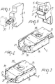
- the safety lock for electrical devices according to the invention is particularly suitable for locking the handle 3 of an electric switch 5, as shown in the present example.
- the handle 3 of the switch 5 has two recesses 7 which are respectively arranged above and below the grip portion 9, so that one recess 7 is always located at lateral holes 11 formed in the body of the switch both when the handle is in the closed-switch position and when it is in the open-switch position.
- FIGS. 1 and 8 illustrate the open-switch position.
- the lock 1 includes a base body 13, a sliding body 15 which can move along the longitudinal axis of the base body 13, and a hook member 17 which is stationary with respect to the base body 13.
- the hook member 17 is constituted by a wire-like body which has two flexible arms 19, each of which has a hook-shaped end 21; the flexible arms are joined by a transverse arm 23 which is rigidly coupled to the base body 13.
- the transverse arm 23 is arranged in a slot which is formed in a block 25 which is rigidly coupled to the base body 13.
- the sliding body 15 includes two shaped walls 27 and a central member 29 which are adapted to guide the movement of the flexible arms 19 of the hook member 17.
- the flexible arms 19 are in fact set at an appropriate angle with respect to the longitudinal axis of the lock, so that a movement of the sliding body 15 with respect to the base body 13 is matched by a movement of the flexible arms 19.
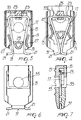
- the flexible arms 19 determine two positions: a closed position (FIGS. 3, 5, 6 and 7), in which the arms are spaced apart and the hook-shaped ends 21 are located outside the tip 31 formed by the front ends of the sliding body 15 and of the base body 13, and an open position (FIGS. 2 and 4), in which the arms are joined and the hook-shaped ends 21 lie inside the tip 31.
- the sliding body 15 In the closed position (FIGS. 3, 5, 6 and 7), the sliding body 15 remains substantially inside the base body 13, so that a hole 33 formed in the base body 13 and a hole 35 formed in the sliding body 15 match up, allowing the insertion of a locking means of the padlock type or the like (FIG. 1) to prevent the opening of the lock, which occurs by sliding the sliding body with respect to the base body, extracting it partially and allowing the arms 19 to join by virtue of the action of the shaped walls 27 on the arms.
- a locking means of the padlock type or the like FIG. 1
- the operation of the lock according to the invention is simple and effective. For example, if one wishes to lock a switch 5 in the open position, shown in FIGS. 1 and 8, it is sufficient to place the lock in the open position (FIGS. 2 and 4), making the sliding body 15 slide backward with respect to the fixed body 13, and then insert the tip 31 in front of the recess 7 of the handle 3. By moving the sliding body 15 into the retracted or closed position (FIGS. 3, 5, 6 and 7), the hook-shaped ends 21 are made to protrude and enter the lateral holes 11 formed in the body of the switch. A padlock 37 or the like, inserted in the holes 33 and 35 of the lock, prevents the sliding of the sliding body 15 with respect to the base body 13 and therefore the extraction of the lock and accordingly prevents unauthorized actuation of the switch.
- the invention achieves the intended aim and object, a safety lock for electrical devices, particularly handle electrical switches, having been provided which allows to lock the switch in a chosen position with an optional key-operated means.
- the materials used, as well as the dimensions, may of course be any according to the requirements and the state of the art.
Landscapes
- Switch Cases, Indication, And Locking (AREA)
- Driving Mechanisms And Operating Circuits Of Arc-Extinguishing High-Tension Switches (AREA)
- Rotary Switch, Piano Key Switch, And Lever Switch (AREA)
Applications Claiming Priority (2)
| Application Number | Priority Date | Filing Date | Title |
|---|---|---|---|
| ITMI980713U | 1998-11-05 | ||
| ITMI980713 IT244350Y1 (it) | 1998-11-05 | 1998-11-05 | Struttura di bloccaggio di sicurezza per apparecchiature elettricheparticolarmente per la maniglia di interruttori elettrici |
Publications (1)
| Publication Number | Publication Date |
|---|---|
| EP0999568A1 true EP0999568A1 (de) | 2000-05-10 |
Family
ID=11379642
Family Applications (1)
| Application Number | Title | Priority Date | Filing Date |
|---|---|---|---|
| EP99115554A Withdrawn EP0999568A1 (de) | 1998-11-05 | 1999-08-06 | Sicherheitsschloss für elektrische Vorrichtungen insbesondere für elektrische Schalter |
Country Status (2)
| Country | Link |
|---|---|
| EP (1) | EP0999568A1 (de) |
| IT (1) | IT244350Y1 (de) |
Cited By (6)
| Publication number | Priority date | Publication date | Assignee | Title |
|---|---|---|---|---|
| EP1371009A4 (de) * | 2001-03-21 | 2007-04-04 | Brady Worldwide Inc | Unterbrecherschalter-lockout-baugruppe |
| DE102009017059B3 (de) * | 2009-04-09 | 2010-07-08 | Siemens Aktiengesellschaft | Anordnung zur Blockierung eines Betätigungselements eines Elektroinstallationsgeräts sowie Elektroinstallationsgerät |
| EP2076913A4 (de) * | 2006-09-18 | 2010-08-04 | Master Lock Co | Schalter-lockout-anordnung |
| DE102009025246A1 (de) * | 2009-06-17 | 2010-12-30 | Siemens Aktiengesellschaft | Anordnung zur Blockierung eines Betätigungselements eines Elektroinstallationsgeräts sowie Elektroinstallationsgerät |
| DE102012110248A1 (de) * | 2012-10-26 | 2014-04-30 | Eaton Industries (Austria) Gmbh | Verschließbare Sperre für einen Leitungsschutzschalter |
| US9208964B2 (en) | 2012-12-14 | 2015-12-08 | Master Lock Company Llc | Lockout device |
Citations (4)
| Publication number | Priority date | Publication date | Assignee | Title |
|---|---|---|---|---|
| GB2027994A (en) * | 1978-04-24 | 1980-02-27 | Merlin Gerin | Handle fastening device for an electrical circuit breaker |
| EP0172771A1 (de) * | 1984-08-08 | 1986-02-26 | Merlin Gerin | Abschliessvorrichtung mit Vorhängeschloss für einen Miniaturschalter |
| DE4101834A1 (de) * | 1991-01-23 | 1992-07-30 | Kloeckner Moeller Gmbh | Verriegelungsvorrichtung fuer leistungsschalter |
| WO1997043776A1 (en) * | 1996-05-14 | 1997-11-20 | Square D Company | Circuit breaker with handle locking device |
-
1998
- 1998-11-05 IT ITMI980713 patent/IT244350Y1/it active
-
1999
- 1999-08-06 EP EP99115554A patent/EP0999568A1/de not_active Withdrawn
Patent Citations (4)
| Publication number | Priority date | Publication date | Assignee | Title |
|---|---|---|---|---|
| GB2027994A (en) * | 1978-04-24 | 1980-02-27 | Merlin Gerin | Handle fastening device for an electrical circuit breaker |
| EP0172771A1 (de) * | 1984-08-08 | 1986-02-26 | Merlin Gerin | Abschliessvorrichtung mit Vorhängeschloss für einen Miniaturschalter |
| DE4101834A1 (de) * | 1991-01-23 | 1992-07-30 | Kloeckner Moeller Gmbh | Verriegelungsvorrichtung fuer leistungsschalter |
| WO1997043776A1 (en) * | 1996-05-14 | 1997-11-20 | Square D Company | Circuit breaker with handle locking device |
Cited By (13)
| Publication number | Priority date | Publication date | Assignee | Title |
|---|---|---|---|---|
| EP1371009A4 (de) * | 2001-03-21 | 2007-04-04 | Brady Worldwide Inc | Unterbrecherschalter-lockout-baugruppe |
| AU2007297352B2 (en) * | 2006-09-18 | 2011-11-03 | Master Lock Company Llc | Switch lockout device |
| CN101826406B (zh) * | 2006-09-18 | 2013-07-24 | 总锁有限责任公司 | 开关锁定装置 |
| EP2076913A4 (de) * | 2006-09-18 | 2010-08-04 | Master Lock Co | Schalter-lockout-anordnung |
| CN101573773B (zh) * | 2006-09-18 | 2012-07-04 | 总锁有限责任公司 | 开关锁定装置 |
| US7977590B2 (en) | 2006-09-18 | 2011-07-12 | Master Lock Company Llc | Switch lockout device |
| CN101859655A (zh) * | 2009-04-09 | 2010-10-13 | 西门子公司 | 用于闭锁电气安装设备操纵元件的装置以及电气安装设备 |
| DE102009017059B3 (de) * | 2009-04-09 | 2010-07-08 | Siemens Aktiengesellschaft | Anordnung zur Blockierung eines Betätigungselements eines Elektroinstallationsgeräts sowie Elektroinstallationsgerät |
| CN101859655B (zh) * | 2009-04-09 | 2014-07-02 | 西门子公司 | 用于闭锁电气安装设备操纵元件的装置以及电气安装设备 |
| DE102009025246B4 (de) * | 2009-06-17 | 2011-07-28 | Siemens Aktiengesellschaft, 80333 | Anordnung zur Blockierung eines Betätigungselements eines Elektroinstallationsgeräts sowie Elektroinstallationsgerät |
| DE102009025246A1 (de) * | 2009-06-17 | 2010-12-30 | Siemens Aktiengesellschaft | Anordnung zur Blockierung eines Betätigungselements eines Elektroinstallationsgeräts sowie Elektroinstallationsgerät |
| DE102012110248A1 (de) * | 2012-10-26 | 2014-04-30 | Eaton Industries (Austria) Gmbh | Verschließbare Sperre für einen Leitungsschutzschalter |
| US9208964B2 (en) | 2012-12-14 | 2015-12-08 | Master Lock Company Llc | Lockout device |
Also Published As
| Publication number | Publication date |
|---|---|
| ITMI980713U1 (it) | 2000-05-05 |
| IT244350Y1 (it) | 2002-03-11 |
Similar Documents
| Publication | Publication Date | Title |
|---|---|---|
| US6886376B2 (en) | Lock for securing an article on display | |
| US9564701B2 (en) | Plug connector | |
| TW354350B (en) | Handleset | |
| AU2003252175A1 (en) | Lock for securing an article on display | |
| EP2101340B1 (de) | Elektrischer Schalter, insbesondere Elektrowerkzeugschalter | |
| US4291207A (en) | Removable push-to-unlock actuator for locking pivoted-subactuator self-enclosed electric switch | |
| EP0976898A3 (de) | Verschlusshandhabe für Kühlgeräte | |
| CA2212298A1 (en) | Door latch operator | |
| US4248465A (en) | Automobile door lock operating tool | |
| US20040112722A1 (en) | Electric switch with a drive shaft and a blocking mechanism for blocking actuation of the drive shaft | |
| RO117579B1 (ro) | Scula de conectare | |
| KR20020023614A (ko) | 도어 잠금장치 | |
| EP4369539A1 (de) | Vorrichtung zum befestigen eines etuis an einer din-schiene und etui mit einer solchen vorrichtung | |
| US5823321A (en) | Locking device for unipolar breaker | |
| AU656139B2 (en) | Improvements in adapters for electrical plugs | |
| CN108292820A (zh) | 包含锁的母连接器插头 | |
| US20250062552A1 (en) | Cable connection device and actuator for a cable connection device | |
| ITMI980713U1 (it) | Struttura di bloccaggio di sicurezza per apparecchiature elettricheparticolarmente per la maniglia di interruttori elettrici | |
| ES8704232A1 (es) | Cerradura electrica bloqueable, principalmente para vehiculo automovil | |
| EP0495564B1 (de) | Klinke für um ein Gelenk drehbares Brett | |
| EP1371310A3 (de) | Sicherheitsschirmständer | |
| JPS5921129B2 (ja) | キ−スイツチ | |
| US20020078724A1 (en) | Tail gate locking apparatus for protecting children | |
| JP3058503U (ja) | 錠止装置を備えたケーシング | |
| KR890003459Y1 (ko) | 창문 괘정구 |
Legal Events
| Date | Code | Title | Description |
|---|---|---|---|
| PUAI | Public reference made under article 153(3) epc to a published international application that has entered the european phase |
Free format text: ORIGINAL CODE: 0009012 |
|
| AK | Designated contracting states |
Kind code of ref document: A1 Designated state(s): DE ES FR GB |
|
| AX | Request for extension of the european patent |
Free format text: AL;LT;LV;MK;RO;SI |
|
| 17P | Request for examination filed |
Effective date: 20001023 |
|
| AKX | Designation fees paid |
Free format text: DE ES FR GB |
|
| 17Q | First examination report despatched |
Effective date: 20060801 |
|
| STAA | Information on the status of an ep patent application or granted ep patent |
Free format text: STATUS: THE APPLICATION IS DEEMED TO BE WITHDRAWN |
|
| 18D | Application deemed to be withdrawn |
Effective date: 20061212 |