EP0999719B1 - Verfahren und Vorrichtung zur Vervollständigung von Fernsprechanrufen zwischen Teilnetzen - Google Patents
Verfahren und Vorrichtung zur Vervollständigung von Fernsprechanrufen zwischen Teilnetzen Download PDFInfo
- Publication number
- EP0999719B1 EP0999719B1 EP19990308694 EP99308694A EP0999719B1 EP 0999719 B1 EP0999719 B1 EP 0999719B1 EP 19990308694 EP19990308694 EP 19990308694 EP 99308694 A EP99308694 A EP 99308694A EP 0999719 B1 EP0999719 B1 EP 0999719B1
- Authority
- EP
- European Patent Office
- Prior art keywords
- call
- interface
- atm
- signaling
- message
- Prior art date
- Legal status (The legal status is an assumption and is not a legal conclusion. Google has not performed a legal analysis and makes no representation as to the accuracy of the status listed.)
- Expired - Lifetime
Links
Images


Classifications
-
- H—ELECTRICITY
- H04—ELECTRIC COMMUNICATION TECHNIQUE
- H04Q—SELECTING
- H04Q11/00—Selecting arrangements for multiplex systems
- H04Q11/04—Selecting arrangements for multiplex systems for time-division multiplexing
-
- H—ELECTRICITY
- H04—ELECTRIC COMMUNICATION TECHNIQUE
- H04Q—SELECTING
- H04Q2213/00—Indexing scheme relating to selecting arrangements in general and for multiplex systems
- H04Q2213/13176—Common channel signaling, CCS7
-
- H—ELECTRICITY
- H04—ELECTRIC COMMUNICATION TECHNIQUE
- H04Q—SELECTING
- H04Q2213/00—Indexing scheme relating to selecting arrangements in general and for multiplex systems
- H04Q2213/13209—ISDN
-
- H—ELECTRICITY
- H04—ELECTRIC COMMUNICATION TECHNIQUE
- H04Q—SELECTING
- H04Q2213/00—Indexing scheme relating to selecting arrangements in general and for multiplex systems
- H04Q2213/13216—Code signals, frame structure
-
- H—ELECTRICITY
- H04—ELECTRIC COMMUNICATION TECHNIQUE
- H04Q—SELECTING
- H04Q2213/00—Indexing scheme relating to selecting arrangements in general and for multiplex systems
- H04Q2213/1329—Asynchronous transfer mode, ATM
-
- H—ELECTRICITY
- H04—ELECTRIC COMMUNICATION TECHNIQUE
- H04Q—SELECTING
- H04Q2213/00—Indexing scheme relating to selecting arrangements in general and for multiplex systems
- H04Q2213/13296—Packet switching, X.25, frame relay
-
- H—ELECTRICITY
- H04—ELECTRIC COMMUNICATION TECHNIQUE
- H04Q—SELECTING
- H04Q2213/00—Indexing scheme relating to selecting arrangements in general and for multiplex systems
- H04Q2213/13383—Hierarchy of switches, main and subexchange, e.g. satellite exchange
-
- H—ELECTRICITY
- H04—ELECTRIC COMMUNICATION TECHNIQUE
- H04Q—SELECTING
- H04Q2213/00—Indexing scheme relating to selecting arrangements in general and for multiplex systems
- H04Q2213/13389—LAN, internet
Definitions
- the present invention relates to the field of providing telephone services using asynchronous transfer mode (ATM) facilities and, in particular, to a method and apparatus for completing telephone calls between ATM subnetworks overlaid on an ATM backbone network.
- ATM asynchronous transfer mode
- Telecommunication service providers are considering using ATM as the technology of choice to consolidate their networking infrastructure under one "umbrella".
- An aim of this activity is to provide ATM switching systems in a networking backbone that can serve as the transport technology for traffic emanating from different sources.
- a second aim of this activity is to allow service providers to maximize their investment in ATM equipment.
- Service providers to date have primarily used ATM networks for data transport. By using ATM networks as a backbone for diverse traffic sources, service providers can expand the usage of their ATM facilities and maximize the return on capital investment made in this equipment.
- a transit trunk subnetwork permits an ATM subnetwork to be integrated into the PSTN using interfaces referred to as "Multi-Service Platforms" (MSPs).
- MSPs provide access to the ATM subnetwork by synchronous transfer mode (STM) switches and convert pulse code modulated (PCM) data to ATM cells and vice versa.
- STM synchronous transfer mode
- PCM pulse code modulated
- the Transit Trunk Subnetwork also includes a call manager which communicates with STM switches through a Common channel Signaling (CCS) network, such as the Signaling System 7 (SS7) network.
- CCS Common channel Signaling
- SS7 Signaling System 7
- the call manager also communicates with the ATM subnetwork through ATM links. Consequently, the call manager is enabled to support PSTN/ISDN intelligent services, while permitting the ATM subnetwork to serve as the transport medium for bearer traffic routed between STM switches in the subnetwork.
- International application number WP 98/23056 describes a system for interfacing an ISDN or non-ISDN system with an ATM system.
- the system can process the ISDN signalling to select ATM connections and then inter-work the ISDN connections with selected ATM connections.
- International application number WO 98/35527 also describes a method for establishing a communication session over a path supported at least in part by a telephony network and an ATM network.
- ISUP Integrated Services Digital Network User Part
- SS7 signaling messages are used to complete calls so that call control signaling is effected without modifying PSTN/ISDN switches served by the subnetworks.
- the invention provides an apparatus for transferring voice or voice grade data using asynchronous transfer mode (ATM) protocol between first and second telephone switches respectively associated with first and second subnetworks adapted to use an ATM backbone network for the transfer of inter-switch bearer traffic, said first telephone switch having a first interface with said first subnetwork and said second telephone switch having a second interface with said second subnetwork, said first and second interfaces being respectively adapted to convert pulse code modulated data to ATM cells and vice versa, CHARACTERIZED by:
- ATM synchronous transfer mode
- the invention also provides a method for routing a telephone call between a first and second telephone switch respectively associated with a first and second subnetwork which use asynchronous transfer mode (ATM) protocol to transfer bearer traffic between telephone switches in the respective subnetworks, said first telephone switch having a first interface with said first subnetwork and said second telephone switch having a second interface with said second subnetwork, first and second call managers being logically associated with said respective first and second subnetworks, CHARACTERIZED by:
- the present invention relates to an apparatus and method for supporting call transfer between transit trunk subnetworks overlaid on an ATM backbone network which provides both narrowband and broadband services.
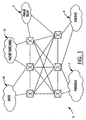
- FIG. 1 is a schematic diagram illustrating an ATM backbone network 5 which supports traffic emanating from different sources.
- the sources of traffic are illustrated as network islands consisting of: a PSTN/ISDN 7; an Internet network 9; a frame relay network 11; a packet switching network 13; and a switched multi-mega bit data service (SMDS) 15.
- the ATM backbone network 5 includes a plurality of ATM switches which are interconnected by ATM links, schematically illustrated by solid lines between the switches.
- FIG. 1 shows six such switches, although an ATM backbone network may include any number of ATM switches, and the physical size of the network is a matter of design choice.
- the ATM backbone network 5 may be used to support a plurality of logical subnetworks for supporting PSTN/ISDN services. Such subnetworks may be the transit trunk subnetworks referred to above and described in Applicant's co-pending patent application.
- FIG. 2 schematically illustrates a network architecture which permits bearer traffic to be routed between two end offices 27 and 29 in the PSTN through an ATM backbone network 25.
- the end offices 27 and 29 are respectively served by different transit trunk subnetworks.
- the ATM backbone network is represented by block 25 and is of indeterminate size.
- the ATM backbone network 25 supports at least a first transit trunk subnetwork 32 and a second transit trunk subnetwork 34, hereinafter referred to as subnetworks 32, 34.
- Each of the subnetworks 32 and 34 are associated with ATM switches that are interconnected by ATM links.
- the first subnetwork 32 and second subnetwork 34 are schematically shown as being interconnected by a link 35, representative of one or more virtual circuits (VCs) that may be established to interconnect the subnetworks 32 and 34.
- VCs virtual circuits
- ATM backbone network 25 Since the ATM backbone network 25 provides only a transport service, it can be abstracted and considered as a single hop between two interfaces which may be considered to be adjacent in the path of the call. This concept leads to the term "ATM trunking", which denotes the use of switched Virtual Channel Connections (VCCs) or switched virtual path connections (VPCs) to carry traffic from one interface at a PSTN/ISDN node to another rather than the usual trunks based on the current PSTN/ISDN hierarchy. Establishment of these ATM "trunks" is done under the control of both ISUP and ATM protocols, as will be further explained below.
- VCCs switched Virtual Channel Connections
- VPCs switched virtual path connections
- MSPs 40 and 42 The interfaces between the end offices 27, 29 and the ATM backbone 25 are hereinafter referred to as Multi-Service Platforms (MSPs) 40 and 42, which are described in further detail in applicant's co-pending application described above.
- MSPs 40 and 42 convert PCM data to ATM cells and vice versa.
- the MSPs 40 and 42 map VCCs, in particular, SVCs set up for transferring bearer traffic between the corresponding trunks 41 and 43 seized at the respective end offices 27 and 29.
- the network architecture of FIG. 2 also includes a first call manager 44 associated with the subnetwork 32 and a second call manager 50 associated with the subnetwork 34.
- Each of the first and second call managers 44 and 50 have a CCS network point code, and are configured to receive and route ISUP signaling messages through the CCS network, as will be further explained below.
- the MSPs 40, 42 and the call managers 44, 50 are illustrated in FIG. 2 as separate entities, it should be understood that they may be implemented on the same platform.
- the call managers may also be implemented within the end offices 27, 29 as explained in Applicant's co-pending United States patent application entitled HYBRID TDM AND ATM VOICE SWITCHING CENTRAL OFFICE AND METHOD OF COMPLETING INTER-OFFICE CALLS USING SAME which was filed on December 7, 1998.
- the network architecture of FIG. 2 further includes CCS signaling links 46 and 52 which permit the end offices 27 and 29 to communicate with the CCS network 58, which typically uses SS7 protocol.
- the first call manager 44 is connected to a CCS signaling link 48, while the second call manager 50 is connected to a CCS signaling link 51.
- Each of the call managers are further connected to ATM links 54 and 56 to permit the first and second-call managers to send control messages to the MSPs 40 and 42.
- CCS messages from both the end offices and call managers are thus routed over the CCS network 58, while control messages for MSPs in the subnetworks 32, 34 are routed through the ATM backbone network 25 using ATM circuits.
- each call manager is configured to engage in ISUP signaling with the CCS network, and control messaging with the subnetworks, but maintains these signaling functions separate from each other.
- This configuration permits the network architecture to support intelligent services derived from the PSTN/ISDN, while using an ATM backbone as the underlying infrastructure for call transport.
- the signaling configuration imposes minimum requirements on the ATM backbone network 25, making the architecture immediately feasible for implementation in the PSTN/ISDN.
- no changes to the CCS protocol is needed, since CCS messaging and ATM control messages are managed separately by each call manager.
- the mechanism used is a messaging parameter used to transfer the information.
- This parameter is referred to as an Application Transport parameter (APP) which is inserted into ISUP signaling messages routed across the CCS network 58 (FIG. 2).
- the APP consists of a plurality of octets which provide various information for signal processing across ATM subnetworks.
- the APP is defined in further detail in Report R-77 of the Telecommunications Standardization Sector of the International Telecommunication Union, published November 1997, which is incorporated herein by reference.
- FIG. 3 provides a schematic diagram of the structure of an APP.
- Each of the first four octets include a one bit extension indicator, which is used to indicate whether further octets exist. This permits expansion of the value range for each field. If the extension indicator is set to "0", a further octet exists. If it is set to "1", no further octet exists.
- the first extension indicator is followed by a seven bit application context identifier which is a value that uniquely identifies the application using the application transport mechanism.
- the second octet includes the one bit extension identifier followed by five spare bits. The following two bits are Application Transport Instruction Indicators (ATII), respectively referred to as "B" and "A".
- ATII Application Transport Instruction Indicators
- Bit B is a Send Notification Indicator which either provides an instruction to send or not send a notification.
- Bit A is a Release Call Indicator which will either indicate an instruction to release or not to release a call.
- Octet 3 has the one bit extension indicator followed by a one bit Sequence Indicator (SI).
- SI is used to indicate the first segment of an Application Transport Message (APM) Segmentation Indicator sequence.
- the APM is a message type described in Report R-77 referred to above and incorporated herein by reference.
- the APM is an ISUP message type which is used for call completion when a VCC is deployed from cache. The use of the APM in call set-up is described in further detail below with reference to Fig. 6.
- the APM Segmentation Indicator indicates the number of remaining segments carrying information used in the APM.
- Octet 3a has the one bit extension indicator, followed by a Segmentation Local Reference (SLR) defined in seven bits.
- SLR Segmentation Local Reference
- the SLR is a unique value assigned to a call and is used to associate segments in a segmented APM.
- the number of segments are defined by the APM Segmentation Indicator in Octet 3.
- Octets 4a through 4n contain Encapsulated Application Information and utilize eight bits in a variable number of octets.
- the Encapsulated Application Information is application information required to be transported by an ISUP Initial Address Message (IAM) or an APM.
- the coding for the Encapsulated Application Information may take several forms.
- the coding may be a tag followed by a length field and a value field; a tag followed by a value field only; or a tag followed by flags.
- the Encapsulated Application Information defines three sets of data required during call set-up. These are:
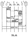
- FIG. 4A illustrates a signalling sequence for setting up calls through the ATM backbone network 25 shown in FIG. 2.
- FIG. 4A illustrates the signalling sequence for connection set-up using VCCs when a call originates at an end office 27 and terminates at an end office 29. It should be understood, however, that analogous principles may be applied when a call is set up across any number of intermediate subnetworks.
- the interface between the originating end office 27 and the first subnetwork is provided by a first MSP 40 and a first call manager 44.
- the interface between the terminating end office 29 and the second subnetwork is provided by a second MSP 42 and a second call manager 50.
- dashed lines are used to indicate ISUP signal messages while solid lines are used to indicate ATM signal messages.
- a call originates at end office 27.
- the originating end office 27 formulates an SS7 IAM and forwards the IAM over the SS7 network to the first call manager 44 associated with the first subnetwork.
- the first call manager 44 extracts call information from the message and formulates an IAM Advisory message (IAM ADV) which it sends through the ATM backbone network 25 to the first MSP 40.
- the MSP 40 responds with an IAM Acknowledge (IAM ACK) which is returned to the first call manager 44.
- the first call manager 44 translates a dialed number extracted from the IAM to obtain routing information for the call.
- the IAM is then modified to include: an originating point code (OPC) of the call manager 44; a destination point code (DPC) of the call manager 42 in the second subnetwork 34; and information to identify features of the first subnetwork 32 related to the call.
- OPC originating point code
- DPC destination point code
- the modified IAM is subsequently sent to the second call manager 50.
- the IAM is modified in part by inserting the APP shown in FIG. 3, which includes the Application Context Identifier and the three pieces of data stored in the Encapsulated Application Information Fields, as described previously. These are:
- the ATM VCC identifier is used in conjunction with the Application Context Identifier as set forth in FIG. 3.
- the Application Context Identifier shown in FIG. 3 provides an indication to the second call manager 50 that an ATM VCC is to be used between the second MSP 42 and first MSP 40 for the transfer of call data but it does not identify a specific ATM VCC to be used for the call.
- the second MSP 42 will either set up a new ATM VCC with the first MSP 40 or select an existing VCC from cache.
- the ATM address of the first MSP 40 identifies where the first MSP 40 is located in the ATM backbone network 25. This information is required by the second MSP 42 to establish a VCC to the first MSP 40.
- the inclusion of the ATM address of the first MSP 40 enables the setup in a backwards direction of the VCC between the two MSPs.
- the Signaling Correlation Tag enables the first MSP 40 to correlate a Set-Up message sent in the backwards direction from the second MSP 42 to the first MSP 40 with the IAM ADV from the first call manager 44 to the first MSP 40. This allows the SVC to be mapped to the TDM trunk at the originating end office seized for the call.
- the IAM Once the IAM has been modified to include the APP, it is routed to the second call manager 50.
- the second call manager 50 sends an IAM ADV to the second MSP 42.
- the second MSP 42 returns an LAM ACK to the second call manager 50.
- the second call manager 50 sends a Connection Request message to the second MSP 42.
- the Connection Request message includes the data from the Encapsulated Application Information field of the APP.
- the second MSP 42 examines the Encapsulated Application Information to determine whether an existing (cached) VCC exists with the first MSP 40, or a new VCC must be established for the call.
- the second MSP 42 formulates a Set-Up message which contains an ATM VCC Identifier selected by the MSP 42 to identify the VCC to be used for the call and the Signaling Correlation Tag from the APP.
- the Set-Up message is routed through the ATM backbone network 25 in a manner well known in the art to a terminating node which serves the first MSP 40.
- the Set-Up message sets up the ATM VCC as a switched virtual circuit (SVC) between the second MSP 42 and the first MSP 40, and is identified to the first MSP 40 by the VCC Identifier.
- SVC switched virtual circuit
- the Signaling Correlation Tag in the Set-Up message is then used by the first MSP 40 to correlate the Setup message to the IAM ADV message previously sent from the first call manager 44 to the first MSP 40. This correlation permits the first MSP 40 to map the SVC set up between the MSPs 42 and 40 to a TDM trunk member seized by the originating office 27 for carrying the call.
- the setup of the SVC is then completed by a Connect message sent from the first MSP 40 to the second MSP 42 along the same path traversed by the Set-Up message, but in the forward direction. This is followed by a Synchronize message sent from the second MSP 42 to the first MSP 40. The Synchronize message tests the integrity of the SVC set up for the call.
- the first MSP 40 responds with a Synchronize Acknowledge message (Synchronize ACK) message sent from the first MSP 40 to the second MSP 42.
- Synchronize ACK Upon receipt of the Synchronize ACK message, the MSP 42 sends a Connection Request Acknowledgement (Connection REQ ACK) to the second call manager 50.
- the second call manager 50 removes the APP data from the IAM and amends the IAM to include a circuit identification code (CIC) of a trunk maintained in a trunk group that connects the end office 29 to the second MSP 42.
- the CIC indicates to the end office 29 the trunk on which the incoming call will arrive.
- the IAM, as amended, is then sent from the second call manager 50 to the terminating end office 29.
- CIC circuit identification code
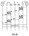
- FIG. 4B illustrates a signaling sequence which is a continuation of the signaling sequence set forth in FIG. 4A.
- the terminating end office verifies that the number is valid and the called line is available. After the verifications are complete, the terminating end office formulates an Address Complete message (ACM) and sends the ACM to the second call manager 50.
- the second call manager 50 then sends an ACM Advisory message (ACM ADV) to the second MSP 42, which responds with an ACM Acknowledge message (ACM ACK).
- ACM Address Complete message
- ACM ADV ACM Advisory message
- the ACM Upon receipt of the ACM ACK, the ACM is forwarded from the second call manager 50 to the first call manager 44, which likewise sends an ACM ADV to the first MSP 40, which returns an ACM ACK.
- the first call manager 44 Upon receipt of the ACM ACK, the first call manager 44 forwards the ACM to the originating end office 27. Receipt of the ACM at the originating end office 27 completes a connection between the calling party line and the called party line. Consequently, ringing applied to the called party line by the terminating end office 29 is heard by the calling party. When the called party answers, an Answer message (ANM) is sent from the terminating end office 29 to the second call manager 50.
- NAM Answer message
- the second call manager 50 responds by sending an ANM Advisory message (ANM ADV) to the second MSP 42, which returns an ANM Acknowledge message (ANM ACK).
- ANM ADV ANM Advisory message
- the second call manager 50 forwards the ANM to the first call manager 44.
- the first call manager 44 sends an ANM ADV to the first MSP 40 which returns an ANM ACK.
- the ANM is then sent from the first call manager 44 to the originating end office 27 and conversation proceeds as for any regular call with the pulse code modulated (PCM) call data being transferred through the ATM backbone network 25.
- PCM pulse code modulated
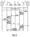
- FIG. 5 illustrates a signaling sequence for taking down calls set-up between originating end office 27 and terminating end office 29, where the bearer traffic of the call is transferred by the ATM backbone network 25.
- the network elements shown in FIG. 5 are identical to the network elements illustrated in FIGS. 4a and 4B.
- a Release message is sent from end office 29 to the second call manager 50 which responds by sending a Release Advisory Message (REL ADV) to the second MSP 42, which returns a Release Acknowledge message (REL ACK).
- REL ADV Release Advisory Message
- the second call manager 50 Upon receipt of the REL ACK, the second call manager 50 forwards the REL message to the first call manager 44, which sends a REL ADV to the first MSP 40, which returns a REL ACK.
- the REL message is then forwarded to the originating end office 27.
- the originating end office 27 responds with a Release Complete message (RLC) to the first call manager 44.
- RLC Release Complete message
- the first call manager 44 responds to receipt of the RLC message by sending an RLC Advisory message (RLC ADV) to the first MSP 40 which returns an RLC Acknowledge message (RLC ACK).
- RLC ADV RLC Advisory message
- the RLC is subsequently sent to the second call manager 50, which forwards the RLC to the terminating end office 29.
- the second call manager 50 also sends an RLC ADV message to the second MSP 42 which responds with an RLC ACK.
- the SVC which was established for the call is released when the first MSP 40 sends a Release SVC message to the second MSP 42 in response to the RLC Advisory message received from the first call manager 40. This is acknowledged by a Release Acknowledge (Release ACK) message sent from the second MSP 42 to the first MSP 40.
- Release ACK Release Acknowledge
- FIG. 6 illustrates a signaling sequence where a call is established through the ATM backbone network 25 and the VCCs used to transfer the bearer traffic are SVCs that were pre-established and stored in a cache.
- This signaling sequence utilizes an APM signaling message which is defined in Report R-77 of the International Telecommunications Union described above, and which is incorporated herein by reference.
- the APM is an ISUP signaling message sent in either direction to convey application information.
- the APP described previously is encoded into the APM in substantially the same manner that it is encoded into an IAM message except that it includes a VCC identifier.
- the APM enables backward call set up between two subnetworks overlaid on the ATM backbone network 25 when a pre-established VCC is selected from cache for carrying bearer traffic associated with a call.
- the APM is an ISUP protocol message
- the data in the APM may be packed into an ATM cell(s) and sent through the ATM backbone 25.
- the signaling sequence illustrates the steps for call setup when the call originates at end office 27 and terminates at end office 29.
- the network configuration is identical to the one described above with reference to FIGs. 4A and 4B.
- a call originates at end office 27, which formulates and sends an IAM to the first call manager 44 in response to digits dialed by a calling party.
- the first call manager 44 extracts call information, formulates an IAM ADV and sends it to the first MSP 40, which returns an IAM ACK.
- the first call manager 44 modifies the IAM to include: an OPC of the first call manager 44; a DPC of the second call manager 50; and information to identify features of the first subnetwork related to the call. This information is defined in part by the Encapsulated Application Information Fields of the APP, as described above.
- the IAM is sent from the first call manager 44 to the second call manager 50.
- the second call manager 50 Upon receipt of the IAM, the second call manager 50 sends an IAM ADV to the second MSP 42 which responds with an IAM ACK.
- the second call manager 50 Upon receipt of the IAM ACK, the second call manager 50 formulates and sends a Connection Request message to the second MSP 42.
- the Connection Request message includes the Encapsulated Application Information extracted from the IAM.
- the second MSP 42 On receipt of the Connection Request message, the second MSP 42 examines the Encapsulated Application Information to determine whether a pre-established (cached) VCC exists for the ATM address of the first MSP 40. In the present example, it is assumed that an idle cached VCC exists and that it is selected for the call. SVC caching is described in detail in Applicant's co-pending United States patent application entitled METHOD AND APPARATUS FOR REDUCTION OF CALL SETUP RATE IN ATM NETWORK which was filed on October 2, 1998, the entire specification of which is incorporated herein by reference. The second MSP 42 formulates an APM message containing an APP which is encoded with two pieces of data in the Encapsulated Application Information Field.
- the first is the ATM VCC Identifier, which identifies an available SVC in the cache pool to carry the bearer traffic associated with the call.
- the second is the Signaling Correlation Tag which will correlate the APM to an IAM ADV previously sent from the first call manager 44 to the first MSP 40.
- the ATM VCC Identifier permits the first MSP 40 to select the available SVC to carry the bearer traffic for the call.
- the Signal Correlation Tag permits the first MSP 40 to also correlate the APM message to the IAM ADV previously sent from the originating end office 27 to the first MSP 40. This correlation permits the SVC selected from cache to be mapped to the TDM trunk seized at the originating end office.
- the first MSP 40 then sends a Synchronize message to the second MSP 42.
- the Synchronize message tests the integrity of the SVC connection, and is followed by a Synchronize ACK returned by the second MSP 42. Subsequently, the second MSP 42 sends a Connection REQ ACK to the second call manager 50.
- the second call manager 50 When the second call manager 50 receives the Connection REQ ACK message, it inserts CIC information into the IAM to identify a TDM trunk member in a trunk group that connects the second MSP 42 to the terminating end office 29. The IAM with the CIC information is then sent from the second call manager 50 to the terminating end office 29. Subsequently, call processing proceeds in a manner identical to that described above with reference to FIG. 4B.
- Call release procedures for calls set up using SVCs from cache follow substantially the same signaling sequence as illustrated in FIG. 5.
- a decision must be made as to whether the SVC used for the call is to be returned to the cache or released. If the SVC is to be returned to cache, a one of the two MSPs, the first MSP 40, for example, which serves as master of the cache pool sends a Cache SVC message (not shown) to the second MSP 42 and changes the status of the SVC in the cache to "idle". Otherwise, a Release SVC message is sent from the first MSP 40 to the second MSP 42, which instructs the second MSP to release the SVC. The Release SVC message is acknowledge by a Release ACK to complete the SVC release.
- PSTN signaling assumes a use of ISUP protocol
- other signaling protocols which are enabled to control call flow through a switched telephone network could also be used.
- CCS network is described as the preferred path for signaling messages exchanged between the PSTN telephone switches and the call managers 44, 50
- the ATM backbone network 25 could also be used to transfer signaling messages.
- the PSTN telephone switches are provided with ATM interfaces in a manner well known in the art.
- Each of the trunk subnetworks include a call manager which is configured for exchanging signaling messages with both a common channel signaling network and the ATM backbone network.
- This permits ATM facility providers to link subnetworks using a common infrastructure so that calls can be effectively diverted from the PSTN between end offices while fully supporting PSTN/ISDN services.
- This is achieved by using a signaling method in which call request messages are encoded by a first call manager with a parameter so that a second call manager in the signaling path can effect backward call set up between ATM interfaces using data from the parameter.
- the advantage is the extension of call completion between subnetworks overlaid on an ATM backbone using ATM facilities without sacrificing PSTN/ISDN call features.
Landscapes
- Engineering & Computer Science (AREA)
- Computer Networks & Wireless Communication (AREA)
- Data Exchanges In Wide-Area Networks (AREA)
- Telephonic Communication Services (AREA)
Claims (21)
- Vorrichtung zur Übertragung von Sprache oder Sprachqualitäts-Daten unter Verwendung eines asynchronen Übertragungsbetriebsart, nachfolgend als ATM-, Protokoll bezeichnet, zwischen ersten und zweiten Telefonvermittlungen (27, 29), die jeweils ersten und zweiten Teil-Netzwerken (32, 34) zugeordnet sind, die so ausgebildet sind, dass sie ein ATM-Backbone-Netzwerk (25) für die Übertragung von Zwischenvermittlungs-Trägerverkehr verwenden, wobei die erste Telefonvermittlung (27) eine erste Schnittstelle (40) mit dem ersten Teil-Netzwerk (32) aufweist und die zweite Telefonvermittlung (29) eine zweite Schnittstelle (42) mit dem zweiten Teil-Netzwerk (34) aufweist, wobei die ersten und zweiten Schnittstellen (40, 42) jeweils so ausgebildet sind, dass sie pulscodemodulierte Daten in ATM-Zeilen und umgekehrt umwandeln, gekennzeichnet durch:eine erste Verbindungsverwaltung (44), die logisch dem ersten Teil-Netzwerk (32) zugeordnet ist;eine zweite Verbindungsverwaltung (50), die logisch dem zweiten Teil-Netzwerk (34) zugeordnet ist;wobei die ersten und zweiten Verbindungsverwaltungen (44, 50) zum Austausch von Signalisierungsmitteilungen fähig sind, wobei die Signalisierungsmitteilungen Informationen zum Bewirken eines Verbindungsaufbaus zwischen den ersten und zweiten Schnittstellen (40, 42) enthalten;
wobei die erste Verbindungsverwaltung (44) so ausgebildet ist, dass sie eine Signalisierungsmitteilung von der ersten Vermittlung (27) empfängt und einen Inhalt der Signalisierungsmitteilung so modifiziert, dass sie Information bezüglich der ersten Schnittstelle (40) einschließt, die erforderlich ist, um eine der Signalisierungsmitteilung zugeordnete Verbindung aufzubauen, wobei die Information eine ATM-Adresse der ersten Schnittstelle (40) in dem ersten Teil-Netzwerk (32) umfasst. - Vorrichtung nach Anspruch 1, bei der der Verbindungsaufbau in einer Rückwärtsrichtung bezüglich des Verbindungspfades bewirkt wird, wobei der Verbindungsaufbau von der zweiten Schnittstelle (42) zu der ersten Schnittstelle (40) bewirkt wird.
- Vorrichtung nach Anspruch 1 oder 2, bei der die Signalisierungsmitteilungen über das ATM-Backbone-Netzwerk (25) ausgetauscht werden.
- Vorrichtung nach einem der vorhergehenden Ansprüche, bei der die Signalisierungsmitteilungen unter Verwendung eines zentralen Signalisierungskanal-Netzwerkes (58) ausgetauscht werden.
- Vorrichtung nach Anspruch 4, bei der das zentrale Signalisierungskanal-Netzwerk (58) ein Signalisierungssystem 7 ist, das nachfolgend als SS7 bezeichnet wird.
- Vorrichtung nach Anspruch 5, bei der die SS7-Signalisierungsmitteilungen einen ISDN-Benutzerteil-Mitteilungen umfassen, die nachfolgend als ISUP-Mitteilungen bezeichnet werden.
- Vorrichtung nach Anspruch 5 oder 6, bei der die SS7-Signalisierungsmitteilungen Anfangsadressen-Mitteilungen umfassen, die nachfolgend als IAM's bezeichnet werden.
- Vorrichtung nach Anspruch 7, bei der die Signalisierungsmitteilung eine IAM ist und die erste Verbindungsverwaltung (44) so ausgebildet ist, dass sie die IAM von der ersten Vermittlung (27) empfängt und den Inhalt der IAM so modifiziert, dass diese die Information bezüglich der ersten Schnittstelle (40) enthält, die erforderlich ist, um eine der IAM zugeordnete Verbindung aufzubauen.
- Vorrichtung nach Anspruch 8, bei der die zweite Verbindungsverwaltung (50) so konfiguriert ist, dass sie ATM-Mitteitungen mit der zweiten Schnittstelle (42) zur Einleitung einer Rückwärtsverbindung austauscht, die zwischen der zweiten Schnittstelle (42) und der ersten Schnittstelle (40) als Antwort auf die modifizierte IAM aufgebaut wird.
- Vorrichtung nach Anspruch 9, bei der die sich auf die erste Schnittstelle (40) beziehende Information eine Korrelations-Marke umfasst, um eine Korrelation zwischen einer Mitteilung bezüglich der IAM, die von der ersten Verbindungsverwaltung (44) an die ersten Schnittstelle (40) gesandt wurde, und einer Mitteilung bezüglich der IAM, die von der zweiten Schnittstelle (42) an die erste Schnittstelle (40) gesandt wurde, zu ermöglichen.
- Vorrichtung nach Anspruch 10, bei der die zweite Verbindungsverwaltung (50) so ausgebildet ist, dass sie die IAM weiter modifiziert und die weiter modifizierte IAM an die zweite Telefonvermittlung (29) weiterleitet, um eine Fernleitungs-Belegung für die Verbindung einzuleiten.
- Vorrichtung nach Anspruch 11, bei der die zweite Schnittstelle (42) so konfiguriert ist, dass sie einen Rückwärts-Verbindungsaufbau durch Lenken von Mitteilungen über das ATM-Backbone-Netzwerk (25) von der zweiten Schnittstelle (42) an die erste Schnittstelle (40) bewirkt, um das Ausführen von virtuellen Kanalverbindungen zwischen den ersten und zweiten Schnittstellen (40, 42) zu ermöglichen.
- Verfahren zum Lenken einer Telefonverbindung zwischen einer ersten und zweiten Telefonvermittlung (27, 29), die jeweils einem ersten und einem zweiten Teil-Netzwerk (32, 34) zugeordnet sind, die das asynchrone Übertragungsbetriebsart- (ATM-) Protokoll zur Übertragung von Trägerverkehr zwischen Telefonvermittlungen in den jeweiligen Teil-Netzwerken verwenden, wobei die erste Telefonvermittlung (27) eine erste Schnittstelle (40) mit dem ersten Teil-Netzwerk (32) aufweist und die zweite Telefonvermittlung (34) eine zweite Schnittstelle (42) mit dem zweiten Teil-Netzwerk (34) aufweist, wobei erste und zweite Verbindungsverwaltungen (44, 50) logisch den jeweiligen ersten und zweiten Teil-Netzwerken (32, 34) zugeordnet sind, gekennzeichnet durch:(i) Lenken einer Verbindungs-Anforderungsmitteilung von der ersten Telefonvermittlung (27) an die erste Verbindungsverwaltung (44);(ii) Übersetzen einer gewählten Nummer, die aus der Verbindungs-Anforderungsmitteilung abgeleitet wurde, um Routenführungs-information für die Verbindung zu gewinnen;(iii) Modifizieren der Anruf-Anforderungsmitteiiung derart, dass sie Informationen bezüglich des Ursprunges der Verbindung einschließt, und Weiterleiten der modifizierten Anruf-Anforderungsmitteilung an die zweite Verbindungsverwaltung (45) unter Verwendung der Routenführungsinformation für die Verbindungs-Anforderungsmitteilung, wobei die sich auf den Ursprung der Verbindung beziehende Information eine ATM-Adresse der ersten Schnittstelle (40) umfasst;(iv) Übersetzen der gewählten Nummer, die von der modifizierten Verbindungs-Anforderungsmitteilung abgeleitet wurde, an der zweiten Verbindungsverwaltung (50), zur Identifikation der zweiten Telefonvermittlung (29);(v) Senden einer Signalisierungsmitteilung von der zweiten Verbindungsverwaltung (50) an die zweite Schnittstelle (42), wobei die Signalisierungsmitteilung die sich auf den Ursprung der Verbindung beziehende Information einschließt;(vi) Senden einer Signalisierungsmitteilung von der zweiten Schnittstelle (42) an die erste Schnittstelle (40) zum Bewirken einer Verbindung zur Übertragung von Trägerverkehr, der der Verbindung zugeordnet ist; und(vii) weiteres Modifizieren der Verbindungs-Anforderungsmitteilung und Weiterleitung der weiter modifizierten Verbindungs-Anforderungsmitteilung von der zweiten Verbindungsverwaltung (50) an die zweite Telefonvermittlung (29), um die Belegung einer Femleitung an der zweiten Vermittlung (29) einzuleiten, um den Abschluss des Verbindungsaufbaus zu ermöglichen.
- Verfahren nach Anspruch 13, bei dem die Verbindungs-Anforderungsmitteilungen gemeinsame Signalisierungskanal-Mitteilungen sind.
- Verfahren nach Anspruch 14, bei dem die Verbindungs-Anforderungsmitteilungen SS7-Anfangsadressen-Mitteilungen (IAM) sind.
- Verfahren nach Anspruch 13, bei dem der Schritt der Modifikation der Anruf-Anforderungsmitteilung weiterhin Folgendes umfasst:Einfügen einer Korrelationsmarke, um eine Korrelation an der ersten Schnittstelle (40) zwischen einer Mitteilung, die auf die modifizierte Verbindungs-Anforderungsmitteilung bezogen ist, mit der Signalisierungsmitteilung zu ermöglichen, die von der zweiten Schnittstelle (42) an die erste Schnittstelle (40) gesandt wurde.
- Verfahren nach einem der Ansprüche 13-16, bei dem die Signalisierungsmitteilung, die von der zweiten Schnittstelle (42) an die erste Schnittstelle (40) gesandt wird, die Ausführung virtueller Kanalverbindungen zwischen den ersten und zweiten Teil-Netzwerken (32, 34) zur Übertragung von Trägerverkehr, der der Verbindung zugeordnet ist, durch das ATM-Backbone-Netzwerk (25) zu ermöglichen.
- Verfahren nach einem der Ansprüche 13-17, bei dem die Signalisierungsmitteilung, die von der zweiten Schnittstelle (42) an die erste Schnittstelle (40) gesandt wird, eine vorhandene virtuelle Kanalverbindung durch das ATM-Backbone-Netzwerk (25) zur Übertragung des Trägerverkehrs identifiziert.
- Verfahren nach einem der Ansprüche 13, 16-18, bei dem die Signalisierungsmitteilungen ATM-Signalisierungsmitteilungen sind.
- Verfahren nach einem der Ansprüche 13-18, bei dem die Verbindungs-Anforderungsmitteilung eine ISUP-Signalsierungsmitteilung ist.
- Kommunikations-Netzwerk, das die Vorrichtung nach den Ansprüchen 1-12 umfasst.
Applications Claiming Priority (4)
| Application Number | Priority Date | Filing Date | Title |
|---|---|---|---|
| US10674198P | 1998-11-02 | 1998-11-02 | |
| US106741P | 1998-11-02 | ||
| US213769 | 1998-12-17 | ||
| US09/213,769 US6757285B1 (en) | 1998-12-17 | 1998-12-17 | Method and apparatus for completing telephone calls between subnetworks |
Publications (3)
| Publication Number | Publication Date |
|---|---|
| EP0999719A2 EP0999719A2 (de) | 2000-05-10 |
| EP0999719A3 EP0999719A3 (de) | 2003-01-22 |
| EP0999719B1 true EP0999719B1 (de) | 2006-04-19 |
Family
ID=26803976
Family Applications (1)
| Application Number | Title | Priority Date | Filing Date |
|---|---|---|---|
| EP19990308694 Expired - Lifetime EP0999719B1 (de) | 1998-11-02 | 1999-11-02 | Verfahren und Vorrichtung zur Vervollständigung von Fernsprechanrufen zwischen Teilnetzen |
Country Status (4)
| Country | Link |
|---|---|
| EP (1) | EP0999719B1 (de) |
| JP (1) | JP4469039B2 (de) |
| CA (1) | CA2288356C (de) |
| DE (1) | DE69930910T2 (de) |
Family Cites Families (3)
| Publication number | Priority date | Publication date | Assignee | Title |
|---|---|---|---|---|
| US6430195B1 (en) * | 1994-05-05 | 2002-08-06 | Sprint Communications Company L.P. | Broadband telecommunications system interface |
| US5940491A (en) * | 1996-02-29 | 1999-08-17 | Lucent Technologies Inc. | Control of telecommunications networks |
| US5956334A (en) * | 1997-02-10 | 1999-09-21 | At & T Corporation | Method for interfacing a telephony and an ATM network to establish voice communication |
-
1999
- 1999-11-02 DE DE1999630910 patent/DE69930910T2/de not_active Expired - Fee Related
- 1999-11-02 CA CA 2288356 patent/CA2288356C/en not_active Expired - Lifetime
- 1999-11-02 EP EP19990308694 patent/EP0999719B1/de not_active Expired - Lifetime
- 1999-11-02 JP JP31224999A patent/JP4469039B2/ja not_active Expired - Fee Related
Also Published As
| Publication number | Publication date |
|---|---|
| EP0999719A2 (de) | 2000-05-10 |
| CA2288356C (en) | 2009-07-07 |
| JP2000188601A (ja) | 2000-07-04 |
| DE69930910T2 (de) | 2006-09-14 |
| CA2288356A1 (en) | 2000-05-02 |
| EP0999719A3 (de) | 2003-01-22 |
| JP4469039B2 (ja) | 2010-05-26 |
| DE69930910D1 (de) | 2006-05-24 |
Similar Documents
| Publication | Publication Date | Title |
|---|---|---|
| US6195714B1 (en) | System for transferring STM calls through ATM network by converting the STM calls to ATM and vice versa at the edge nodes of ATM network | |
| US6081525A (en) | Broadband telecommunications system | |
| US6026091A (en) | ATM gateway system | |
| US6389130B1 (en) | Public switched telephone network call routing using dyamic asynchronous mode transfer bearer voice trunking | |
| US6069947A (en) | Communication system architecture and operating protocol therefor | |
| US6496508B1 (en) | Communication system architecture and method of establishing a communication connection therein | |
| EP0989771B1 (de) | System bestehend aus einem Durchgangsleitungssubnetzwerk | |
| JP3833718B2 (ja) | 広帯域電気通信システム | |
| JP2002501326A (ja) | チャネルデータ形式で受信されたサービス要求を処理するための仮想搬送チャネルプラットフォーム | |
| US6570868B1 (en) | System and method for establishing a communication connection | |
| JP2002501335A (ja) | 仮想搬送チャネルプラットフォームのためのプログラム可能ゲートウェイ | |
| US6757285B1 (en) | Method and apparatus for completing telephone calls between subnetworks | |
| CA2289401C (en) | Apparatus and method for completing inter-switch calls using large trunk groups | |
| JP2002501327A (ja) | 仮想搬送チャネルプラットフォームのための資源管理部 | |
| WO2001011825A2 (en) | Communications using hybrid circuit-switched and packet-switched networks | |
| US6930998B1 (en) | Hybrid TDM and ATM voice switching central office and method of completing inter-office calls using same | |
| EP0999719B1 (de) | Verfahren und Vorrichtung zur Vervollständigung von Fernsprechanrufen zwischen Teilnetzen | |
| EP1091552A2 (de) | Verfahren und Gerät für Telefondiensten unter Verwendung von TDM Vermittlungsstelle und Datennetze | |
| CN100471286C (zh) | 窄带应用与宽带传输相结合 | |
| US7006493B1 (en) | Virtual voice port configured to connect a switched voice call to a permanent voice call | |
| FI107216B (fi) | Merkinanto televiestintäjärjestelmässä | |
| Smouts et al. | Packet switching fully integrated in ISDN | |
| Kim et al. | PSTN call control over ATM switching system | |
| GB2350254A (en) | Signalling in a telecommunications network | |
| KR20020004402A (ko) | 협대역망과 비동기전송모드망간 연동방법 |
Legal Events
| Date | Code | Title | Description |
|---|---|---|---|
| PUAI | Public reference made under article 153(3) epc to a published international application that has entered the european phase |
Free format text: ORIGINAL CODE: 0009012 |
|
| AK | Designated contracting states |
Kind code of ref document: A2 Designated state(s): AT BE CH CY DE DK ES FI FR GB GR IE IT LI LU MC NL PT SE |
|
| AX | Request for extension of the european patent |
Free format text: AL;LT;LV;MK;RO;SI |
|
| RAP1 | Party data changed (applicant data changed or rights of an application transferred) |
Owner name: NORTEL NETWORKS LIMITED |
|
| PUAL | Search report despatched |
Free format text: ORIGINAL CODE: 0009013 |
|
| AK | Designated contracting states |
Kind code of ref document: A3 Designated state(s): AT BE CH CY DE DK ES FI FR GB GR IE IT LI LU MC NL PT SE |
|
| AX | Request for extension of the european patent |
Free format text: AL;LT;LV;MK;RO;SI |
|
| RIC1 | Information provided on ipc code assigned before grant |
Free format text: 7H 04Q 11/04 A, 7H 04L 12/56 B |
|
| 17P | Request for examination filed |
Effective date: 20030627 |
|
| AKX | Designation fees paid |
Designated state(s): DE FR GB SE |
|
| RAP1 | Party data changed (applicant data changed or rights of an application transferred) |
Owner name: NORTEL NETWORKS LIMITED |
|
| 17Q | First examination report despatched |
Effective date: 20050301 |
|
| GRAP | Despatch of communication of intention to grant a patent |
Free format text: ORIGINAL CODE: EPIDOSNIGR1 |
|
| GRAS | Grant fee paid |
Free format text: ORIGINAL CODE: EPIDOSNIGR3 |
|
| GRAA | (expected) grant |
Free format text: ORIGINAL CODE: 0009210 |
|
| AK | Designated contracting states |
Kind code of ref document: B1 Designated state(s): DE FR GB SE |
|
| REG | Reference to a national code |
Ref country code: GB Ref legal event code: FG4D |
|
| REF | Corresponds to: |
Ref document number: 69930910 Country of ref document: DE Date of ref document: 20060524 Kind code of ref document: P |
|
| REG | Reference to a national code |
Ref country code: SE Ref legal event code: TRGR |
|
| ET | Fr: translation filed | ||
| PG25 | Lapsed in a contracting state [announced via postgrant information from national office to epo] |
Ref country code: SE Free format text: LAPSE BECAUSE OF NON-PAYMENT OF DUE FEES Effective date: 20061103 |
|
| PLBE | No opposition filed within time limit |
Free format text: ORIGINAL CODE: 0009261 |
|
| STAA | Information on the status of an ep patent application or granted ep patent |
Free format text: STATUS: NO OPPOSITION FILED WITHIN TIME LIMIT |
|
| 26N | No opposition filed |
Effective date: 20070122 |
|
| PG25 | Lapsed in a contracting state [announced via postgrant information from national office to epo] |
Ref country code: DE Free format text: LAPSE BECAUSE OF NON-PAYMENT OF DUE FEES Effective date: 20070601 |
|
| EUG | Se: european patent has lapsed | ||
| GBPC | Gb: european patent ceased through non-payment of renewal fee |
Effective date: 20061102 |
|
| REG | Reference to a national code |
Ref country code: FR Ref legal event code: ST Effective date: 20070731 |
|
| PG25 | Lapsed in a contracting state [announced via postgrant information from national office to epo] |
Ref country code: GB Free format text: LAPSE BECAUSE OF NON-PAYMENT OF DUE FEES Effective date: 20061102 |
|
| PG25 | Lapsed in a contracting state [announced via postgrant information from national office to epo] |
Ref country code: FR Free format text: LAPSE BECAUSE OF NON-PAYMENT OF DUE FEES Effective date: 20061130 |