EP0999960B1 - Dispositif essuie-glace pour vehicules - Google Patents
Dispositif essuie-glace pour vehicules Download PDFInfo
- Publication number
- EP0999960B1 EP0999960B1 EP98946223A EP98946223A EP0999960B1 EP 0999960 B1 EP0999960 B1 EP 0999960B1 EP 98946223 A EP98946223 A EP 98946223A EP 98946223 A EP98946223 A EP 98946223A EP 0999960 B1 EP0999960 B1 EP 0999960B1
- Authority
- EP
- European Patent Office
- Prior art keywords
- wiping
- parked
- wiper
- lip
- controller
- Prior art date
- Legal status (The legal status is an assumption and is not a legal conclusion. Google has not performed a legal analysis and makes no representation as to the accuracy of the status listed.)
- Expired - Lifetime
Links
- 238000000034 method Methods 0.000 claims description 7
- 230000008859 change Effects 0.000 claims description 2
- 230000003442 weekly effect Effects 0.000 claims description 2
- 238000012546 transfer Methods 0.000 description 4
- 230000008901 benefit Effects 0.000 description 3
- 230000005540 biological transmission Effects 0.000 description 2
- 238000013461 design Methods 0.000 description 2
- 230000008569 process Effects 0.000 description 2
- 230000002441 reversible effect Effects 0.000 description 2
- 238000013459 approach Methods 0.000 description 1
- 238000004140 cleaning Methods 0.000 description 1
- 230000000694 effects Effects 0.000 description 1
- 230000003287 optical effect Effects 0.000 description 1
- 230000002085 persistent effect Effects 0.000 description 1
- 238000003825 pressing Methods 0.000 description 1
- 230000002035 prolonged effect Effects 0.000 description 1
- 230000033764 rhythmic process Effects 0.000 description 1
- 238000012549 training Methods 0.000 description 1
- 230000007704 transition Effects 0.000 description 1
- 230000001960 triggered effect Effects 0.000 description 1
Images

Classifications
-
- B—PERFORMING OPERATIONS; TRANSPORTING
- B60—VEHICLES IN GENERAL
- B60S—SERVICING, CLEANING, REPAIRING, SUPPORTING, LIFTING, OR MANOEUVRING OF VEHICLES, NOT OTHERWISE PROVIDED FOR
- B60S1/00—Cleaning of vehicles
- B60S1/02—Cleaning windscreens, windows or optical devices
- B60S1/04—Wipers or the like, e.g. scrapers
- B60S1/06—Wipers or the like, e.g. scrapers characterised by the drive
- B60S1/08—Wipers or the like, e.g. scrapers characterised by the drive electrically driven
-
- B—PERFORMING OPERATIONS; TRANSPORTING
- B60—VEHICLES IN GENERAL
- B60S—SERVICING, CLEANING, REPAIRING, SUPPORTING, LIFTING, OR MANOEUVRING OF VEHICLES, NOT OTHERWISE PROVIDED FOR
- B60S1/00—Cleaning of vehicles
- B60S1/02—Cleaning windscreens, windows or optical devices
- B60S1/04—Wipers or the like, e.g. scrapers
-
- B—PERFORMING OPERATIONS; TRANSPORTING
- B60—VEHICLES IN GENERAL
- B60S—SERVICING, CLEANING, REPAIRING, SUPPORTING, LIFTING, OR MANOEUVRING OF VEHICLES, NOT OTHERWISE PROVIDED FOR
- B60S1/00—Cleaning of vehicles
- B60S1/02—Cleaning windscreens, windows or optical devices
- B60S1/04—Wipers or the like, e.g. scrapers
- B60S1/0452—Position of the wipers relative to the vehicle
- B60S1/0455—Device for lifting the wipers off the screen in its parking position or at extremes of wipe
-
- B—PERFORMING OPERATIONS; TRANSPORTING
- B60—VEHICLES IN GENERAL
- B60S—SERVICING, CLEANING, REPAIRING, SUPPORTING, LIFTING, OR MANOEUVRING OF VEHICLES, NOT OTHERWISE PROVIDED FOR
- B60S1/00—Cleaning of vehicles
- B60S1/02—Cleaning windscreens, windows or optical devices
- B60S1/04—Wipers or the like, e.g. scrapers
- B60S1/32—Wipers or the like, e.g. scrapers characterised by constructional features of wiper blade arms or blades
- B60S1/38—Wiper blades
-
- B—PERFORMING OPERATIONS; TRANSPORTING
- B60—VEHICLES IN GENERAL
- B60S—SERVICING, CLEANING, REPAIRING, SUPPORTING, LIFTING, OR MANOEUVRING OF VEHICLES, NOT OTHERWISE PROVIDED FOR
- B60S1/00—Cleaning of vehicles
- B60S1/02—Cleaning windscreens, windows or optical devices
- B60S1/04—Wipers or the like, e.g. scrapers
- B60S1/32—Wipers or the like, e.g. scrapers characterised by constructional features of wiper blade arms or blades
- B60S1/38—Wiper blades
- B60S2001/3827—Wiper blades characterised by the squeegee or blade rubber or wiping element
- B60S2001/3836—Wiper blades characterised by the squeegee or blade rubber or wiping element characterised by cross-sectional shape
-
- Y—GENERAL TAGGING OF NEW TECHNOLOGICAL DEVELOPMENTS; GENERAL TAGGING OF CROSS-SECTIONAL TECHNOLOGIES SPANNING OVER SEVERAL SECTIONS OF THE IPC; TECHNICAL SUBJECTS COVERED BY FORMER USPC CROSS-REFERENCE ART COLLECTIONS [XRACs] AND DIGESTS
- Y10—TECHNICAL SUBJECTS COVERED BY FORMER USPC
- Y10S—TECHNICAL SUBJECTS COVERED BY FORMER USPC CROSS-REFERENCE ART COLLECTIONS [XRACs] AND DIGESTS
- Y10S318/00—Electricity: motive power systems
- Y10S318/02—Windshield wiper controls
Definitions
- the invention is based on a wiper device for windows of vehicles according to the preamble of the main claim.
- wipers for vehicle windows on the market which has a drive motor for driving a wiper have a wiper blade with elastically deformable Wiper lip and a support arm for the wiper blade.
- the support arm is pivoted against the disc by a spring and the wiper lip pressed against the window and deformed. If the wiper is in the park position, then the wiping lip is affected by the intense exposure to sunlight, Heavy heat and cold, so it too a prolonged or permanent deformation of the Wiper lip comes, which leads to insufficient cleaning of the Disc leads.
- noise problems arise from the Slip-stick effect when wiping on, as that deformed Wiper blade no longer adapts flexibly to the wiping direction.
- a wiper system which to avoid deformation of the wiper lip on the support arm Attacking adjusting device that in the park position of the wiper against the force of the spring pivoted and the contact pressure of the wiper lip the disc is reduced or canceled.
- the adjustment device has a protruding into the path of movement of the support arm Ramp firmly supported perpendicular to the pane, onto which the Support arm runs up when the parking position is reached.
- Another disadvantage is that by lifting the Carrier arm of the wiper an increased space requirement, in particular the overall height of the mixing plant, so that the outer or interior design of the vehicle to accommodate the Wiper system must be changed. This is from optical or economic reasons by the vehicle manufacturer he wishes.
- FR-A-2 714 641 is a wiping device and a method for Wiping device known, which has the features of the preambles of claims 1 and 6 shows.
- the wiper device according to the invention with the characteristic Features of the main claim has the advantage of being longer persistent or permanent deformation of an am Wiper blade shaped elastically deformable wiper lip in to avoid parking the wiper by placing it in the Parking position is stored in different parking positions.
- the parking positions of the wiper lip Correspond to the drag positions of the wiper lip when wiping back and forth.
- the parking positions of the wiper lip therefore arise in a simple way due to the different starting the parking position of the wiper by a control.
- the wiper lip is therefore in the parking position in parking positions, which comes directly from the dragging position of the wiper lip Wipe result and therefore without additional tools are preserved.
- control last realized parking position of the wiper lip in the parking position and stores and depending on this and in the Control stored the wiper lip in the further parking position, so that the parking positions alternate. This happens especially in the following Approaching the parking lot or when starting up the parking lot after a predetermined time interval from the last time Alternation.
- a rotary motor as the drive motor or a reversing motor can be used.
- Another advantage is the fact that when not in use the wiping device during a longer predetermined Period of e.g. a month and when in use a reversing motor that controls the parking position of the wiper lip changes without the wiping mode being switched on must become. This is how the wiper lip gets in the rainless Summer months also saved from permanent deformation. When using a rotary motor, this is only when changing from a first to a second parking position possible. The transition in the opposite direction from the second into the first parking position is done via the Triggering a wiping cycle.
- FIG. 1 shows a schematic representation of the Wiper device according to the invention
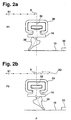
- Figure 2 cross sections through a wiper blade with a shaped wiper lip in a first and second parking position
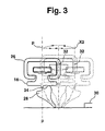
- FIG. 3 the turning process the wiper lip over a transfer bridge at one Change of wiping direction to move to the second parking position.
- the wiper device has a motor 10 on the connection 12 shown by dashed lines drives a wiper 14.
- the wiper 14 has a Wiper blade 16 with which a disc 18 in the area of a Wiping field 20 wiped between two reversal positions U1, U2 becomes.
- the motor 10 is controlled by a controller 22 in different ways Wipers controlled, which in turn can be specified manually by an operating switch 24.
- the wiper 14 is moved into a parking position P when the Wiping operation of the wiper 14 switched off or at one Intermittent operation is interrupted. In the latter the Wiper 14 between the individual wiping cycles of the interval operation parked in the parking area P.
- the parking position P is usually at the bottom of the disk 18 near the Window bezel 30.
- a reversing motor is used as the motor 10, for example via a rotatable engine crank, not shown and a pendulum gear as connection 12, the wiper 14 drives pendulum.
- the connection 12 consists of the wiper 14 directly on to attach the output shaft of the motor 10 so that by Varying the angle of rotation of the engine output shaft the parking positions can be approached in parking position P.
- Figure 2a shows a first
- Figure 2b shows a second parking position P1, P2 of the wiper blade 16 in the park position P.
- Das Wiper blade 16 is fastened to wiper 14 in a holder 26.
- a wiper lip 28 is formed on the wiper blade 16. The wiper lip 28 is in the first parking position P1 of the Window bezel 30 facing away, in the second parking position P2 executed to this.
- An axis of symmetry 32 of the wiper blade 16 in the unloaded Condition is also shown. Below is the position of the wiper blade 16 defined by the axis of symmetry 32. For example, the wiper 14 is in the Parking position P when the axis of symmetry 32 and the parking position P are congruent.
- the arrows indicate the direction of movement of the Wiper blade 16 until storage in the parking position P in the first or second parking position P1, P2 illustrated. drawn are positions X1 and X1 and X2, respectively specific positions of the wiper blade 16 when starting the Mark first and second parking positions P1, P2.
- the wiper device for windows 18 of the invention Vehicles, especially motor vehicles, wipe the window 18 for example in a continuous wiping operation. After pressing of the operating switch 24 for switching off the wiping operation the controller 22 moves the wiper blade 16 into the Park location P.
- Position X1 denotes any one Position of the wiper blade 16 in front of the wiping field 20 the parking position P.
- the wiping lip is 28 kinked against the wiping direction. Moves, for example the wiper blade 16 to the right, then the Wiper lip 28 bent to the left. This location of the wiper lip 28 is referred to below as the first towing position, because it is dragged by the wiper blade 16.
- FIG. 2b the approach to the second parking position P2 explained.
- the wiper blade 16 via parking position P to position X2.
- the motor 10 is reversed by the controller 22 so that the wiping direction changes and the wiper blade 16 again moved to the parking position P.
- the wiper lip 28 according to Figure 3 from the first towing position over the transfer bridge 34 folded into the second towing position.
- the motor 10 is switched off by the controller 22 and the wiper lip 28 is in the second Park position P2.
- the alternate placement of the wiper lip 28 in the two Parking positions P1, P2 are realized by the controller 22.
- This has a non-volatile memory, in which presets are stored and in which the last parking position P1, P2 is saved.
- the parking positions P1, P2 alternate after each switch-off the wiping operation by means of the operating switch 24.
- the controller 22 also has a timer so that the parking position P1, P2 in a weekly, monthly or any other rhythm changes.
- Control 22 changes the parking position P1, P2 of the wiper lip 28 after a predetermined period of time without the Wipe mode is switched on for this. This given For example, the period is one month.
- first and second parking positions P1, P2 with a known extended parking position or combined recessed parking position into which the wiper 14 et al filed to reduce the air resistance of the vehicle becomes.
- the motor 10 a rotary motor is used.
- the extended position of the transmission then position X2 is assigned.
- the two parking positions P1, P2 in the parking position P are realized in such a way that the wiper 14 shortly before or after the extended position of the transmission is parked. Any gear can be used here Gears are used.
Landscapes
- Engineering & Computer Science (AREA)
- Mechanical Engineering (AREA)
- Control Of Electric Motors In General (AREA)
- Stopping Of Electric Motors (AREA)
- Vehicle Interior And Exterior Ornaments, Soundproofing, And Insulation (AREA)
Claims (9)
- Dispositif d'essuyage pour les vitres (18) d'un véhicule comportant un moteur (10) et au moins un balai d'essuie glace (14) équipé d'une lame d'essuyage (16) déplacée sur la vitre (18) suivant un mouvement pendulaire, et qui peut être conduit dans une position de rangement (P), la lame comportant une lèvre d'essuyage (28) déformable élastiquement, formée sur la lame, ainsi qu'une commande (22) pour commander le moteur (10) ;
la lèvre d'essuyage (28) pouvant être positionnée dans différentes dispositions (P1, P2) en position de rangement (P),
caractérisé en ce que
la commande (22) comporte une horloge pour commander de façon alternée les dispositions de rangement (P1, P2) de la lèvre d'essuyage (28) dans la position de rangement (P), à des intervalles par exemple quotidiens, hebdomadaires ou mensuels, notamment si pendant une période prédéterminée par exemple d'un mois, le dispositif d'essuyage n'a pas été mis en fonctionnement. - Dispositif selon la revendication 1,
caractérisé en ce que
la lèvre d'essuyage (28) est placée par la commande (22) dans la position de rangement (P), alternativement dans une première et dans une seconde situation de rangement (P1, P2) correspondant à une première et à une seconde position de traction de la lèvre d'essuyage (28), cette lèvre (28) basculant d'une position de traction à l'autre lors d'un changement de direction de l'essuie glace (14). - Dispositif selon la revendication 1 ou 2,
caractérisé en ce que
la commande (22) comporte une mémoire qui enregistre la situation de rangement (P1, P2) de la lèvre d'essuyage (28) lors de la dernière arrivée en position de rangement (P) ; et
en fonction des préréglages enregistrés dans la commande (22), lors de la prochaine arrivée en position de rangement (P), la lèvre d'essuyage (28) est mise dans cette disposition ou dans la seconde disposition de rangement (P1, P2). - Dispositif selon la revendication 3,
caractérisé en ce que
les dispositions de rangement (P1, P2) de la lèvre d'essuyage (28) alterne dans la position de rangement (P) à chaque arrivée dans cette position de rangement (P) notamment après chaque fonctionnement d'essuyage. - Dispositif selon la revendication 1 ou 2,
caractérisé en ce que
le moteur (10) est un moteur à rotor tournant ou un moteur à commutation de mouvement. - Procédé de mise en oeuvre d'un dispositif d'essuyage de vitres (18) de véhicule comprenant un moteur (10) et au moins un balai d'essuie glace (14) équipé d'une lame d'essuyage (16) que l'on déplace suivant un mouvement alterné par-dessus la vitre (18), cette lame étant conduite dans une position de rangement (P) et elle comporte une lèvre d'essuyage (28) déformable élastiquement, réalisée avec la lame d'essuyage (16) ainsi qu'une commande (22) commandant le moteur (10) ;
la lèvre d'essuyage (28) étant placée par la commande (22) en position de rangement (P), alternativement dans une première et dans une seconde situation de rangement (P1, P2) correspondant à une première et à une seconde position tirée et la commande (22) change la situation de rangement (P1, P2) de la lèvre d'essuyage (28) à des intervalles de temps,
caractérisé en ce que
la commande (22) comporte en outre une horloge pour modifier la situation de rangement (P1, P2) de la lèvre d'essuyage (28) à des intervalles de temps si pendant une période prédéterminée par exemple d'un mois, le dispositif d'essuyage n'a pas été mis en oeuvre. - Procédé selon la revendication 6,
caractérisé en ce que
la lèvre d'essuyage (28) est placée dans la première situation de rangement (P1) par l'arrivée en position de rangement (P) et coupure du moteur (10) lorsque la lame d'essuyage (16) arrive dans la position de rangement (P). - Procédé selon la revendication 6,
caractérisé en ce que
la lèvre d'essuyage (28) est mise dans sa seconde position de rangement (P2) par l'arrivée dans la position de rangement (P), passage sur la position de rangement (P), inversion du sens d'essuyage notamment à une distance prédéterminée de la position de rangement (P) et coupure du moteur (10) lorsque la lame d'essuyage (16) arrive dans la position de rangement (P). - Procédé selon la revendication 6,
caractérisé en ce que
pour basculer la lèvre d'essuyage (28) de sa première position de rangement (P1) dans sa seconde position de rangement (P2), le balai (16) est déplacé par la commande (22) d'une distance prédéterminée en direction de l'encadrement (30) de la vitre notamment jusqu'à une position (X2) et en retour vers la position de rangement (P) ou, pour basculer la lèvre (28) de la seconde position de rangement (P2) dans la première position de rangement (P1), le balai (16) est déplacé par la commande (22) d'une distance prédéterminée en direction du champ d'essuyage (20) notamment jusqu'à la première ou la seconde position d'inversion (U1, U2) et en retour vers la position de rangement (P).
Applications Claiming Priority (3)
| Application Number | Priority Date | Filing Date | Title |
|---|---|---|---|
| DE19733426 | 1997-08-01 | ||
| DE19733426A DE19733426B4 (de) | 1997-08-01 | 1997-08-01 | Wischvorrichtung für Scheiben von Fahrzeugen |
| PCT/DE1998/001915 WO1999006250A1 (fr) | 1997-08-01 | 1998-07-09 | Dispositif essuie-glace pour vehicules |
Publications (2)
| Publication Number | Publication Date |
|---|---|
| EP0999960A1 EP0999960A1 (fr) | 2000-05-17 |
| EP0999960B1 true EP0999960B1 (fr) | 2004-11-10 |
Family
ID=7837772
Family Applications (1)
| Application Number | Title | Priority Date | Filing Date |
|---|---|---|---|
| EP98946223A Expired - Lifetime EP0999960B1 (fr) | 1997-08-01 | 1998-07-09 | Dispositif essuie-glace pour vehicules |
Country Status (6)
| Country | Link |
|---|---|
| US (1) | US6306220B1 (fr) |
| EP (1) | EP0999960B1 (fr) |
| JP (1) | JP4038016B2 (fr) |
| KR (1) | KR100578707B1 (fr) |
| DE (2) | DE19733426B4 (fr) |
| WO (1) | WO1999006250A1 (fr) |
Families Citing this family (17)
| Publication number | Priority date | Publication date | Assignee | Title |
|---|---|---|---|---|
| AU745160B2 (en) * | 1998-10-30 | 2002-03-14 | Canon Kabushiki Kaisha | An encoding method and apparatus for representing a digital image |
| US6606416B1 (en) | 1998-10-30 | 2003-08-12 | Canon Kabushiki Kaisha | Encoding method and apparatus for representing a digital image |
| DE10049187A1 (de) | 2000-10-05 | 2002-04-11 | Bosch Gmbh Robert | Wischvorrichtung sowie Verfahren zum Betreiben der Wischvorrichtung |
| DE10205255B4 (de) * | 2002-02-08 | 2006-08-10 | Audi Ag | Wischvorrichtung für eine Scheibe eines Kraftfahrzeugs |
| DE10317532A1 (de) * | 2003-04-16 | 2004-05-13 | Audi Ag | Verfahren zur Steuerung der Scheibenwischeranlage eines Kraftfahrzeugs |
| KR100828833B1 (ko) * | 2006-12-08 | 2008-05-09 | 현대자동차주식회사 | 차량용 와이퍼 |
| DE102007059070A1 (de) | 2007-01-11 | 2008-07-17 | Volkswagen Ag | Scheibenwischeranlage mit einem Rundläufermotor als Antriebsmotor |
| JP5383182B2 (ja) * | 2008-12-26 | 2014-01-08 | アスモ株式会社 | ワイパ装置、ワイパ制御方法及びワイパ制御プログラム |
| DE102010039107A1 (de) * | 2010-08-10 | 2012-02-16 | Robert Bosch Gmbh | Wischersteuerung |
| JP5779517B2 (ja) | 2012-02-10 | 2015-09-16 | アスモ株式会社 | ワイパ装置 |
| DE102012016224B4 (de) * | 2012-08-09 | 2026-01-29 | Volkswagen Aktiengesellschaft | Verfahren zum Betreiben einer Scheibenwischvorrichtung, Scheibenwischvorrichtung |
| JP6286293B2 (ja) | 2014-06-24 | 2018-02-28 | 株式会社ミツバ | ワイパ装置 |
| KR102540929B1 (ko) * | 2018-10-15 | 2023-06-08 | 현대자동차주식회사 | 차량의 와이퍼 제어 장치 및 그 방법 |
| CN111746470A (zh) * | 2020-07-01 | 2020-10-09 | 吉利汽车研究院(宁波)有限公司 | 一种雨刮器总成及车辆 |
| KR102452401B1 (ko) * | 2020-12-16 | 2022-10-06 | 현대오토에버 주식회사 | 차량용 와이퍼의 제어 시스템 및 이를 이용한 차량용 와이퍼의 제어 방법 |
| CN115675366B (zh) * | 2021-07-29 | 2025-04-08 | 比亚迪股份有限公司 | 控制雨刮器的方法和装置、雨刮器系统和车辆 |
| CN114523935A (zh) * | 2022-01-26 | 2022-05-24 | 贵阳万江航空机电有限公司 | 一种汽车雨刮片不同停靠位置交替功能的实现方法 |
Family Cites Families (4)
| Publication number | Priority date | Publication date | Assignee | Title |
|---|---|---|---|---|
| DE1680194C3 (de) * | 1967-03-31 | 1975-12-11 | Nippondenso Co., Ltd., Kariya, Aichi (Japan) | Wischanlage für Scheiben von Fahrzeugen |
| DE3434060A1 (de) * | 1983-09-22 | 1985-04-11 | Jidosha Denki Kogyo K.K., Yokohama, Kanagawa | Steuervorrichtung zum anhalten eines scheibenwischers |
| US4904908A (en) * | 1987-11-10 | 1990-02-27 | General Motors Corporation | Anti blade set vehicle wiper park mechanism |
| FR2714641B1 (fr) * | 1993-12-30 | 1996-01-26 | Renault | Procédé de commande du déplacement et de la mise au repos d'un balai d'essuie-vitre. |
-
1997
- 1997-08-01 DE DE19733426A patent/DE19733426B4/de not_active Expired - Lifetime
-
1998
- 1998-07-09 KR KR1020007000612A patent/KR100578707B1/ko not_active Expired - Lifetime
- 1998-07-09 US US09/445,136 patent/US6306220B1/en not_active Expired - Fee Related
- 1998-07-09 EP EP98946223A patent/EP0999960B1/fr not_active Expired - Lifetime
- 1998-07-09 DE DE59812249T patent/DE59812249D1/de not_active Expired - Lifetime
- 1998-07-09 JP JP2000505030A patent/JP4038016B2/ja not_active Expired - Lifetime
- 1998-07-09 WO PCT/DE1998/001915 patent/WO1999006250A1/fr not_active Ceased
Also Published As
| Publication number | Publication date |
|---|---|
| US6306220B1 (en) | 2001-10-23 |
| JP4038016B2 (ja) | 2008-01-23 |
| WO1999006250A1 (fr) | 1999-02-11 |
| EP0999960A1 (fr) | 2000-05-17 |
| KR20010022043A (ko) | 2001-03-15 |
| KR100578707B1 (ko) | 2006-05-12 |
| JP2001512070A (ja) | 2001-08-21 |
| DE19733426B4 (de) | 2012-02-16 |
| DE59812249D1 (de) | 2004-12-16 |
| DE19733426A1 (de) | 1999-02-04 |
Similar Documents
| Publication | Publication Date | Title |
|---|---|---|
| EP0999960B1 (fr) | Dispositif essuie-glace pour vehicules | |
| DE3839382C2 (de) | Wischvorrichtung für Scheiben von Kraftfahrzeugen | |
| DE102009044819B4 (de) | Wischersystem und Wischersteuerungsverfahren | |
| DE10307216B4 (de) | Verfahren zum Betrieb eines Wisch-Wasch-Systems für Kraftfahrzeug-Windschutzscheiben und entsprechende Wisch-Wasch-Einrichtung | |
| DE3630205A1 (de) | Fahrzeugscheibenwischer mit einstellbarer anpresskraft fuer ein wischerblatt | |
| EP1286870B1 (fr) | Dispositif essuie-glace, en particulier pour vehicule automobile | |
| DE102009045079B4 (de) | Wischanlage | |
| DE102006061679A1 (de) | Vorrichtung und Verfahren zur Ansteuerung einer Antriebseinheit einer Wischanlage | |
| EP2274184B1 (fr) | Procédé de montage d'un bras d'essuie-glace, procédé d'ajustement ou d'opération d'un dispositif d'essuie-glace et un dispositif d'essuie-glace | |
| DE10244432A1 (de) | Drehaktor und Verfahren zum Steuern eines Aktors | |
| DE2753137B2 (de) | Verfahren zum Waschen von Kraftfahrzeugen | |
| DE10145103B4 (de) | Wischanlage für Fahrzeuge, insbesondere für Automobil-Windschutzscheiben | |
| DE3908861A1 (de) | Scheibenwischer fuer die windschutzscheibe eines fahrzeuges | |
| DE102005045921B4 (de) | Verfahren zum Wischen einer Scheibe sowie Scheibenwischvorrichtung, insbesondere für ein Kraftfahrzeug | |
| DE102011110008A1 (de) | Scheibenwischer mit hoher Parkposition | |
| DE4104632C2 (fr) | ||
| EP1451048B1 (fr) | Procede et dispositif de commande d'un essuie-glace d'un vehicule automobile | |
| EP1195301B1 (fr) | Dispositif d'essuie-glace et procédé de commande du dispositif | |
| EP1156951B1 (fr) | Procede et dispositif d'essuie-glace | |
| DE10245662A1 (de) | Scheibenwischvorrichtung | |
| DE3329573C2 (fr) | ||
| DE102006045419B4 (de) | Verfahren zur Positionierung eines Kraftfahrzeug-Scheibenwischers und Kraftfahrzeug dazu | |
| DE102007061744A1 (de) | Scheibenwischvorrichtung | |
| DE102007034039A1 (de) | Scheibenwischvorrichtung | |
| DE4116456A1 (de) | Insektenreinigungsvorrichtung fuer fahrzeugscheiben |
Legal Events
| Date | Code | Title | Description |
|---|---|---|---|
| PUAI | Public reference made under article 153(3) epc to a published international application that has entered the european phase |
Free format text: ORIGINAL CODE: 0009012 |
|
| 17P | Request for examination filed |
Effective date: 20000301 |
|
| AK | Designated contracting states |
Kind code of ref document: A1 Designated state(s): DE FR GB IT |
|
| 17Q | First examination report despatched |
Effective date: 20030516 |
|
| GRAP | Despatch of communication of intention to grant a patent |
Free format text: ORIGINAL CODE: EPIDOSNIGR1 |
|
| GRAS | Grant fee paid |
Free format text: ORIGINAL CODE: EPIDOSNIGR3 |
|
| GRAA | (expected) grant |
Free format text: ORIGINAL CODE: 0009210 |
|
| AK | Designated contracting states |
Kind code of ref document: B1 Designated state(s): DE FR GB IT |
|
| REG | Reference to a national code |
Ref country code: GB Ref legal event code: FG4D Free format text: NOT ENGLISH |
|
| REF | Corresponds to: |
Ref document number: 59812249 Country of ref document: DE Date of ref document: 20041216 Kind code of ref document: P |
|
| GBT | Gb: translation of ep patent filed (gb section 77(6)(a)/1977) |
Effective date: 20050302 |
|
| PLBE | No opposition filed within time limit |
Free format text: ORIGINAL CODE: 0009261 |
|
| STAA | Information on the status of an ep patent application or granted ep patent |
Free format text: STATUS: NO OPPOSITION FILED WITHIN TIME LIMIT |
|
| ET | Fr: translation filed | ||
| 26N | No opposition filed |
Effective date: 20050811 |
|
| PGFP | Annual fee paid to national office [announced via postgrant information from national office to epo] |
Ref country code: GB Payment date: 20120723 Year of fee payment: 15 |
|
| GBPC | Gb: european patent ceased through non-payment of renewal fee |
Effective date: 20130709 |
|
| PG25 | Lapsed in a contracting state [announced via postgrant information from national office to epo] |
Ref country code: GB Free format text: LAPSE BECAUSE OF NON-PAYMENT OF DUE FEES Effective date: 20130709 |
|
| REG | Reference to a national code |
Ref country code: FR Ref legal event code: PLFP Year of fee payment: 19 |
|
| REG | Reference to a national code |
Ref country code: FR Ref legal event code: PLFP Year of fee payment: 20 |
|
| PGFP | Annual fee paid to national office [announced via postgrant information from national office to epo] |
Ref country code: IT Payment date: 20170721 Year of fee payment: 20 Ref country code: FR Payment date: 20170720 Year of fee payment: 20 |
|
| PGFP | Annual fee paid to national office [announced via postgrant information from national office to epo] |
Ref country code: DE Payment date: 20170927 Year of fee payment: 20 |
|
| REG | Reference to a national code |
Ref country code: DE Ref legal event code: R071 Ref document number: 59812249 Country of ref document: DE |