EP1000215B1 - Elektronikmodul für eine elektromotorisch betriebene antriebseinheit - Google Patents
Elektronikmodul für eine elektromotorisch betriebene antriebseinheit Download PDFInfo
- Publication number
- EP1000215B1 EP1000215B1 EP98966781A EP98966781A EP1000215B1 EP 1000215 B1 EP1000215 B1 EP 1000215B1 EP 98966781 A EP98966781 A EP 98966781A EP 98966781 A EP98966781 A EP 98966781A EP 1000215 B1 EP1000215 B1 EP 1000215B1
- Authority
- EP
- European Patent Office
- Prior art keywords
- electronic
- housing
- electronic module
- circuit board
- module according
- Prior art date
- Legal status (The legal status is an assumption and is not a legal conclusion. Google has not performed a legal analysis and makes no representation as to the accuracy of the status listed.)
- Expired - Lifetime
Links
- 239000004020 conductor Substances 0.000 claims abstract description 42
- 239000011810 insulating material Substances 0.000 claims description 13
- 238000007789 sealing Methods 0.000 claims description 9
- 150000001875 compounds Chemical class 0.000 claims description 7
- 238000000034 method Methods 0.000 claims description 5
- 238000005476 soldering Methods 0.000 claims description 4
- 230000002093 peripheral effect Effects 0.000 claims 2
- 238000007654 immersion Methods 0.000 claims 1
- 238000001746 injection moulding Methods 0.000 claims 1
- 238000003780 insertion Methods 0.000 claims 1
- 230000037431 insertion Effects 0.000 claims 1
- 238000004519 manufacturing process Methods 0.000 description 7
- 238000004382 potting Methods 0.000 description 6
- 230000004907 flux Effects 0.000 description 5
- 238000002347 injection Methods 0.000 description 3
- 239000007924 injection Substances 0.000 description 3
- VUEGYUOUAAVYAS-JGGQBBKZSA-N (6ar,9s,10ar)-9-(dimethylsulfamoylamino)-7-methyl-6,6a,8,9,10,10a-hexahydro-4h-indolo[4,3-fg]quinoline Chemical compound C1=CC([C@H]2C[C@@H](CN(C)[C@@H]2C2)NS(=O)(=O)N(C)C)=C3C2=CNC3=C1 VUEGYUOUAAVYAS-JGGQBBKZSA-N 0.000 description 2
- 230000008901 benefit Effects 0.000 description 2
- 230000007613 environmental effect Effects 0.000 description 2
- 239000002184 metal Substances 0.000 description 2
- 230000008569 process Effects 0.000 description 2
- 229910000679 solder Inorganic materials 0.000 description 2
- 238000005266 casting Methods 0.000 description 1
- 230000008859 change Effects 0.000 description 1
- 239000002817 coal dust Substances 0.000 description 1
- 238000011109 contamination Methods 0.000 description 1
- 230000001419 dependent effect Effects 0.000 description 1
- 238000011161 development Methods 0.000 description 1
- 230000018109 developmental process Effects 0.000 description 1
- 238000005516 engineering process Methods 0.000 description 1
- 238000001125 extrusion Methods 0.000 description 1
- 239000003292 glue Substances 0.000 description 1
- 239000012535 impurity Substances 0.000 description 1
- 238000009434 installation Methods 0.000 description 1
- 238000009413 insulation Methods 0.000 description 1
- 239000000696 magnetic material Substances 0.000 description 1
- 239000000463 material Substances 0.000 description 1
- 230000013011 mating Effects 0.000 description 1
- 238000000465 moulding Methods 0.000 description 1
- 238000010422 painting Methods 0.000 description 1
- 239000002245 particle Substances 0.000 description 1
- 230000035515 penetration Effects 0.000 description 1
- 230000035699 permeability Effects 0.000 description 1
- 238000009428 plumbing Methods 0.000 description 1
- 230000036316 preload Effects 0.000 description 1
- 239000011253 protective coating Substances 0.000 description 1
- 230000001681 protective effect Effects 0.000 description 1
- 238000004080 punching Methods 0.000 description 1
Images



Classifications
-
- B—PERFORMING OPERATIONS; TRANSPORTING
- B60—VEHICLES IN GENERAL
- B60R—VEHICLES, VEHICLE FITTINGS, OR VEHICLE PARTS, NOT OTHERWISE PROVIDED FOR
- B60R16/00—Electric or fluid circuits specially adapted for vehicles and not otherwise provided for; Arrangement of elements of electric or fluid circuits specially adapted for vehicles and not otherwise provided for
- B60R16/02—Electric or fluid circuits specially adapted for vehicles and not otherwise provided for; Arrangement of elements of electric or fluid circuits specially adapted for vehicles and not otherwise provided for electric constitutive elements
- B60R16/023—Electric or fluid circuits specially adapted for vehicles and not otherwise provided for; Arrangement of elements of electric or fluid circuits specially adapted for vehicles and not otherwise provided for electric constitutive elements for transmission of signals between vehicle parts or subsystems
- B60R16/0239—Electronic boxes
-
- E—FIXED CONSTRUCTIONS
- E05—LOCKS; KEYS; WINDOW OR DOOR FITTINGS; SAFES
- E05F—DEVICES FOR MOVING WINGS INTO OPEN OR CLOSED POSITION; CHECKS FOR WINGS; WING FITTINGS NOT OTHERWISE PROVIDED FOR, CONCERNED WITH THE FUNCTIONING OF THE WING
- E05F15/00—Power-operated mechanisms for wings
- E05F15/60—Power-operated mechanisms for wings using electrical actuators
- E05F15/603—Power-operated mechanisms for wings using electrical actuators using rotary electromotors
- E05F15/665—Power-operated mechanisms for wings using electrical actuators using rotary electromotors for vertically-sliding wings
- E05F15/689—Power-operated mechanisms for wings using electrical actuators using rotary electromotors for vertically-sliding wings specially adapted for vehicle windows
- E05F15/697—Motor units therefor, e.g. geared motors
-
- H—ELECTRICITY
- H02—GENERATION; CONVERSION OR DISTRIBUTION OF ELECTRIC POWER
- H02K—DYNAMO-ELECTRIC MACHINES
- H02K11/00—Structural association of dynamo-electric machines with electric components or with devices for shielding, monitoring or protection
- H02K11/30—Structural association with control circuits or drive circuits
- H02K11/38—Control circuits or drive circuits associated with geared commutator motors of the worm-and-wheel type
-
- H—ELECTRICITY
- H02—GENERATION; CONVERSION OR DISTRIBUTION OF ELECTRIC POWER
- H02K—DYNAMO-ELECTRIC MACHINES
- H02K23/00—DC commutator motors or generators having mechanical commutator; Universal AC/DC commutator motors
- H02K23/66—Structural association with auxiliary electric devices influencing the characteristic of, or controlling, the machine, e.g. with impedances or switches
-
- E—FIXED CONSTRUCTIONS
- E05—LOCKS; KEYS; WINDOW OR DOOR FITTINGS; SAFES
- E05Y—INDEXING SCHEME ASSOCIATED WITH SUBCLASSES E05D AND E05F, RELATING TO CONSTRUCTION ELEMENTS, ELECTRIC CONTROL, POWER SUPPLY, POWER SIGNAL OR TRANSMISSION, USER INTERFACES, MOUNTING OR COUPLING, DETAILS, ACCESSORIES, AUXILIARY OPERATIONS NOT OTHERWISE PROVIDED FOR, APPLICATION THEREOF
- E05Y2900/00—Application of doors, windows, wings or fittings thereof
- E05Y2900/50—Application of doors, windows, wings or fittings thereof for vehicles
- E05Y2900/53—Type of wing
- E05Y2900/55—Windows
-
- H—ELECTRICITY
- H02—GENERATION; CONVERSION OR DISTRIBUTION OF ELECTRIC POWER
- H02K—DYNAMO-ELECTRIC MACHINES
- H02K2211/00—Specific aspects not provided for in the other groups of this subclass relating to measuring or protective devices or electric components
- H02K2211/03—Machines characterised by circuit boards, e.g. pcb
-
- H—ELECTRICITY
- H02—GENERATION; CONVERSION OR DISTRIBUTION OF ELECTRIC POWER
- H02K—DYNAMO-ELECTRIC MACHINES
- H02K5/00—Casings; Enclosures; Supports
- H02K5/04—Casings or enclosures characterised by the shape, form or construction thereof
- H02K5/22—Auxiliary parts of casings not covered by groups H02K5/06-H02K5/20, e.g. shaped to form connection boxes or terminal boxes
- H02K5/225—Terminal boxes or connection arrangements
-
- H—ELECTRICITY
- H02—GENERATION; CONVERSION OR DISTRIBUTION OF ELECTRIC POWER
- H02K—DYNAMO-ELECTRIC MACHINES
- H02K7/00—Arrangements for handling mechanical energy structurally associated with dynamo-electric machines, e.g. structural association with mechanical driving motors or auxiliary dynamo-electric machines
- H02K7/10—Structural association with clutches, brakes, gears, pulleys or mechanical starters
- H02K7/116—Structural association with clutches, brakes, gears, pulleys or mechanical starters with gears
- H02K7/1163—Structural association with clutches, brakes, gears, pulleys or mechanical starters with gears where at least two gears have non-parallel axes without having orbital motion
- H02K7/1166—Structural association with clutches, brakes, gears, pulleys or mechanical starters with gears where at least two gears have non-parallel axes without having orbital motion comprising worm and worm-wheel
Definitions
- the invention relates to an electronic module for an electric motor operated drive unit with those in the preamble of claim 1 specified features.
- Such an electronic module is for example in the German patent application with the file number 1 97 46 518 described.
- the electronics module has a plug-in module trained open electronics housing part with a plug and a receptacle for a printed circuit board.
- One in the Recording inserted circuit board is with contact elements of the plug and power current conductors for motor contact electrically connected.
- a double sided Protective coating of the circuit board is not necessary because the circuit board in a separate housing part is arranged, which can be closed with a lid, so that the sensitive electronic components of the circuit board protected from contamination and moisture in the electronics housing part are arranged.
- the power conductor are from the electronics housing part via a second connector part led out.
- the separate electronics housing part is advantageous Way of assembly effort when determining the electronics module relieved on the housing of the drive unit. On elaborate adjustment and alignment of the circuit board in relation on the motor armature shaft.
- the electronics module can be advantageous in different types of electric motor operated Drive units are used.
- connection lines of components near the engine armature shaft positioned and electrically connected to the circuit board must be, such as parts of a tax or Control electronics, advantageously provided in the second connector part his.
- the second Plug part is conical and the component, which e.g. can be a Hall IC device on which the protruding end of the pin-shaped electronics housing part Plug part is arranged.
- the electronics housing part can, for example with the first and second connector part in one Manufacturing step in one piece as an injection molded part made of plastic will be produced.
- the second connector part can also be made as a separate part Isolierstoff be made and only after its manufacture be arranged on the electronics housing part. So is it is possible, for example, power conductors and connecting cables partly in an insulating part with two itself to embed opposite end sections, then a Hall IC device at one end portion of the second Plug part with the free connection surfaces of the connection lines for example, to be electrically connected via bond wires and then the Hall IC device with an insulating one at the same time and potting compound protecting against environmental influences to cover completely. Then the separately manufactured second connector part arranged on the electronics housing part become.
- the advantage here is that for production the second connector part other techniques or materials can be used as in the manufacture of the rest Electronics housing part and that the Hall IC component completely embedded in insulating material and thereby pre harmful environmental influences is protected.
- the second connector part as extrusion-coated with insulating material Lead frame or as a 3D-MID component (Molded Interconnection Devices) are manufactured.
- a pressure equalization channel is provided in the second connector part.
- a tightly closed one Electronics housing part requires a pressure compensation element. Because the housing of the drive units already can have such a pressure compensation element advantageous for the electronics housing via the pressure compensation channel be shared.
- the Hall sensor element arranged on the circuit board in the electronics housing.
- Magnetic flux conductors can then advantageously be provided in the second plug part be arranged, which is the variable magnetic field of a magnet rotating on the motor armature shaft and the Hall sensor element.
- connection sections on the printed circuit board side the contact elements of the first plug part, the power conductor and the additional electrical Connection lines running parallel to each other to pass through contact openings of the circuit board.
- the circuit board can then be assembled with one hand be plugged onto the connection sections. Is the PCB in the interior of the housing directly opposite the cover arranged, the connection sections at removed cover advantageous in the inexpensive plumbing process be soldered to the connection sections.
- the relay in the electronics housing required for the drive unit is arranged such that the relay connections parallel to the other connection sections through contact openings the circuit board can be passed. This ensures that the circuit board before installation inexpensive in the electronics module only with SMD components needs to be assembled.
- the one to be connected to the circuit board Relay can be pre-assembled in the electronics housing part become and will only after inserting the circuit board in the inclusion of the electronic module together with the other connection contacts soldered. This can be an additional Manufacturing step can be saved.
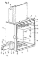
- the electronic module comprises 1 a box-shaped electronics housing part 10 with a floor, four side walls and one through the side walls limited opening 18 through which the housing interior 13 of the electronics housing part 10 is accessible.
- the opening is by a circumferential bearing surface 14 for a housing cover 2 limited to the outside of the side walls protruding lugs 17 can be fastened. So that the housing 10 can be tightly closed with the lid 2, the Contact surface 14 on a circumferential sealing ring 15.
- Farther has the electronics housing part 10 on a side wall a first connector part 11 and on a second side wall second outwardly projecting connector part 12.
- the connector parts 11, 12 are together in this first embodiment with the electronics housing part 10 in one piece as Injection molded part made of plastic.
- the first connector part 11 is provided for connecting an external control cable and has contact elements 21 which are partially in the housing part 10 are injected.
- the second plug part 12 has two power current conductors 23 and additionally four electrical connecting lines 22 on, which is also partially injected into the second connector part 12 are and protruding into the housing interior 13, have exposed connection sections.
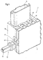
- Fig. 1 further It can be seen that they are in the housing interior 13 protruding connection sections of the power current conductors 23, connecting lines 22 and contact elements 21 in one Bent towards the opening 18 of the electronics housing part 10, so that all connection sections inside the housing are aligned parallel to each other.
- a relay 40 when installing the electronics module in the electronics housing part 10 inserted and fastened therein in such a way that the relay terminals 24 are parallel to the rest Connection sections 21,22,23 and the plug 5 in the direction extend the opening 18.
- a Printed circuit board 4 with components, not shown, in the Electronics housing part 10 used.
- the circuit board 4 is previously equipped with SMD components on one side and points Contact openings, for example in the form of through-metallized Holes on.
- connection sections the contact elements 21, the connecting lines 22, the power current conductor 23 and the relay terminals 24 through passed through the contact openings of the circuit board and then in the dip soldering process in one operation with the PCB soldered.
- An additional process step for Attachment of the relay on the circuit board after SMD soldering and before installing the circuit board is not necessary.
- the electronics housing part 10 closed with a lid 2 after the dip soldering.
- the cover 2 has a plurality of elastically resilient, protruding Tabs 45 as locking means, which when putting on of the lid 2 on the support area 14 with the lugs 17 of the Snap the electronics housing part 10 into place.
- the elastic Sealing ring 15 between cover 2 and support area 14 pinched so that the opening 18 of the electronics housing part 10 is sealed and the circuit board 4 completely is protected in the electronics housing part 10.
- the second from the outside of the electronics housing part 10 protruding connector part 12 has in this first embodiment a cone-like shape with a rectangular cross-sectional area.
- the plug part 12 has one of the housing 10 protruding bearing a circumferential sealing ring 16 Base 38 on, of which over a stepped edge 32 a cuboid End section 39 protrudes.
- the power current conductors 23 are in the base 38 completely surrounded by plastic.
- Contact sections 33 of the Power current conductors 23 occur at the stepped edge 32 out of the base 38 and lie on two outer edges of the End section 39 freely contactable.
- a pressure equalization channel 19 extends from the protruding end 31 into the interior of the housing 13th
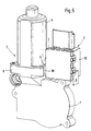
- the drive unit 3 is a window lifter with commutator motor and the specified one Electronics module 1 shown.
- the drive unit includes a Motor housing part 6, a brush part 8 and a gear housing 7.
- the electronics housing part 10 is connected to two T-grooves 55 pushed its underside onto the gear housing 7, wherein the second plug part 12 through an opening 9 in the brush part 8 inserted into the housing of the drive unit 3 becomes.
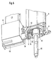
- the brush part 8 there is a brush holder 53, motor contacts 52 of the Electric motor and a mounted on the motor armature shaft 50 Ring magnet 51.
- the Hall IC device 28 detects the variable magnetic field of the rotating ring magnet 51 and leads one of the signal dependent on the magnetic field change via the connecting lines 22 of the control circuit arranged on the printed circuit board 4 to. Conversely, the control circuit controls the circuit board 4 via the relay 40 the power supply of the electric motor via the power current conductors 23 and motor contacts 52.
- relay 40 first solder on the circuit board 4 and the circuit board then with the assembled relay in the housing 10 of the electronics module.
- the Hall sensor element is not on the electronics housing part but in the housing of the drive unit, e.g. in the brush holder set.
- the Hall sensor element When pushing on the electronic module then contact protruding from the second connector part of the module Contact sections of the connecting lines, which from Corresponding mating contacts are led out of the second plug part the attached in the housing of the drive unit Hall sensor element.
- the second connector part 12 instructs in this embodiment Location of the electrical connection lines 22 magnetic flux conductors on, which is partially injected into the second connector part are and on the printed circuit board side and motor side with protruding End sections are provided.
- the magnetic flux conductors exist made of soft magnetic material with high permeability.
- the End sections on the motor side are in their contours the ring magnet adapted and by a narrow air gap from this spaced.
- the end sections of the magnetic flux conductors on the printed circuit board side end near the Hall IC device the circuit board, so that this is in the ring magnet, Air gap, magnetic flux conductors and Hall IC formed magnetic circuit induced magnetic field detected.
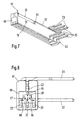
- second connector part 12 independent of the electronics housing part 10 manufacture.
- Figures 7 to 11 is a separate Part manufactured, finger-like connector part 12 with a first end portion 61 and a second end portion 62 shown.
- the plug part 12 is made of insulating material and with power current conductors 23 and connecting lines 22 Mistake.
- At the second end section 62 of the plug part 12 are designed as connector pins connecting sections Power current conductor 23 and connecting lines 22 made of the insulating material led out.
- the power current conductor 23 and connecting lines 22 are in depressions of the plug part 12 from the second end portion 62 to the opposite one out first end portion 61.
- the via bonding wires 65, 66, 67, 68 to the connecting lines 22 is electrically connected.
- an insulating Potting compound 71 applied, as best seen in Fig. 10 is.
- the casting compound can also be added to others Places are applied, the contact sections 33 of the power current conductor 23 through recesses 63 in the Insulation must remain accessible from the outside.
- the Hall IC component 28 against dirt, impurities and especially from coal dust in the brush holder 8 of an electric motor protected drive unit.
- Farther assigns the second connector part 12, as in FIGS. 7 and 10 is recognizable one from the second end portion 62 to a side opening near the contact portions 33 the power current conductor 23 extending pressure equalization channel 19 on.
- the plug part 12 can be manufactured for example be that a plastic preform 70 with recesses is manufactured, in which the power current conductor 23 and connecting lines 22 inserted as stamped metal parts become.
- the Hall IC device is at the first end portion 61 of the plug part inserted into the recess 69 and via bond wires 65, 66, 67 and 68 or other suitable Way electrically connected to the connecting lines 22.
- potting compound 71 or molding compound is placed on the pre-molded part 70 applied, at least the contact sections 33 the power conductor 23 and the pin-like connection sections the power conductor 23 and connecting lines 22 can be left out.
- the Hall IC component it is also possible initially solder the Hall IC component onto a lead frame, which Punching grid consists of punched metal sheets that are connected to one another via connecting webs, and then to overmold the lead frame with plastic, so that the Hall IC component is embedded in plastic.
- the connecting webs can then be cut out in the plastic be separated in a manner known per se, so that power conductors and connecting lines which are electrically separated from one another arise.
- the second Connector part 12 as a 3-D MID component (3-D Molds Interconnection Device). For this, an injected, three-dimensional Plastic base part with metallized conductor tracks provided which the power conductors and connecting lines form. Then a Hall IC device 28 contacted with the connecting lines and insulating Mold mass 71 applied to the base part 70.
- the second connector part 12 can be in one after its manufacture Injection mold are inserted and with the electronics housing part 10 are encapsulated. But it is also possible second connector part 12 in an opening in a side wall of the Use electronics housing part 10 and glue or to be fixed with locking devices on the side wall.
- the plug part 12 is arranged on the electronics housing part 10 in such a way that the second end portion 62 of the housing interior 13th is facing and the first end portion 61 with the Hall IC component protrudes from the electronics housing part 10 to the outside. Similar to the exemplary embodiment in FIG. 1 can the plug part 12 still with a stepped edge or be provided with a circumferential groove into which a sealing ring is inserted.
Landscapes
- Engineering & Computer Science (AREA)
- Power Engineering (AREA)
- Mechanical Engineering (AREA)
- Motor Or Generator Frames (AREA)
- Power-Operated Mechanisms For Wings (AREA)
Abstract
Description
Claims (19)
- Elektronikmodul für eine elektromotorisch betriebene Antriebseinheit, insbesondere für einen elektromotorischen Fensterheber eines Kraftfahrzeugs, umfassend ein am Gehäuse der Antriebseinheit festlegbares Elektronikgehäuseteil (10) mit einem daran angeordneten Steckerteil (11) und einer in eine Aufnahme (5) des Elektronikgehäuseteils (10) eingesetzten Leiterplatte (4) mit elektrischen und/oder elektronischen Bauelementen, welche Leiterplatte mit Kontaktelementen (21) des Steckerteils (11) und mit an dem Elektronikgehäuseteil (10) festgelegten Leistungsstromleitern (23) elektrisch kontaktiert ist, wobei die Leistungsstromleiter (23) mit von dem Elektronikgehäuseteil abstehenden Kontaktabschnitten (33) versehen sind, dadurch gekennzeichnet, daß das Elektronikgehäuseteil (10) als separates Gehäuse ausgebildet ist, welches einen mit einem Deckel (2) verschließbaren Gehäuseinnenraum (13) aufweist, daß die Leiterplatte (4) vollständig in dem Gehäuseinnenraum (13) angeordnet ist und daß ein zweites Steckerteil (12) an dem Elektronikgehäuseteil (10) angeordnet ist, durch welches wenigstens die Kontaktabschnitte (33) der Leistungsstromleiter (23) aus dem Elektronikgehäuseteil (10) herausgeführt sind.
- Elektronikmodul nach Anspruch 1, dadurch gekennzeichnet, daß das zweite Steckerteil (12) zusätzlich elektrische Anschlußleitungen (22) von elektrischen und/oder elektronischen Bauelementen (28) aufweist, welche Bauelemente außerhalb des Gehäuseinnenraumes (13) angeordnet sind.
- Elektronikmodul nach Anspruch 1, dadurch gekennzeichnet, daß das zweite Steckerteil (12) wenigstens einen Magnetflußleiter aufweist.
- Elektronikmodul nach Anspruch 2, dadurch gekennzeichnet, daß das zweite Steckerteil (12) als ein von dem Elektronikgehäuseteil (10) abstehender, einstückig mit dem Elekronikgehäuseteil (10) verbundener Zapfen ausgebildet ist, an dessen vom Gehäuse (10) abgewandten Ende (31) ein Hall-Sensor-Element (28), insbesondere ein Hall-IC-Bauelement, angeordnet ist, dessen elektrische Anschlüsse über die in dem Stekkerteil (12) vorgesehenen elektrischen Anschlußleitungen (22) mit der Leiterplatte (4) verbunden sind.
- Elektronikmodul nach Anspruch 4, dadurch gekennzeichnet, daß das Elektronikgehäuseteil (10) als Spritzgußteil mit angespritzten ersten und zweiten Steckerteil (11,12) gefertigt ist.
- Elektronikmodul nach Anspruch 2, dadurch gekennzeichnet, daß das zweite Steckerteil (12) unabhängig von dem Elektronikgehäuseteil (10) als separates Teil aus Isolierstoff mit zumindest teilweise in den Isolierstoff eingebetteten Leistungstromleitern (23) und Anschlußleitungen (22) für elektrische und/oder elektronische Bauelemente hergestellt ist, wobei in dem zweiten Steckerteil (12) wenigstens ein Hall-Sensor-Element (28), insbesondere ein Hall-IC-Bauelement, vollständig in Isolierstoff eingebettet ist und das zweite Steckerteil (12) an dem Elektronikgehäuseteil (10) angeordnet ist.
- Elektronikmodul nach Anspruch 6, dadurch gekennzeichnet, daß das zweite Steckerteil (12) mit einem ersten Endabschnitt (61) und einem diesen gegenüberliegenden zweiten Endabschnitt (62) ausgestaltet ist, daß an dem ersten Endabschnitt (61) das wenigstens eine vollständig in Isolierstoff eingebettete Hall-Sensor-Element (28) mit den Anschlußleitungen (22) elektrisch leitend verbunden ist und daß an dem zweiten Endabschnitt (62) Anschlußabschnitte der Leistungsstromleiter (23) und der Anschlußleitungen (22) aus dem Isolierstoff herausgeführt sind.
- Elektronikmodul nach Anspruch 7, dadurch gekennzeichnet, daß das zweite Steckerteil (12) als Isolierstoffspritzgußteil mit zumindest teilweise in die Isolierstoffmasse eingespritzten Leistungsstromleitern (23) und Anschlußleitungen (22) gefertigt ist und daß zumindest das Hall-Sensor-Element (28) mit einer isolierenden Vergußmasse (71) abgedeckt ist.
- Elektronikmodul nach Anspruch 7, dadurch gekennzeichnet, daß zumindest zwischen dem ersten Endabschnitt (61) und dem zweiten Endabschnitt (62) des zweiten Steckerteils (12) in dem Isolierstoff Aussparungen (63) vorgesehen sind, durch welche die Kontaktabschnitte (33) der Leistungsstromleiter (23) von außen kontaktierbar sind.
- Elektronikmodul nach Anspruch 7, dadurch gekennzeichnet, daß die Anschlußabschnitte der Leistungsstromleiter (23) und der Anschlußleitungen (22) an dem zweiten Endabschnitt (62) des zweiten Steckerteils (12) als in einer Richtung abstehende Kontaktstifte ausgebildet sind.
- Elektronikmodul nach einem der vorstehenden Ansprüche, dadurch gekennzeichnet, daß das Elektronikgehäuseteil (10) einen sich vom Gehäuseinnenraum (13) durch das zweite Stekkerteil (12) nach außen erstreckenden Druckausgleichskanal (19) aufweist.
- Elektronikmodul nach Anspruch 4 oder 6, dadurch gekennzeichnet, daß die leiterplattenseitigen Anschlußabschnitte der Kontaktelemente (21), Leistungsstromleiter (23) und elektrischen Anschlußleitungen (22) parallel zueinander verlaufend durch Kontaktöffnungen der Leiterplatte (4) hindurchgeführt und mit der Leiterplatte verlötet sind.
- Elektronikmodul nach Anspruch 12, dadurch gekennzeichnet, daß in dem Elektronikgehäuseteil (10) ein elektromagnetisches Relais (40) angeordnet ist, dessen Anschlüsse (24) parallel zu den leiterplattenseitigen Anschlußabschnitten der Kontaktelemente (21), Leistungsstromleiter (23) und elektrischen Anschlußleitungen (22) durch Kontaktöffnungen der Leiterplatte (4) hindurchgeführt und mit der Leiterplatte verlötet sind.
- Elektronikmodul nach Anspruch 12 oder 13, dadurch gekennzeichnet, daß die Leiterplatte (4) im Gehäuseinnenraum (13) des Elektronikgehäuseteils dem Deckel (2) unmittelbar gegenüberliegend angeordnet ist.
- Elektronikmodul nach einem der Ansprüche 12 bis 14, dadurch gekennzeichnet, daß die durch die Kontaktöffnungen der Leiterplatte (4) hindurchgeführten Anschlußabschnitte im Tauchlotverfahren mit der Leiterplatte verlötet sind.
- Elektronikmodul nach einem der vorstehenden Ansprüche, dadurch gekennzeichnet, daß das Elektronikgehäuseteil (10) im Auflagebereich (14) des Deckels (2) eine umlaufende Dichtung (15) aufweist.
- Elektronikmodul nach Anspruch 1, dadurch gekennzeichnet, daß das Elektronikgehäuseteil (10) des Elektronikmoduls am Gehäuse (3) einer elektromotorisch betriebenen Antriebseinheit festlegbar ist und mit dem zweiten Steckerteil (12) in eine entsprechend ausgebildete Öffnung (9) des Gehäuses (3) der Antriebseinheit derart einführbar ist, daß die Leistungsstromleiter (23) mit im Gehäuse der Antriebseinheit angeordneten Motorkontakten (52) des Gebriebemotors kontaktieren.
- Elektronikmodul nach Anspruch 17, dadurch gekennzeichnet, daß das zweite Steckerteil (12) an seiner Umfangsfläche einen umlaufenden Dichtungsring (16) aufweist und daß die im Gehäuse (3) der Antriebseinheit zur Einführung des zweiten Steckerteils (12) ausgebildete Öffnung (9) bei der Festlegung des Elektronikmoduls (1) an der Antriebseinheit durch den Dichtungsring (16) des zweiten Steckerteils (12) dicht verschließbar ist.
- Elektronikmodul nach Anspruch 18, dadurch gekennzeichnet, daß ein an dem abstehenden Ende (31) des zweiten Stekkerteils (12) vorgesehenes Hall-Sensor-Element (28) bei auf die Antriebseinheit aufgestecktem Elektronikmodul das Magnetfeld eines auf der Motorankerwelle (50) des Get:riebemotors angeordneten Ringmagneten (51) erfaßt.
Applications Claiming Priority (5)
| Application Number | Priority Date | Filing Date | Title |
|---|---|---|---|
| DE19804490 | 1998-02-05 | ||
| DE19804490 | 1998-02-05 | ||
| DE19851455A DE19851455A1 (de) | 1998-02-05 | 1998-11-09 | Elektronikmodul für eine elektromotorisch betriebene Antriebseinheit |
| DE19851455 | 1998-11-09 | ||
| PCT/DE1998/003719 WO1999040285A1 (de) | 1998-02-05 | 1998-12-17 | Elektronikmodul für eine elektromotorisch betriebene antriebseinheit |
Publications (2)
| Publication Number | Publication Date |
|---|---|
| EP1000215A1 EP1000215A1 (de) | 2000-05-17 |
| EP1000215B1 true EP1000215B1 (de) | 2003-05-07 |
Family
ID=26043617
Family Applications (1)
| Application Number | Title | Priority Date | Filing Date |
|---|---|---|---|
| EP98966781A Expired - Lifetime EP1000215B1 (de) | 1998-02-05 | 1998-12-17 | Elektronikmodul für eine elektromotorisch betriebene antriebseinheit |
Country Status (4)
| Country | Link |
|---|---|
| US (1) | US6317332B1 (de) |
| EP (1) | EP1000215B1 (de) |
| BR (1) | BR9807925A (de) |
| WO (1) | WO1999040285A1 (de) |
Cited By (2)
| Publication number | Priority date | Publication date | Assignee | Title |
|---|---|---|---|---|
| DE102008053573A1 (de) * | 2008-10-15 | 2010-04-22 | Bühler Motor GmbH | Stellantrieb zur Betätigung einer linearen Einheit |
| FR3148681A1 (fr) * | 2023-05-12 | 2024-11-15 | Psa Automobiles Sa | Dispositif de telecodage de boitier electronique programmable |
Families Citing this family (57)
| Publication number | Priority date | Publication date | Assignee | Title |
|---|---|---|---|---|
| DE10004059A1 (de) * | 2000-02-01 | 2001-11-08 | Buhler Motor Gmbh | Mehrphasen-Motor |
| FR2807877B1 (fr) * | 2000-04-14 | 2002-10-31 | Meritor Light Vehicle Sys Ltd | Connecteur a concentrateur de flux pour moteur electrique |
| DE10020017B4 (de) * | 2000-04-22 | 2010-04-22 | Brose Fahrzeugteile Gmbh & Co. Kommanditgesellschaft, Coburg | Elektromechanische Antriebsvorrichtung |
| DE10020018A1 (de) * | 2000-04-22 | 2001-11-08 | Brose Fahrzeugteile | Elektromechanische Antriebsvorrichtung |
| DE10022968A1 (de) | 2000-05-11 | 2001-11-15 | Bosch Gmbh Robert | Elektronikgerät |
| DE10129234A1 (de) * | 2000-06-21 | 2002-02-07 | Bosch Gmbh Robert | Elektrische Antriebseinheit |
| US6548934B1 (en) * | 2000-07-31 | 2003-04-15 | Valeo Electrical Systems, Inc. | Brush holder lead frame with integral electrical terminals |
| DE10130118C2 (de) * | 2001-06-22 | 2003-05-08 | Minebea Co Ltd | Trägervorrichtung für einen Elektromotor, insbesondere für einen elektronisch kommunitierten Gleichstrommotor |
| DE10141244A1 (de) * | 2001-08-23 | 2003-03-13 | Brose Fahrzeugteile | Mechanische Schnittstellenvorrichtung |
| DE10207004A1 (de) * | 2002-02-19 | 2003-08-28 | Bosch Gmbh Robert | Antriebsvorrichtung |
| FR2840123B1 (fr) * | 2002-05-22 | 2004-08-27 | Meritor Light Vehicle Sys Ltd | Dispositif de motoreduction et connecteur de motoreducteur |
| DE10248977A1 (de) * | 2002-10-21 | 2004-06-03 | Siemens Ag | Anschlussstück für einen Elektromotor |
| DE10318062A1 (de) * | 2003-04-17 | 2004-11-11 | Robert Bosch Gmbh | Getriebe-Antriebseinheit mit Elektronik-Schnittstelle |
| ITPD20030036U1 (it) * | 2003-05-13 | 2004-11-14 | Nuova S M E Spa | Struttura di motore o motoriduttore elettrico |
| US7038337B2 (en) * | 2003-05-20 | 2006-05-02 | Siemens Vdo Automotive Corporation | EMI suppression in permanent magnet DC motors having PCB outside motor in connector and overmolded |
| DE10331238A1 (de) * | 2003-07-10 | 2005-02-03 | Robert Bosch Gmbh | Elektromotor mit mehrteiliger Leiterplatte |
| DE10342219A1 (de) * | 2003-09-11 | 2005-04-21 | K Tec Kunststoffverarbeitung G | Topf- oder becherförmiger Träger |
| ITTO20030754A1 (it) * | 2003-09-29 | 2005-03-30 | Gate Srl | Unita' elettronica di controllo, in particolare unita' |
| DE10352079A1 (de) * | 2003-11-08 | 2005-06-02 | Robert Bosch Gmbh | Elektromotor, sowie Verfahren zur Herstellung eines solchen |
| ITPD20040038U1 (it) * | 2004-04-29 | 2004-07-29 | Nuova S M E Spa | Struttura di motore elettrico |
| FR2875650B1 (fr) * | 2004-09-21 | 2007-07-27 | Arvinmeritor Light Vehicle Sys | Procede d'assemblage d'un boitier electronique avec un carter de moteur electrique |
| US20080289309A1 (en) * | 2005-02-09 | 2008-11-27 | Gust Jackie R | Mower with Hybrid Prime Mover Having Fuel Cell, Brushless Electric Motors for Driving Cutting Units, and Electric/Hydraulic Actuator for Lift and Lower System |
| ITBO20050236A1 (it) * | 2005-04-14 | 2006-10-15 | Selta S R L | Modulo da innesto per l'alimentazione e la regolazione di un motore elettrico |
| DE602005016380D1 (de) * | 2005-06-09 | 2009-10-15 | Antolin Grupo Ing Sa | Magnetischer Flussleiter für elektronisch geregelte Motoren, Motor mit diesem Magnetflussleiter und Antriebseinheit für mechanische Systeme |
| CA2610798A1 (en) * | 2005-06-10 | 2006-12-14 | Magna Closures Inc. | Motor drive assembly |
| JP5006713B2 (ja) * | 2007-06-28 | 2012-08-22 | 株式会社ミツバ | ブラシ付き電動モータ |
| JP5106086B2 (ja) * | 2007-12-25 | 2012-12-26 | 株式会社不二工機 | コイル装置のリード線引出し構造 |
| DE202008000440U1 (de) * | 2008-01-11 | 2008-04-03 | Sma Technologie Ag | Wechselrichter |
| WO2009124319A2 (en) * | 2008-04-04 | 2009-10-08 | Taps Manufacturing, Inc. | Low harmonic rectifier circuit |
| KR101567061B1 (ko) * | 2008-07-28 | 2015-11-09 | 엘지이노텍 주식회사 | 스텝 액츄에이터와 인쇄회로기판용 케이스의 결합 구조 |
| EP2164314B1 (de) * | 2008-09-16 | 2014-11-19 | Grundfos Management A/S | Klemmenkasten zum elektrischen Anschluss an einen Elektromotor |
| EP2164153B1 (de) * | 2008-09-16 | 2015-03-11 | Grundfos Management A/S | Klemmenkasten zum elektrischen Anschluss an einen Elektromotor |
| DE202009014865U1 (de) * | 2009-12-16 | 2011-04-28 | Bucyrus Europe Gmbh | Steckmodul für Steuergeräte von mobilen Arbeitsmaschinen |
| CN102118078A (zh) * | 2009-12-30 | 2011-07-06 | 德昌电机(深圳)有限公司 | 电机驱动组件 |
| DE102010002511A1 (de) * | 2010-03-02 | 2011-09-08 | Robert Bosch Gmbh | Verstellantrieb, insbesondere Fensterheberantrieb |
| CN102147003A (zh) * | 2010-06-30 | 2011-08-10 | 上海实业交通电器有限公司 | 一种汽车摇窗电机减速箱保护盖板联接结构 |
| DE102010025689B4 (de) * | 2010-06-30 | 2022-03-24 | Valeo Wischersysteme Gmbh | Antriebseinheit für eine Scheibenwischvorrichtung in einem Fahrzeug und Gehäuse für eine Antriebseinheit |
| KR101672847B1 (ko) * | 2010-11-05 | 2016-11-16 | 아스모 가부시키가이샤 | 모터 |
| FR2976420B1 (fr) * | 2011-06-07 | 2013-07-12 | Converteam Technology Ltd | Systeme de refroidissement a eau deionisee pour equipement electrique |
| DE102011055349B3 (de) | 2011-11-15 | 2013-01-17 | Brose Fahrzeugteile Gmbh & Co. Kommanditgesellschaft, Hallstadt | Gehäuse und Bausatz für eine Steuerungsvorrichtung |
| JP5942580B2 (ja) * | 2012-05-15 | 2016-06-29 | マックス株式会社 | 電動工具 |
| EP2690412B1 (de) | 2012-07-25 | 2018-04-18 | Baumer Electric AG | Sensor |
| EP2728985B1 (de) | 2012-11-02 | 2018-01-31 | Siemens Schweiz AG | Stellantrieb mit elektrischer Steckverbindung |
| JP6224091B2 (ja) * | 2013-04-30 | 2017-11-01 | 株式会社ミツバ | モータ装置 |
| DE102013226205A1 (de) * | 2013-12-17 | 2015-06-18 | Conti Temic Microelectronic Gmbh | Einschubmodul für eine Motoreinheit |
| DE102013226204A1 (de) * | 2013-12-17 | 2015-06-18 | Conti Temic Microelectronic Gmbh | Einschubmodul für eine Motoreinheit |
| ITPD20140163A1 (it) * | 2014-06-24 | 2015-12-24 | Amer Spa | Struttura perfezionata di motore brushless |
| CN105490453B (zh) * | 2014-09-19 | 2019-12-03 | 德昌电机(深圳)有限公司 | 驱动装置 |
| DE102015205518A1 (de) * | 2015-03-26 | 2016-09-29 | Robert Bosch Gmbh | Elektronikgehäuse mit ein- und ausfahrbarem elektrischen Steckverbinder |
| US10483825B2 (en) * | 2015-06-24 | 2019-11-19 | Cts Corporation | Rotary actuator |
| FR3072837B1 (fr) * | 2017-10-20 | 2021-01-22 | Bernard Controls | Servomoteur pour vanne ou vantelle industrielle avec carte de raccordement et connecteur |
| JP7127507B2 (ja) * | 2018-11-20 | 2022-08-30 | 住友電装株式会社 | コネクタ |
| DE102019102536A1 (de) * | 2019-02-01 | 2020-08-06 | Nidec Motors & Actuators (Germany) Gmbh | Verstellantrieb aufweisend eine Bürstenkartenanordnung mit integrierter Leiterplatte |
| CN210246355U (zh) * | 2019-08-01 | 2020-04-03 | 深圳雾芯科技有限公司 | 一种电力供应装置 |
| DE102019120913A1 (de) * | 2019-08-02 | 2021-02-04 | Schaeffler Technologies AG & Co. KG | Elektromotor |
| DE102019120912A1 (de) | 2019-08-02 | 2021-02-04 | Schaeffler Technologies AG & Co. KG | Elektromotor |
| CN112203460B (zh) * | 2020-10-23 | 2021-10-08 | 湖南超川电子科技有限公司 | 一种伺服驱动器短路保护装置 |
Family Cites Families (7)
| Publication number | Priority date | Publication date | Assignee | Title |
|---|---|---|---|---|
| EP0538495B1 (de) * | 1991-07-31 | 1994-07-27 | Siemens Aktiengesellschaft | Motorischer Fensterheberantrieb für ein Kraftfahrzeug |
| DE4225496A1 (de) * | 1992-08-01 | 1994-02-03 | Brose Fahrzeugteile | Elektrische Antriebseinheit für Verstellsysteme in Kraftfahrzeugen |
| EP0618659B2 (de) | 1993-03-31 | 2001-07-04 | Siemens Aktiengesellschaft | Kommutatormotor-Getriebe-Antriebseinheit, insbesondere Kraftfahrzeug-Fensterheberantrieb |
| US5770902A (en) * | 1995-11-02 | 1998-06-23 | Globe Motors | Motor termination board |
| US5777410A (en) * | 1995-12-04 | 1998-07-07 | Asmo Co., Ltd. | Motor actuator and method of making the same |
| DE19746518A1 (de) * | 1997-10-22 | 1999-04-29 | Bosch Gmbh Robert | Einschubmodul für einen elektromotorischen Fensterheber |
| DE19839333C1 (de) * | 1998-08-28 | 2000-01-05 | Kostal Leopold Gmbh & Co Kg | Antriebseinrichtung |
-
1998
- 1998-12-17 US US09/402,566 patent/US6317332B1/en not_active Expired - Fee Related
- 1998-12-17 EP EP98966781A patent/EP1000215B1/de not_active Expired - Lifetime
- 1998-12-17 BR BR9807925-5A patent/BR9807925A/pt not_active IP Right Cessation
- 1998-12-17 WO PCT/DE1998/003719 patent/WO1999040285A1/de not_active Ceased
Cited By (3)
| Publication number | Priority date | Publication date | Assignee | Title |
|---|---|---|---|---|
| DE102008053573A1 (de) * | 2008-10-15 | 2010-04-22 | Bühler Motor GmbH | Stellantrieb zur Betätigung einer linearen Einheit |
| DE102008053573B4 (de) | 2008-10-15 | 2022-06-15 | Bühler Motor GmbH | Stellantrieb zur Betätigung einer linearen Einheit |
| FR3148681A1 (fr) * | 2023-05-12 | 2024-11-15 | Psa Automobiles Sa | Dispositif de telecodage de boitier electronique programmable |
Also Published As
| Publication number | Publication date |
|---|---|
| US6317332B1 (en) | 2001-11-13 |
| WO1999040285A1 (de) | 1999-08-12 |
| BR9807925A (pt) | 2000-02-22 |
| EP1000215A1 (de) | 2000-05-17 |
Similar Documents
| Publication | Publication Date | Title |
|---|---|---|
| EP1000215B1 (de) | Elektronikmodul für eine elektromotorisch betriebene antriebseinheit | |
| DE19851455A1 (de) | Elektronikmodul für eine elektromotorisch betriebene Antriebseinheit | |
| EP0993696B1 (de) | Antriebsvorrichtung, insbesondere zum verstellen eines schiebedachs eines fahrzeugs | |
| EP1230107B1 (de) | Steuergerät für ein kraftfahrzeug | |
| EP1622241B1 (de) | Elektromotor mit hohem Schutzgrad gegen das Eindringen von Fremdkörpern und Nässe | |
| EP0937261B1 (de) | Sensoreinrichtung | |
| DE10006320A1 (de) | Elektrische Antriebseinheit aus Elektromotor und Elektronikmodul | |
| AT503687B1 (de) | Steuergerät mit einem stirnseitig kontaktierten schaltungsträger | |
| EP1070380B1 (de) | Elektromotorischer antrieb | |
| US20090190315A1 (en) | Control unit for controlling an electromotive drive unit | |
| WO1998040751A1 (de) | Motor mit drehzahlabgriff über einen hall-sensor | |
| DE10019512A1 (de) | Motorgehäuse und Poltopf, insbesondere für Fensterheber- oder Schiebedachmotoren | |
| DE102012218847A1 (de) | Anschlusselement für eine Antriebsanordnung sowie eine Antriebsanordnung mit einem Anschlussteil | |
| DE102009020075B4 (de) | Elektromotorische Antriebseinheit für Kraftfahrzeug-Stellantriebe | |
| WO2007054395A1 (de) | Getriebe-antriebseinheit mit elektronik-einsteckmodul | |
| DE10130117A1 (de) | Gehäusedeckel für einen Elektromotor, insbesondere für einen elektronisch kommutierten Gleichstrommotor | |
| EP1546529B1 (de) | Deckel | |
| EP1282345B1 (de) | Gehäuse zur Aufnahme einer Leiterplatte mit elektronischen Bauteilen in Fahrzeugen | |
| DE19816216C2 (de) | Elektrischer Stecker und Steckverbindung | |
| DE10229606B4 (de) | Verfahren zur Herstellung elektrischer Kontakierungsbereiche an einem Stellantrieb und Stellantrieb | |
| EP1734621A2 (de) | Anordnung und Verfahren zum elektrischen Anschluss einer elektronischen Schaltung in einem Gehäuse | |
| DE19807718C2 (de) | Elektronikbaugruppe | |
| EP1247323A1 (de) | Elektrisch betrieber motor | |
| DE10161102A1 (de) | Leitungs-Steckverbindung für elektrisches Steuergerät sowie Herstellungsverfahren | |
| DE4227062C1 (de) | Dichtende Anschlußplatte für einen Elektromotor |
Legal Events
| Date | Code | Title | Description |
|---|---|---|---|
| PUAI | Public reference made under article 153(3) epc to a published international application that has entered the european phase |
Free format text: ORIGINAL CODE: 0009012 |
|
| 17P | Request for examination filed |
Effective date: 20000214 |
|
| AK | Designated contracting states |
Kind code of ref document: A1 Designated state(s): DE FR GB IT SE |
|
| GRAH | Despatch of communication of intention to grant a patent |
Free format text: ORIGINAL CODE: EPIDOS IGRA |
|
| GRAH | Despatch of communication of intention to grant a patent |
Free format text: ORIGINAL CODE: EPIDOS IGRA |
|
| GRAA | (expected) grant |
Free format text: ORIGINAL CODE: 0009210 |
|
| AK | Designated contracting states |
Designated state(s): DE FR GB IT SE |
|
| REG | Reference to a national code |
Ref country code: GB Ref legal event code: FG4D Free format text: NOT ENGLISH |
|
| REF | Corresponds to: |
Ref document number: 59808289 Country of ref document: DE Date of ref document: 20030612 Kind code of ref document: P |
|
| REG | Reference to a national code |
Ref country code: SE Ref legal event code: TRGR |
|
| GBT | Gb: translation of ep patent filed (gb section 77(6)(a)/1977) | ||
| ET | Fr: translation filed | ||
| PLBE | No opposition filed within time limit |
Free format text: ORIGINAL CODE: 0009261 |
|
| STAA | Information on the status of an ep patent application or granted ep patent |
Free format text: STATUS: NO OPPOSITION FILED WITHIN TIME LIMIT |
|
| 26N | No opposition filed |
Effective date: 20040210 |
|
| PGFP | Annual fee paid to national office [announced via postgrant information from national office to epo] |
Ref country code: IT Payment date: 20071222 Year of fee payment: 10 |
|
| PGFP | Annual fee paid to national office [announced via postgrant information from national office to epo] |
Ref country code: SE Payment date: 20071220 Year of fee payment: 10 |
|
| PGFP | Annual fee paid to national office [announced via postgrant information from national office to epo] |
Ref country code: GB Payment date: 20071220 Year of fee payment: 10 |
|
| EUG | Se: european patent has lapsed | ||
| GBPC | Gb: european patent ceased through non-payment of renewal fee |
Effective date: 20081217 |
|
| PG25 | Lapsed in a contracting state [announced via postgrant information from national office to epo] |
Ref country code: GB Free format text: LAPSE BECAUSE OF NON-PAYMENT OF DUE FEES Effective date: 20081217 |
|
| PG25 | Lapsed in a contracting state [announced via postgrant information from national office to epo] |
Ref country code: SE Free format text: LAPSE BECAUSE OF NON-PAYMENT OF DUE FEES Effective date: 20081218 |
|
| REG | Reference to a national code |
Ref country code: DE Ref legal event code: R084 Ref document number: 59808289 Country of ref document: DE Effective date: 20130617 |
|
| PG25 | Lapsed in a contracting state [announced via postgrant information from national office to epo] |
Ref country code: IT Free format text: LAPSE BECAUSE OF NON-PAYMENT OF DUE FEES Effective date: 20081217 |
|
| PGFP | Annual fee paid to national office [announced via postgrant information from national office to epo] |
Ref country code: FR Payment date: 20131213 Year of fee payment: 16 |
|
| PGFP | Annual fee paid to national office [announced via postgrant information from national office to epo] |
Ref country code: DE Payment date: 20140221 Year of fee payment: 16 |
|
| REG | Reference to a national code |
Ref country code: DE Ref legal event code: R119 Ref document number: 59808289 Country of ref document: DE |
|
| REG | Reference to a national code |
Ref country code: FR Ref legal event code: ST Effective date: 20150831 |
|
| PG25 | Lapsed in a contracting state [announced via postgrant information from national office to epo] |
Ref country code: DE Free format text: LAPSE BECAUSE OF NON-PAYMENT OF DUE FEES Effective date: 20150701 |
|
| PG25 | Lapsed in a contracting state [announced via postgrant information from national office to epo] |
Ref country code: FR Free format text: LAPSE BECAUSE OF NON-PAYMENT OF DUE FEES Effective date: 20141231 |