EP1000228B1 - Valve de reaspiration des gaz du carter pour moteur a combustion interne - Google Patents
Valve de reaspiration des gaz du carter pour moteur a combustion interne Download PDFInfo
- Publication number
- EP1000228B1 EP1000228B1 EP98936331A EP98936331A EP1000228B1 EP 1000228 B1 EP1000228 B1 EP 1000228B1 EP 98936331 A EP98936331 A EP 98936331A EP 98936331 A EP98936331 A EP 98936331A EP 1000228 B1 EP1000228 B1 EP 1000228B1
- Authority
- EP
- European Patent Office
- Prior art keywords
- crankcase
- internal combustion
- combustion engine
- duct
- valve
- Prior art date
- Legal status (The legal status is an assumption and is not a legal conclusion. Google has not performed a legal analysis and makes no representation as to the accuracy of the status listed.)
- Expired - Lifetime
Links
- 238000002485 combustion reaction Methods 0.000 title claims abstract description 40
- 239000007789 gas Substances 0.000 title abstract description 33
- 238000009423 ventilation Methods 0.000 claims description 27
- 230000006835 compression Effects 0.000 claims description 3
- 238000007906 compression Methods 0.000 claims description 3
- 238000003466 welding Methods 0.000 claims description 3
- 239000012528 membrane Substances 0.000 abstract description 14
- 238000009434 installation Methods 0.000 description 9
- 230000001419 dependent effect Effects 0.000 description 2
- 239000003344 environmental pollutant Substances 0.000 description 2
- 231100000719 pollutant Toxicity 0.000 description 2
- 238000004026 adhesive bonding Methods 0.000 description 1
- 238000010276 construction Methods 0.000 description 1
- 229930195733 hydrocarbon Natural products 0.000 description 1
- 150000002430 hydrocarbons Chemical class 0.000 description 1
- 238000000034 method Methods 0.000 description 1
- 230000004048 modification Effects 0.000 description 1
- 238000012986 modification Methods 0.000 description 1
- 238000004064 recycling Methods 0.000 description 1
- 238000000926 separation method Methods 0.000 description 1
- 238000011144 upstream manufacturing Methods 0.000 description 1
Images


Classifications
-
- F—MECHANICAL ENGINEERING; LIGHTING; HEATING; WEAPONS; BLASTING
- F01—MACHINES OR ENGINES IN GENERAL; ENGINE PLANTS IN GENERAL; STEAM ENGINES
- F01M—LUBRICATING OF MACHINES OR ENGINES IN GENERAL; LUBRICATING INTERNAL COMBUSTION ENGINES; CRANKCASE VENTILATING
- F01M13/00—Crankcase ventilating or breathing
- F01M13/02—Crankcase ventilating or breathing by means of additional source of positive or negative pressure
- F01M13/021—Crankcase ventilating or breathing by means of additional source of positive or negative pressure of negative pressure
- F01M13/022—Crankcase ventilating or breathing by means of additional source of positive or negative pressure of negative pressure using engine inlet suction
- F01M13/023—Control valves in suction conduit
-
- F—MECHANICAL ENGINEERING; LIGHTING; HEATING; WEAPONS; BLASTING
- F01—MACHINES OR ENGINES IN GENERAL; ENGINE PLANTS IN GENERAL; STEAM ENGINES
- F01M—LUBRICATING OF MACHINES OR ENGINES IN GENERAL; LUBRICATING INTERNAL COMBUSTION ENGINES; CRANKCASE VENTILATING
- F01M13/00—Crankcase ventilating or breathing
- F01M13/02—Crankcase ventilating or breathing by means of additional source of positive or negative pressure
Definitions
- the invention relates to a crankcase ventilation valve for an internal combustion engine a valve housing, a gas inflow channel connected to the interior of the crankcase, one connected to an air intake duct of the internal combustion engine Gas outflow channel and a membrane, which the valve housing in a crankcase side divides inner and outer chamber and has a vent valve plate, the membrane with the vent valve plate depending on the pressure difference between the either chamber opens or closes the gas outflow channel according to the Preamble of claim 1.
- DE 44 06 986 A1 proposes a generic crankcase ventilation valve in front.
- a hole is provided in the cover of the valve housing, which the outer chamber on a side of the membrane facing away from the crankcase with the Ambient pressure connects.
- the gas discharge channel is arranged on the crankcase side, opposite the chamber with ambient pressure and thus a complicated gas duct routing out of the vent valve through the Crankcase to the air intake duct of the internal combustion engine is required.
- the present invention is therefore based on the object of a crankcase ventilation valve to provide the above type, the above Disadvantages are overcome and which is universal regardless of the installation position the internal combustion engine can be used.
- the invention provides that the outer chamber of the valve housing connected to the gas inflow duct and also a ventilation duct on the crankcase side is formed, which with the inner crankcase side chamber of the valve housing connects an ambient pressure.
- Valve housing is formed in two parts, with a base frame open on one side and a cover in which the gas outflow channel is integrated, the base frame rotationally symmetrical and the lid at least at the junction with the Base frame is rotationally symmetrical.
- the cover with the gas discharge channel is connected to the base frame in a position during assembly that the Gas outflow channel points in a desired direction, depending on the installation position of the internal combustion engine. Additional adapter hose connections between the vent valve and Air intake duct of the internal combustion engine for different installation positions of the internal combustion engine can possibly be omitted and the gas outflow channel is always optimal Direction to the air intake duct of the internal combustion engine aligned or alignable.
- a simple and inexpensive assembly results from the fact that the base frame and optionally additionally the ventilation duct is formed integrally with the crankcase is.
- the membrane is against the pressure in the crankcase-side inner chamber biased by a spring. This is a predetermined pressure for the crankcase can be set by means of the spring force.
- the spring is a compression spring, especially a coil spring, and in the outer chamber is arranged.
- the ventilation duct is expediently integral with the crankcase or a hood of the crankcase.
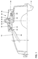
- Hood 13 includes a base frame 14 and a cover 16, which together Form valve housing 14, 16.
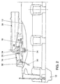
- a membrane 18 is arranged in the valve housing 14, 16, which is supported on a seat 20 and the valve housing 14, 16 in two Chambers 22 and 24, namely a lower chamber 22 and an upper chamber 24, share.
- the lower chamber 22 is arranged on the crankcase side, and the upper chamber 24 opposite on a side of the valve housing 14 facing away from the crankcase 12, 16 trained.
- Under crankcase 12, the entirety of one is the running gear understood cylinder crankcase and a cylinder head placed thereon.
- the seat 20 of the membrane 18 and the base frame 14 of the valve housing are integral trained with the hood 13.
- the cover 16 which can be placed on the base frame 14 comprises additionally a gas discharge channel 28 with a connector 30 for connection to one Air intake duct, not shown, of the internal combustion engine. This way the top one Chamber 24 connected to the air intake duct of the internal combustion engine. So be the crankcase gases entering the upper chamber 24 via a gas inflow channel 32 38 returned to the combustion process of the internal combustion engine and escape not in the area.
- a vent valve plate 34 is arranged such that this a reciprocating movement of the membrane 18 optionally opens the gas outflow channel 28 or closes.
- the lower chamber 22 is on the crankcase side via an ventilation duct 26 connected to the environment. In this way there is in the lower chamber 22 always the ambient pressure. Since the upper chamber 24 with the air intake duct Internal combustion engine is connected, prevails between the upper chamber 24 and the lower chamber 22 always a pressure difference, which is the pressure difference between the air intake duct corresponds to the internal combustion engine and the environment. With a negative pressure in the upper chamber 24, ie in the air intake duct, the membrane 18 is shown in the figures 1 and 2 pushed up, and the vent valve plate 34 closes the gas discharge channel 28.
- crankcase ventilation valve 10 This automatically prevents the vacuum from getting too deep into the crankcase 12 continues and, if necessary, air through the crankshaft seal into the crankcase 12 is sucked in. On the other hand, there is a certain negative pressure on the crankcase ventilation valve 10 is desirable so that the crankcase gases 38 are extracted accordingly become.
- a spring 36 is provided, which is designed as a spiral and compression spring 36 and is arranged in the upper chamber 24.
- This spring 36 acts on the membrane 18 against the ambient pressure in the opening direction of the vent valve plate 34 with a Force, so that the vent valve plate 34, the gas discharge channel 28 only at one of the Spring tension closes predetermined pressure difference between the chambers 22 and 24.
- the crankcase 12 is inserted into the air intake duct vented the internal combustion engine.
- a maximum negative pressure is set in the air intake duct of the internal combustion engine until to which there is a vent. If this negative pressure or the pressure difference increases between Air intake duct and ambient pressure above a predetermined by the spring 36 Value, the external overpressure closes via the membrane 18 and the vent valve plate 34 the gas outflow channel 28.
- FIGS. 1 and 2 the gas outflow channel 28 is from the vent valve plate 34 closed.
- Figure 3 shows the state when open Gas outflow channel 28.
- the spring force is sufficiently large or the negative pressure in the upper chamber 24 sufficiently small and the crankcase gases 38 flow out of the Crankcase 12 out over the hood 13 into the upper chamber 22 and over the Gas outflow duct 28 and the connector 30 in the air intake duct of the internal combustion engine, a slight negative pressure in the air intake duct may support this process.
- the connector 30 for connecting to the air intake duct Internal combustion engine must be aligned in a correspondingly different direction.
- the cover 16 on its circumference, which is in contact with the base frame 14 comes, and the base frame 14 is rotationally symmetrical. In this way the cover 14 can be placed on the base frame 14 in any angular position and connected to it so that the nozzle 30 at any angle Can be aligned 360 degrees around the lid.
- the connection is preferably made by friction welding, however, other solutions are also available, for example gluing, screwing or Ultrasonic welding, conceivable.
- crankcase ventilation valve 10 A special feature of the crankcase ventilation valve 10 is that the Atmospheric connection on a rear side of the membrane 18, that is to say from the “inside” or on the crankcase side, takes place via an integral, for example in the hood 13 of the crankcase 12, trained channel 26.
- Oil separation takes place, for example, in a direction upstream of the gas inflow channel 32 arranged, not shown labyrinth in the hood 13 and the Crankcase 12. If there is oil with the crankcase gases 38 in the upper chamber 24 occurs, this can be in the chamber 24, for example at the boundary delimited by the cover 16 Side, are separated and then again via the gas inflow channels 32 drain back into the crankcase 12.
Landscapes
- Engineering & Computer Science (AREA)
- Mechanical Engineering (AREA)
- General Engineering & Computer Science (AREA)
- Lubrication Details And Ventilation Of Internal Combustion Engines (AREA)
- Lubrication Of Internal Combustion Engines (AREA)
Claims (8)
- Moteur à combustion interne avec une valve de réaspiration des gaz du carter (10) et un corps de valve (14, 16), un conduit d'arrivée des gaz (32) relié avec l'espace intérieur du carter (12), un conduit d'évacuation des gaz (28) relié à un conduit d'admission d'air du moteur à combustion interne et une membrane (18), laquelle divise le corps de valve (14, 16) en une chambre (22, 24) située à l'intérieur par rapport au carter (12) et une autre situés à l'extérieur et présente une tête de soupape de réaspiration des gaz (34), la membrane (18) munie de la tête de soupape de réaspiration des gaz (34) ouvrant ou fermant alternativement le conduit d'évacuation des gaz (28) en fonction de la différence de pression entre les deux chambres (22, 24), caractérisé en ce que la chambre extérieure (24) du corps de valve (14, 16) est relié avec le conduit d'arrivée des gaz (32) et un conduit de ventilation (26) disposé en direction du carter est en outre réalisé, lequel relie la chambre intérieure (22) du corps de valve (14, 16) avec une pression environnante.
- Moteur à combustion interne avec une valve de réaspiration des gaz du carter (10) selon la revendication 1, caractérisé en ce que le corps de valve est divisé en deux parties avec un cadre de base (14) ouvert d'un côté et un couvercle (16) dans lequel est intégré le conduit d'évacuation des gaz (28).
- Moteur à combustion interne avec une valve de réaspiration des gaz du carter (10) selon la revendication 2, caractérisé en ce que le cadre de base (14) est réalisé à symétrie de révolution et le couvercle (16) est réalisé à symétrie de révolution au moins à un point de jonction avec le cadre de base (14).
- Moteur à combustion interne avec une valve de réaspiration des gaz du carter (10) selon la revendication 2 ou 3, caractérisé en ce que le couvercle (16) et le cadre de base (14) sont reliés ensemble par soudage par friction.
- Moteur à combustion interne avec une valve de réaspiration des gaz du carter (10) selon l'une des revendications 2 à 4, caractérisé en ce que le cadre de base (14) fait partie intégrante du carter (12) ou d'un capot (13) du carter (12).
- Moteur à combustion interne avec une valve de réaspiration des gaz du carter (10) selon l'une des revendications précédentes, caractérisé en ce que le conduit de ventilation (26) fait partie intégrante du carter (12) ou d'un capot (13) du carter (12).
- Moteur à combustion interne avec une valve de réaspiration des gaz du carter (10) selon l'une des revendications précédentes, caractérisé en ce que la membrane (18) est toujours précontrainte par un ressort (36) contre la pression dans la chambre intérieure (22) côté carter.
- Moteur à combustion interne avec une valve de réaspiration des gaz du carter (10) selon la revendication 7, caractérisé en ce que le ressort (36) est un ressort de compression, plus précisément un ressort hélicoïdal, et qu'il est logé dans la chambre extérieure (24).
Applications Claiming Priority (3)
| Application Number | Priority Date | Filing Date | Title |
|---|---|---|---|
| DE19732367A DE19732367A1 (de) | 1997-07-28 | 1997-07-28 | Kurbelgehäuse-Entlüftungsventil für eine Brennkraftmaschine |
| DE19732367 | 1997-07-28 | ||
| PCT/EP1998/003548 WO1999006679A1 (fr) | 1997-07-28 | 1998-06-12 | Valve de reaspiration des gaz du carter pour moteur a combustion interne |
Publications (2)
| Publication Number | Publication Date |
|---|---|
| EP1000228A1 EP1000228A1 (fr) | 2000-05-17 |
| EP1000228B1 true EP1000228B1 (fr) | 2002-09-11 |
Family
ID=7837090
Family Applications (1)
| Application Number | Title | Priority Date | Filing Date |
|---|---|---|---|
| EP98936331A Expired - Lifetime EP1000228B1 (fr) | 1997-07-28 | 1998-06-12 | Valve de reaspiration des gaz du carter pour moteur a combustion interne |
Country Status (8)
| Country | Link |
|---|---|
| US (1) | US6158423A (fr) |
| EP (1) | EP1000228B1 (fr) |
| JP (1) | JP2001512207A (fr) |
| KR (1) | KR100491400B1 (fr) |
| CN (1) | CN1097141C (fr) |
| AT (1) | ATE224002T1 (fr) |
| DE (2) | DE19732367A1 (fr) |
| WO (1) | WO1999006679A1 (fr) |
Families Citing this family (16)
| Publication number | Priority date | Publication date | Assignee | Title |
|---|---|---|---|---|
| DE19835564A1 (de) * | 1998-08-06 | 2000-02-10 | Volkswagen Ag | Zylinderkopfhaube |
| JP4001748B2 (ja) * | 2000-05-25 | 2007-10-31 | アスコ・コントロールズ・エル・ピー | 組み込まれたリリーフバルブを有する圧力調整ピストン |
| DE10111241A1 (de) * | 2001-03-09 | 2002-09-12 | Man Nutzfahrzeuge Ag | Be- und Entlüftungsvorrichtung, spritzwassergeschützt, für Getriebegehäuse, vorzugsweise in Kraftfahrzeugen |
| FR2826691B1 (fr) * | 2001-07-02 | 2003-09-26 | Solvay | Circuit de reaspiration des gaz de carter d'un moteur a combustion interne |
| DE10155177B4 (de) * | 2001-11-12 | 2009-05-07 | Montaplast Gmbh | Druckregelventil |
| FR2843624A1 (fr) * | 2002-08-13 | 2004-02-20 | Valeo Embrayages | Dispositif de branchement d'alimentation pour un systeme a pression de fluide |
| DE102004014693A1 (de) * | 2004-03-25 | 2005-10-13 | Volkswagen Ag | Druckregelventil für eine Brennkraftmaschine |
| DE102005039315B4 (de) * | 2005-08-19 | 2020-06-18 | Andreas Stihl Ag & Co. Kg | Gemischgeschmierter Verbrennungsmotor |
| FR2892764B1 (fr) * | 2005-10-28 | 2008-01-25 | Mark Iv Systemes Moteurs Soc P | Module bifonctionnel et vehicule automobile comprenant un tel module |
| JP4960901B2 (ja) * | 2008-02-15 | 2012-06-27 | 富士重工業株式会社 | エンジンのブリーザ装置 |
| DE102008028543B3 (de) * | 2008-06-16 | 2009-10-08 | Reinz-Dichtungs-Gmbh | Adaptives Druckregelventil mit variablem Schaltpunkt |
| US7644706B1 (en) * | 2008-12-19 | 2010-01-12 | Kubota Corporation | Breather device for an engine |
| CN101985892A (zh) * | 2010-11-19 | 2011-03-16 | 隆鑫通用动力股份有限公司 | 发动机油气分离结构 |
| DE102015005692A1 (de) | 2015-05-06 | 2016-11-10 | Mann + Hummel Gmbh | Druckregelventil |
| DE102015120192A1 (de) | 2015-11-20 | 2017-05-24 | Rolls-Royce Deutschland Ltd & Co Kg | Ventilvorrichtung und Strahltriebwerk mit einer Ventilvorrichtung |
| DE102016211265B4 (de) * | 2016-06-23 | 2018-01-04 | Polytec Plastics Germany Gmbh & Co. Kg | Volumenstrombegrenzungsventil |
Family Cites Families (12)
| Publication number | Priority date | Publication date | Assignee | Title |
|---|---|---|---|---|
| CH606779A5 (fr) * | 1977-01-31 | 1978-11-15 | Max Bachmann | |
| US4137943A (en) * | 1977-08-31 | 1979-02-06 | Rath Michael B | Diaphragm vent valve for fluid storage tank with vapor recovery system |
| DE2753335C2 (de) | 1977-11-30 | 1983-05-19 | Klöckner-Humboldt-Deutz AG, 5000 Köln | Kurbelgehäuseentlüftungsventil |
| DE2848112A1 (de) * | 1978-11-06 | 1980-05-08 | Rowenta Werke Gmbh | Elektronisches fieberthermometer |
| DE3134797A1 (de) * | 1981-09-02 | 1983-03-17 | Klöckner-Humboldt-Deutz AG, 5000 Köln | Kurbelgehaeuseentlueftungsventil fuer hubkolbenbrennkraftmaschinen |
| JPS60184914A (ja) * | 1984-03-02 | 1985-09-20 | Aisin Seiki Co Ltd | 内燃エンジン用ベンチレ−タ |
| DE3615397C2 (de) * | 1985-05-18 | 1995-03-09 | Volkswagen Ag | Entlüftungsvorrichtung für einen teilweise mit einer Flüssigkeit gefüllten Raum |
| DE4017074A1 (de) | 1990-05-26 | 1991-11-28 | Mann & Hummel Filter | Druckregelventil fuer die kurbelgehaeuseentlueftung an einer brennkraftmaschine |
| DE4022129A1 (de) * | 1990-07-11 | 1992-01-16 | Mann & Hummel Filter | Druckregelventil fuer den einbau in eine entlueftungsleitung an einer brennkraftmaschine |
| DE4212968C2 (de) * | 1992-04-18 | 1998-07-02 | Mann & Hummel Filter | Druckregelventil für die Kurbelgehäuseentlüftung einer Brennkraftmaschine |
| DE4406986B4 (de) * | 1994-03-03 | 2005-05-12 | Deutz Ag | Hubkolben-Brennkraftmaschine |
| DE59600159D1 (de) * | 1995-03-01 | 1998-05-28 | Knecht Filterwerke Gmbh | Zyklonabscheider für die Kurbelgehäuse-Entlüftung eines Verbrennungsmotors mit einem Entlüftungsventil |
-
1997
- 1997-07-28 DE DE19732367A patent/DE19732367A1/de not_active Withdrawn
-
1998
- 1998-06-12 WO PCT/EP1998/003548 patent/WO1999006679A1/fr not_active Ceased
- 1998-06-12 EP EP98936331A patent/EP1000228B1/fr not_active Expired - Lifetime
- 1998-06-12 CN CN98807646A patent/CN1097141C/zh not_active Expired - Fee Related
- 1998-06-12 AT AT98936331T patent/ATE224002T1/de not_active IP Right Cessation
- 1998-06-12 KR KR10-1999-7012187A patent/KR100491400B1/ko not_active Expired - Fee Related
- 1998-06-12 JP JP2000505409A patent/JP2001512207A/ja active Pending
- 1998-06-12 DE DE59805533T patent/DE59805533D1/de not_active Expired - Lifetime
- 1998-06-12 US US09/463,708 patent/US6158423A/en not_active Expired - Lifetime
Also Published As
| Publication number | Publication date |
|---|---|
| EP1000228A1 (fr) | 2000-05-17 |
| DE19732367A1 (de) | 1999-02-04 |
| WO1999006679A1 (fr) | 1999-02-11 |
| JP2001512207A (ja) | 2001-08-21 |
| CN1097141C (zh) | 2002-12-25 |
| KR20010014128A (ko) | 2001-02-26 |
| CN1265173A (zh) | 2000-08-30 |
| ATE224002T1 (de) | 2002-09-15 |
| US6158423A (en) | 2000-12-12 |
| DE59805533D1 (de) | 2002-10-17 |
| KR100491400B1 (ko) | 2005-05-25 |
Similar Documents
| Publication | Publication Date | Title |
|---|---|---|
| EP1000228B1 (fr) | Valve de reaspiration des gaz du carter pour moteur a combustion interne | |
| DE1576769C3 (de) | Einrichtung zur Nachverbrennung der Abgase von Brennkraftmaschinen | |
| DE102008005820A1 (de) | Motor-Pumpenaggregat | |
| DE102007005223A1 (de) | Motor-Pumpenaggregat | |
| DE102008046528A1 (de) | Einrichtung zum Rückführen von Blow-by-Gas einer Kraftmaschine | |
| DE4212968A1 (de) | Druckregelventil für die Kurbelgehäuseentlüftung einer Brennkraftmaschine | |
| DE3820929A1 (de) | Ventilplatte | |
| DE102009001931A1 (de) | Ventilaufbau | |
| EP1169572B1 (fr) | Pompe a vide a piston a entree et a sortie de gaz | |
| DE102017216900A1 (de) | Druckmittelsteuerventil, insbesondere zur Steuerung einer Durchströmungsrichtung in einem Druckmittelkreis und Kolbenpumpe, insbesondere zur Förderung eines Druckmittels in einer elektronisch schlupfregelbaren Fahrzeugbremsanlage | |
| DE102013019885B4 (de) | Druckregelventil | |
| DE3032243A1 (de) | Druckregelventil fuer den einbau in eine entlueftungsleitung einer brennkraftmaschne | |
| DE102005043735A1 (de) | Lüftungsventil | |
| EP0666809A1 (fr) | Soupape hydraulique de reduction de pression. | |
| EP2146061A1 (fr) | Coiffe de tête de cylindre et soupape | |
| DE4128453B4 (de) | Kurbelgehäuseentlüftung | |
| WO2009018906A1 (fr) | Pompe à vide | |
| DE10261120B4 (de) | Membran-Druckregelventil | |
| DE112009004280T5 (de) | Ventilplattenvorrichtung für einen Kompressor | |
| EP3669081A1 (fr) | Ensemble de pompes à vides de véhicule à moteur | |
| EP1588054B1 (fr) | Pompe | |
| DE102014006702B4 (de) | Drucksteuerventil einer Vorrichtung zur Kurbelgehäuseentlüftung und Vorrichtung zur Kurbelgehäuseentlüftung | |
| DE10155176A1 (de) | Druckregelventil | |
| DE10163781B4 (de) | Druckregelventil | |
| DE19746239B4 (de) | Anordnung eines Ventiles an einem Hohlkörper |
Legal Events
| Date | Code | Title | Description |
|---|---|---|---|
| PUAI | Public reference made under article 153(3) epc to a published international application that has entered the european phase |
Free format text: ORIGINAL CODE: 0009012 |
|
| 17P | Request for examination filed |
Effective date: 20000228 |
|
| AK | Designated contracting states |
Kind code of ref document: A1 Designated state(s): AT DE ES FR GB IT PT SE |
|
| GRAG | Despatch of communication of intention to grant |
Free format text: ORIGINAL CODE: EPIDOS AGRA |
|
| 17Q | First examination report despatched |
Effective date: 20011128 |
|
| GRAG | Despatch of communication of intention to grant |
Free format text: ORIGINAL CODE: EPIDOS AGRA |
|
| GRAH | Despatch of communication of intention to grant a patent |
Free format text: ORIGINAL CODE: EPIDOS IGRA |
|
| GRAH | Despatch of communication of intention to grant a patent |
Free format text: ORIGINAL CODE: EPIDOS IGRA |
|
| GRAA | (expected) grant |
Free format text: ORIGINAL CODE: 0009210 |
|
| AK | Designated contracting states |
Kind code of ref document: B1 Designated state(s): AT DE ES FR GB IT PT SE |
|
| REF | Corresponds to: |
Ref document number: 224002 Country of ref document: AT Date of ref document: 20020915 Kind code of ref document: T |
|
| REG | Reference to a national code |
Ref country code: GB Ref legal event code: FG4D Free format text: NOT ENGLISH |
|
| REF | Corresponds to: |
Ref document number: 59805533 Country of ref document: DE Date of ref document: 20021017 |
|
| PG25 | Lapsed in a contracting state [announced via postgrant information from national office to epo] |
Ref country code: SE Free format text: LAPSE BECAUSE OF FAILURE TO SUBMIT A TRANSLATION OF THE DESCRIPTION OR TO PAY THE FEE WITHIN THE PRESCRIBED TIME-LIMIT Effective date: 20021211 |
|
| PG25 | Lapsed in a contracting state [announced via postgrant information from national office to epo] |
Ref country code: PT Free format text: LAPSE BECAUSE OF FAILURE TO SUBMIT A TRANSLATION OF THE DESCRIPTION OR TO PAY THE FEE WITHIN THE PRESCRIBED TIME-LIMIT Effective date: 20021217 |
|
| GBT | Gb: translation of ep patent filed (gb section 77(6)(a)/1977) |
Effective date: 20021230 |
|
| ET | Fr: translation filed | ||
| PG25 | Lapsed in a contracting state [announced via postgrant information from national office to epo] |
Ref country code: ES Free format text: LAPSE BECAUSE OF FAILURE TO SUBMIT A TRANSLATION OF THE DESCRIPTION OR TO PAY THE FEE WITHIN THE PRESCRIBED TIME-LIMIT Effective date: 20030328 |
|
| PG25 | Lapsed in a contracting state [announced via postgrant information from national office to epo] |
Ref country code: AT Free format text: LAPSE BECAUSE OF NON-PAYMENT OF DUE FEES Effective date: 20030612 |
|
| PLBE | No opposition filed within time limit |
Free format text: ORIGINAL CODE: 0009261 |
|
| STAA | Information on the status of an ep patent application or granted ep patent |
Free format text: STATUS: NO OPPOSITION FILED WITHIN TIME LIMIT |
|
| 26N | No opposition filed |
Effective date: 20030612 |
|
| PGFP | Annual fee paid to national office [announced via postgrant information from national office to epo] |
Ref country code: GB Payment date: 20120629 Year of fee payment: 15 |
|
| PGFP | Annual fee paid to national office [announced via postgrant information from national office to epo] |
Ref country code: IT Payment date: 20120621 Year of fee payment: 15 |
|
| PGFP | Annual fee paid to national office [announced via postgrant information from national office to epo] |
Ref country code: FR Payment date: 20120717 Year of fee payment: 15 |
|
| GBPC | Gb: european patent ceased through non-payment of renewal fee |
Effective date: 20130612 |
|
| REG | Reference to a national code |
Ref country code: FR Ref legal event code: ST Effective date: 20140228 |
|
| PG25 | Lapsed in a contracting state [announced via postgrant information from national office to epo] |
Ref country code: GB Free format text: LAPSE BECAUSE OF NON-PAYMENT OF DUE FEES Effective date: 20130612 |
|
| PG25 | Lapsed in a contracting state [announced via postgrant information from national office to epo] |
Ref country code: IT Free format text: LAPSE BECAUSE OF NON-PAYMENT OF DUE FEES Effective date: 20130612 Ref country code: FR Free format text: LAPSE BECAUSE OF NON-PAYMENT OF DUE FEES Effective date: 20130701 |
|
| PGFP | Annual fee paid to national office [announced via postgrant information from national office to epo] |
Ref country code: DE Payment date: 20140630 Year of fee payment: 17 |
|
| REG | Reference to a national code |
Ref country code: DE Ref legal event code: R119 Ref document number: 59805533 Country of ref document: DE |
|
| PG25 | Lapsed in a contracting state [announced via postgrant information from national office to epo] |
Ref country code: DE Free format text: LAPSE BECAUSE OF NON-PAYMENT OF DUE FEES Effective date: 20160101 |