EP1000244B2 - Procede pour l'evacuation d'un gaz humide, dispositif de traitement pour la mise en oeuvre de ce prodede, ainsi que pompe d'aspiration destinee a un tel dispositif de traitement - Google Patents
Procede pour l'evacuation d'un gaz humide, dispositif de traitement pour la mise en oeuvre de ce prodede, ainsi que pompe d'aspiration destinee a un tel dispositif de traitement Download PDFInfo
- Publication number
- EP1000244B2 EP1000244B2 EP98943745A EP98943745A EP1000244B2 EP 1000244 B2 EP1000244 B2 EP 1000244B2 EP 98943745 A EP98943745 A EP 98943745A EP 98943745 A EP98943745 A EP 98943745A EP 1000244 B2 EP1000244 B2 EP 1000244B2
- Authority
- EP
- European Patent Office
- Prior art keywords
- pump
- valve
- processing apparatus
- cooling
- diaphragm pump
- Prior art date
- Legal status (The legal status is an assumption and is not a legal conclusion. Google has not performed a legal analysis and makes no representation as to the accuracy of the status listed.)
- Expired - Lifetime
Links
Images


Classifications
-
- F—MECHANICAL ENGINEERING; LIGHTING; HEATING; WEAPONS; BLASTING
- F04—POSITIVE - DISPLACEMENT MACHINES FOR LIQUIDS; PUMPS FOR LIQUIDS OR ELASTIC FLUIDS
- F04B—POSITIVE-DISPLACEMENT MACHINES FOR LIQUIDS; PUMPS
- F04B17/00—Pumps characterised by combination with, or adaptation to, specific driving engines or motors
-
- F—MECHANICAL ENGINEERING; LIGHTING; HEATING; WEAPONS; BLASTING
- F04—POSITIVE - DISPLACEMENT MACHINES FOR LIQUIDS; PUMPS FOR LIQUIDS OR ELASTIC FLUIDS
- F04B—POSITIVE-DISPLACEMENT MACHINES FOR LIQUIDS; PUMPS
- F04B53/00—Component parts, details or accessories not provided for in, or of interest apart from, groups F04B1/00 - F04B23/00 or F04B39/00 - F04B47/00
- F04B53/10—Valves; Arrangement of valves
- F04B53/1037—Flap valves
- F04B53/1047—Flap valves the valve being formed by one or more flexible elements
- F04B53/106—Flap valves the valve being formed by one or more flexible elements the valve being a membrane
- F04B53/1065—Flap valves the valve being formed by one or more flexible elements the valve being a membrane fixed at its centre
-
- A—HUMAN NECESSITIES
- A61—MEDICAL OR VETERINARY SCIENCE; HYGIENE
- A61L—METHODS OR APPARATUS FOR STERILISING MATERIALS OR OBJECTS IN GENERAL; DISINFECTION, STERILISATION OR DEODORISATION OF AIR; CHEMICAL ASPECTS OF BANDAGES, DRESSINGS, ABSORBENT PADS OR SURGICAL ARTICLES; MATERIALS FOR BANDAGES, DRESSINGS, ABSORBENT PADS OR SURGICAL ARTICLES
- A61L2/00—Disinfection or sterilisation of materials or objects, in general; Accessories therefor
- A61L2/02—Disinfection or sterilisation of materials or objects, in general; Accessories therefor using physical processes
- A61L2/04—Heat
- A61L2/06—Hot gas
- A61L2/07—Steam
-
- F—MECHANICAL ENGINEERING; LIGHTING; HEATING; WEAPONS; BLASTING
- F04—POSITIVE - DISPLACEMENT MACHINES FOR LIQUIDS; PUMPS FOR LIQUIDS OR ELASTIC FLUIDS
- F04B—POSITIVE-DISPLACEMENT MACHINES FOR LIQUIDS; PUMPS
- F04B37/00—Pumps having pertinent characteristics not provided for in, or of interest apart from, groups F04B25/00 - F04B35/00
- F04B37/10—Pumps having pertinent characteristics not provided for in, or of interest apart from, groups F04B25/00 - F04B35/00 for special use
- F04B37/14—Pumps having pertinent characteristics not provided for in, or of interest apart from, groups F04B25/00 - F04B35/00 for special use to obtain high vacuum
-
- F—MECHANICAL ENGINEERING; LIGHTING; HEATING; WEAPONS; BLASTING
- F04—POSITIVE - DISPLACEMENT MACHINES FOR LIQUIDS; PUMPS FOR LIQUIDS OR ELASTIC FLUIDS
- F04B—POSITIVE-DISPLACEMENT MACHINES FOR LIQUIDS; PUMPS
- F04B37/00—Pumps having pertinent characteristics not provided for in, or of interest apart from, groups F04B25/00 - F04B35/00
- F04B37/10—Pumps having pertinent characteristics not provided for in, or of interest apart from, groups F04B25/00 - F04B35/00 for special use
- F04B37/18—Pumps having pertinent characteristics not provided for in, or of interest apart from, groups F04B25/00 - F04B35/00 for special use for specific elastic fluids
- F04B37/20—Pumps having pertinent characteristics not provided for in, or of interest apart from, groups F04B25/00 - F04B35/00 for special use for specific elastic fluids for wet gases, e.g. wet air
-
- F—MECHANICAL ENGINEERING; LIGHTING; HEATING; WEAPONS; BLASTING
- F04—POSITIVE - DISPLACEMENT MACHINES FOR LIQUIDS; PUMPS FOR LIQUIDS OR ELASTIC FLUIDS
- F04B—POSITIVE-DISPLACEMENT MACHINES FOR LIQUIDS; PUMPS
- F04B39/00—Component parts, details, or accessories, of pumps or pumping systems specially adapted for elastic fluids, not otherwise provided for in, or of interest apart from, groups F04B25/00 - F04B37/00
- F04B39/06—Cooling; Heating; Prevention of freezing
- F04B39/066—Cooling by ventilation
-
- F—MECHANICAL ENGINEERING; LIGHTING; HEATING; WEAPONS; BLASTING
- F04—POSITIVE - DISPLACEMENT MACHINES FOR LIQUIDS; PUMPS FOR LIQUIDS OR ELASTIC FLUIDS
- F04B—POSITIVE-DISPLACEMENT MACHINES FOR LIQUIDS; PUMPS
- F04B39/00—Component parts, details, or accessories, of pumps or pumping systems specially adapted for elastic fluids, not otherwise provided for in, or of interest apart from, groups F04B25/00 - F04B37/00
- F04B39/10—Adaptations or arrangements of distribution members
- F04B39/1073—Adaptations or arrangements of distribution members the members being reed valves
- F04B39/108—Adaptations or arrangements of distribution members the members being reed valves circular reed valves
Definitions
- the invention relates to a method for evacuating a moist or liquid conveying medium from the processing chamber of a processing apparatus by means of a conveyor having a single or multi-stage suction pump, wherein the conveying medium is cooled during the evacuation in the course of the flow path such that the fluid in the Conveyor is in liquid state or is transferred.
- the invention also relates to a processing device for carrying out the method mentioned above with a processing chamber, which is connected to a conveyor for evacuation, as well as with a single or multi-stage suction pump, which is associated with the conveyor, wherein the conveyor means at least in a partial area at least one cooling device is coolable so that the fluid is in the conveyor in liquid state or is transferred.
- the invention also includes a single or multi-stage diaphragm pump for the above-described processing device with at least one, located in a pump head inlet and at least one outlet valve, of which at least one valve has a controlled by the pumping medium valve disk, in the closed position of the valve a, at least one valve opening bounding valve-sealing surface of the pump head sealingly abuts.
- Such processing devices are already known, for example, as autoclaves for sterilizing medical articles of daily use.
- These prior art processing devices have an airtight sealable processing chamber, in which the instruments therein are first subjected to a so-called fractional pre-vacuum prior to the sterilization process, in which by repeatedly evacuating the air in alternation with the periodic inflow of steam a particularly good air removal also from Englumigen instruments is reached.
- the instruments in the processing or sterilization chamber are exposed to hot steam under overpressure.
- a so-called after-vacuum is again generated in the processing chamber, which should shorten the drying time of the sterilized material and optimize the drying process.
- the sterilization chamber of such prior art steam sterilizers is connected to a conveyor having a vacuum pump. Because of the exposure of the vacuum pump with water vapor so far only water ring pumps or diaphragm pumps are used. Because of the size and the disadvantages of a Water ring pump come in the example provided for the doctor's office smaller steam sterilization devices usually only diaphragm pumps in question.
- the vapor / air mixture is again sucked to a defined negative pressure, wherein the water vapor coming from the processing chamber is condensed in a condenser designed as a condenser and collected in a Kondensationsammelgefäß, so that the diaphragm pump of the prior art processing device only promotes air.
- Such re-evaporation is also not excluded by the fact that a capacitor is interposed in the suction line provided between the processing chamber and the suction pump.
- the solution according to the invention consists in particular in that the suction pump is designed as a single-stage or multi-stage diaphragm pump and that the cooling of the pumped medium at least in the region of at least one pump head of the diaphragm pump and / or one, two downstream in the flow direction pumping stages Multistage diaphragm pump interconnecting connecting channel is carried out and that the at least one pump head and / or the connecting channel of the diaphragm pump is cooled below the present at a given Evakuleiterstik evaporation or boiling temperature.
- the solution according to the invention consists in particular in that the suction pump is designed as a one-stage or multi-stage diaphragm pump and that at least one cooling device for cooling at least one pump head of the diaphragm pump and / or one, two downstream in the flow direction pumping stages of a multi-stage diaphragm pump with each other connecting channel is provided and that the pump head and / or connecting channel of the diaphragm pump by means of this cooling device is cooled so that the head temperature of the diaphragm pump and / or the internal temperature of the connecting channel is cooled below the present at a given Evakuleiterstik evaporation or boiling temperature.
- the membrane pump pulls the moist and, for example, vapor-containing medium from the processing chamber, the entrained steam is compressed when pushed out in the diaphragm pump to atmospheric pressure and condenses at head temperatures below 100 ° C in the pump.
- This condensate is transported to the outside via the membrane pump. In the dead spaces or in the two adjacent pumping stages interconnecting connecting line, however, a residue of the condensate may remain.
- the pressure in the working space of the diaphragm pump is reduced. At least part of the condensate remaining in the membrane pump could now evaporate if the suction pressure in the vacuum pump would fall below the evaporation pressure corresponding to the instantaneous head temperature at the pump head.
- the cooling of the conveying medium takes place at least in the region of at least one pump head and / or one, adjacent pump stages connected to each other connecting channel of the single or multi-stage diaphragm pump.
- the at least one pump head and / or the connecting channel of the membrane pump is cooled below the evaporation or boiling temperature present at a given evacuation pressure.
- the condensate conveyed by the at least one pump head and / or the connecting channel can never reach the boiling temperature desired in the processing chamber, reboiling of the condensate or condensate film in the pump head or in the connecting channel is excluded with certainty.
- Peltier elements or any other suitable cooling device can be used.
- the cooling device is designed as air cooling, preferably as fan cooling.
- the arranged in the cooling flow of an air cooling pump head and / or the connecting channel of the diaphragm pump on the outside cooling fins for increasing the cooling surface and optionally for flow guidance of the cooling flow has or have.
- the pumped medium can condense in the region of the pump head and / or the connecting channel or be kept in a liquid state, without a major manufacturing and design effort would be necessary.
- the cooling of the pump head or the connecting channel also causes a cool run of the pump, which promotes a long service life of the pump and long service intervals.
- water in the liquid state has a much lower volume than in the vapor state. If, in the closed system provided between the processing chamber and the conveyor, the water vapor generated during a processing operation is cooled and condensed in the area of the conveyor by means of a cooling device, the volume of the initially vaporous conveying medium is simultaneously reduced to a fraction of the volume during the condensation. This volume reduction in the area of the conveying device produces a condensation pumping effect which determines or at least supports the delivery rate of the delivery device. In order to be able to use this condensation pumping effect as completely as possible for the evacuation of the processing chamber, it is advantageous if a check valve is interposed in the flow guide provided between the processing chamber and the outlet of the conveying device.
- check valve is preferably the outlet valve of the diaphragm pump or one of its pump stages cooled in the region of the pump head.
- a membrane pump can not only be made small, compact and condensate-insensitive, but has due to the design already the required check valve at the pump outlet.
- a preferred embodiment according to the invention provides that the processing device are designed as a steam sterilization device and its processing chamber as a sterilization chamber.
- the pump In order to be able to remove there existing in the valve chambers or in the compression space liquid conveying medium, the pump must be designed so that they can empty for example due to gravity and / or due to their pumping action. When using a pump which has at least one valve with a valve disc controlled by the pumped medium, however, even small amounts of fluid, for example one or two drops, can cause the valve disk to "stick" to the valve seat and the correspondingly low differential pressures at low absolute pressures will not sufficient to move the valve disc.
- the sealing contact points between the sealing side of the valve disc and the valve opening surrounding the sealing surface of the pump head are formed substantially as linear contact points.
- the points of contact between the rear side facing away from the sealing side of the valve disc on the one hand and a support for the valve disc in the open position on the other hand substantially as punctiform and / or likewise are formed as line-shaped contact points.
- the sealing surface in the pump head and / or the sealing side of the valve disc has at least one annular projection delimiting at least one valve opening, preferably with a conically tapering cross-section towards the contact point.
- an embodiment is preferred which has at least one conical annular projection on the sealing surface of the pump head.
- the rear support for the valve disk located in the open position and / or the valve disk rear side has a profiling as a linear and / or punctiform contact points for reducing the contact surface.
- the rear support for the valve disc can be formed by the edges of a stepped projection or several stepped projections with preferably linear contact points.
- the diaphragm pump is made of corrosion-resistant materials in their areas acted upon by the pumped medium. This favors a longer pump life and longer service intervals.
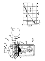
- FIG. 1 shows a processing apparatus designed as a steam sterilization apparatus 1, which has an airtight-sealable processing or sterilization chamber 2.
- a conveyor 3 is connected, which serves to evacuate the sterilization chamber 2.
- This conveyor 3 has a diaphragm pump 4, which can both promote condensate and generate vacuum.
- the conveyor 3 is at least in a partial region by means of a cooling device 5 so coolable that the conveying medium of the conveyor 3 is in liquid state or is transferred.
- the cooling device 5 has a cooling fan 6.
- the arranged in the cooling flow of the cooling fan 6 pump head 7 of the suction pump 4 has on the outside to the cooling surface magnification and the flow of the cooling flow cooling fins 8.
- the sterilization chamber 2 is evacuated to 200 millibars, for example. In this case, if necessary, by repeated evacuation of the air in the sterilization chamber 2 in exchange with the periodic inflow of steam, a particularly good air removal can also be achieved from Englumigen instruments and the like.
- a Nachvakuum is generated in the sterilization chamber 2, so that the possibly condensed on the instruments and the like water evaporate and the sterilized can be completely dry.
- the closing valve 9 is first opened and the steam flows as long as there is still overpressure in the sterilization chamber 2, via the suction pump 4. In this case, at least a portion of the vapor condenses in the suction pump 4 and is conveyed in liquid form into the open.
- the discharge valve 10 of the membrane pump which also serves as a check valve, closes in the rhythm of the pumping process.
- the suction pump 4 now draws the steam-containing conveying medium from the sterilization chamber 2, wherein the entrained steam is compressed during expulsion in the suction pump 4 to atmospheric pressure and condensed at head temperature below 100 ° C in the pump.
- the condensate is transported via the suction pump 4 to the outside. In the dead spaces, however, a residue of the condensate may remain.
- the pump head 7 of the vacuum pump by means of the cooling device 5 is so coolable that the head temperature is approximately in or preferably below the evaporation or boiling temperature corresponding to the desired in this sterilization process evaporation pressure in the sterilization chamber 2.
- the cooling device 5 for example, by a correspondingly powerful cooling fan 6 and / or by a corresponding configuration of the pump head 7 provided cooling fins 8, designed so that the pump head 7 during this Sterilization process to below 60.09 ° C is cooled.
- the sterilization chamber 2 can be evacuated quickly and efficiently.
- the cooling device 5 is designed so that the condensate located in the pump head 7 never reaches the corresponding desired in the sterilization chamber 2 evaporation pressure boiling temperature, an undesirable and power-reducing re-evaporation of the present in the pump head 7 condensate or condensate film is avoided with certainty.
- the cooling of the vacuum pump 4 in the region of the pump head 7 causes a cool running of the pump, which favors a long service life of the vacuum pump 4 and long service intervals.
- the cooling device 5 can be operated for example in the form of air cooling as an unregulated cooling system. Since only the cooling fan 6 is to be operated in such an air cooling, the energy consumption of the cooling device 5 can be kept low. In this case, the resulting in the steam sterilization apparatus 1 condensate can be reused.
- the suction pump 4 of the processing apparatus shown here is designed as a diaphragm pump.
- the diaphragm pump 4 has outlet and inlet valves 10, 11, which each have a valve disc 12 controlled by the delivery medium.
- the inlet valve 11 of the suction pump 4 is shown in more detail in FIGS. 3 and 4 in two similar embodiments.
- the diaphragm pump 4 has a housing 13, a diaphragm 14, an intermediate cover 15 and an adjoining end cover 16.
- the two covers 15, 16 together form the pump head 7.
- In the end cover 16 there is an outlet channel 17 and a connected via the suction line 19 to the processing and sterilization chamber 2 inlet channel 18.
- the valves 10, 11 are connected via leads 20 with the dome-shaped pump chamber 21 in the intermediate cover 15 in connection.
- valve disc 12 In the closed position of the valves 10, 11 is the valve disc 12 sealingly against the valve opening 22 bounding valve sealing surface 23 of the pump head. In order to limit the valve opening movement, in the open position shown in FIGS. 3 and 4, the valve disk bears against a rear support 24 serving as a stop surface.
- the circular disk-shaped valve discs 12 are held centrally by means of a pin 25 between the end cover 16 and the intermediate cover 15.
- valve disc 12 The inherent elasticity of the valve disc material usually ensures a sufficiently rapid return of the valve disc 12 in its closed position at corresponding pressure differences of the pumped medium in the pumping operation. Since with the aid of acting on the pump head cooling device 5, a re-evaporation of the pump chamber 21 or the valve chambers located condensate or condensate is avoided when using conventional suction pumps the risk that the valve discs 12 even at low liquid quantities of one or two drops on the sealing surface glued to the pump head and that the present at low absolute pressures small differential pressures are not sufficient to overcome the adhesion forces and the valve disc 12 to move.
- the sealing contact lines between the sealing side of the valve disc 12 and the at least one valve opening 22 bounding valve sealing surface 23 of the pump head 7 are substantially as formed linear contact points.
- the valve 11 shown in FIGS. 3 and 4 has for this purpose two annular projections 26 which each surround a valve opening 22 on the pump head 7. In this case, these annular projections 26 have a tapered to the contact point cross-section.
- the points of contact between the back of the valve disc 12 and the support 24 for the valve disc 12 located in the open position are here essentially designed as linear contact points.
- the rear support 24 of the valves 10, 11 is formed by the edges of a stepped projection (see Fig. 3) or more stepped projections (see Fig. 4) with preferably line-shaped contact points.
- the valve disc rear side can also serve - not shown here - point-shaped projections as back pads.
- valve disc 12 of the valves 10, 11 both the valve sealing surface 23 and the rear pad 24 touches only point or line, the forces acting as a result of a condensate film in the valve chambers on the valve disc 12 adhesion forces can be kept so low that the Valve disc 12 even at low differential pressures still smoothly oscillates between its open position and the closed position.
- inlet valve 11 is shown in Figs. 3 and 4, but also the exhaust valve 10 of the processing or steam sterilization device 1 is designed accordingly.
- the processing device shown here allows a rapid and effective pumping even moist media, the scope of this processing device is not limited to steam sterilization devices.
- FIG. 5 shows a processing device 1, which-similarly to the device according to FIG. 1 -is likewise designed as a steam sterilizer.
- the processing apparatus 1 according to FIG. 5 has a multi-stage suction pump 4 ', the pump stages 4a, 4b of which are formed by two membrane pumps following each other in the direction of flow.
- the outlet of the pumping stage 4a forming membrane pump is connected via a connecting channel 27 with the inlet of the subsequent flow direction and provided as a pumping stage 4b diaphragm pump.
- a cooling device 5 is provided, the three, each having a pumping stage 4a, 4b or the connecting channel 27 associated cooling fan 6 has.
- cooling fins 8 are provided on the outside, which are intended to increase the cooling area and serve to guide the flow of the cooling flow.
- Both the pump heads 7 of the pumping stages 4a, 4b and the connection channel 27 connecting them are cooled in such a way that both the head temperature of the pumping stages 4a, 4b measured at the pump heads 7 and the internal temperature in the connecting channel 27 are below the evaporation rate at a given evacuation pressure. or boiling temperature is cooled.
- the cooling device 5 has a cooling fan 6 associated with the pump heads 7 and the connecting channel 27. It is advantageous if at least one, preferably each of the pumping stages at its outlet and / or at its inlet a valve 10, 11 according to Figures 3, 4.
Landscapes
- Engineering & Computer Science (AREA)
- Mechanical Engineering (AREA)
- General Engineering & Computer Science (AREA)
- Health & Medical Sciences (AREA)
- Epidemiology (AREA)
- Life Sciences & Earth Sciences (AREA)
- Animal Behavior & Ethology (AREA)
- General Health & Medical Sciences (AREA)
- Public Health (AREA)
- Veterinary Medicine (AREA)
- Apparatus For Disinfection Or Sterilisation (AREA)
- Reciprocating Pumps (AREA)
- Compressor (AREA)
- Compressors, Vaccum Pumps And Other Relevant Systems (AREA)
Claims (12)
- Procédé d'évacuation d'un fluide véhiculé humide ou liquide depuis la chambre de traitement (2) d'un dispositif de traitement (1) au moyen d'un dispositif de déplacement (3) qui présente une pompe aspirante à un ou plusieurs étages (4, 4'), le fluide véhiculé pendant l'évacuation étant refroidi au cours de la trajectoire d'écoulement de façon telle que le fluide véhiculé dans le dispositif de déplacement (3) se trouve ou est converti à l'état d'agrégat liquide, caractérisé en ce que la pompe aspirante (4, 4') est conçue en tant que pompe à membrane à un ou plusieurs étages, et le refroidissement du fluide véhiculé se fait au moins dans la zone d'au moins une tête de pompe (7) de la pompe à membrane (4, 4') et/ou d'un canal de liaison (27) reliant deux étages de pompe (4a, 4b) d'une pompe à membrane à plusieurs étages (4') qui se suivent dans la direction de l'écoulement, et en ce que la tête de pompe au moins (7) et/ou le canal de liaison de la pompe à membrane (4, 4') sont refroidis en-dessous de la température d'évaporation ou d'ébullition qui existe à une pression d'évacuation donnée.
- Dispositif de traitement permettant de mettre en oeuvre le procédé selon la revendication 1, comportant une chambre de traitement (2), qui est reliée à un dispositif de déplacement (3) à des fins d'évacuation, ainsi qu'une pompe (4, 4') à un ou plusieurs étages qui est coordonnée au dispositif de déplacement (3), le dispositif de déplacement (3) pouvant être refroidi au moins dans une zone partielle au moyen d'au moins un dispositif de refroidissement (5) de façon telle que le fluide véhiculé dans le dispositif de déplacement (3) se trouve ou est converti à l'état d'agrégat liquide, caractérisé en ce que la pompe aspirante (4, 4') est conçue en tant que pompe à membrane à un ou plusieurs étages, et qu'est prévu au moins un dispositif de refroidissement destiné à refroidir au moins une tête de pompe (7) de la pompe à membrane (4, 4') et/ou un canal de liaison (27) reliant deux étages de pompe (4a, 4b) d'une pompe à membrane (4') à plusieurs étages qui suivent dans la direction de l'écoulement, et en ce que la tête de pompe (7) et/ou le canal de liaison (27) de la pompe à membrane (4, 4') peuvent être refroidis au moyen de ce dispositif de refroidissement (5) de façon telle que la température de tête de la pompe à membrane (4, 4') et/ou la température interne du canal de liaison (27) est refroidie en-dessous de la température d'évaporation ou d'ébullition qui existe à une pression d'évacuation donnée.
- Dispositif de traitement selon la revendication 2, caractérisé en ce que le dispositif de refroidissement (5) est conçu en tant que refroidissement à air, de préférence en tant que refroidissement par ventilateur.
- Dispositif de traitement selon la revendication 2 ou 3, caractérisé en ce que la tête de pompe (7) au moins disposée dans le flux de refroidissement d'un refroidissement à l'air et/ou le canal de liaison (27) de la pompe à membrane (4, 4') présente(nt) côté externe des nervures de refroidissement (8) destinées à augmenter la surface de refroidissement et éventuellement à diriger l'écoulement du flux de refroidissement.
- Dispositif selon l'une des revendications 2 à 4, caractérisé en ce qu'est intercalée dans la direction de l'écoulement prévu entre la chambre de traitement (2) et la sortie du dispositif de déplacement (3) une soupape de retenue.
- Dispositif de traitement selon l'une des revendications 2 à 5, caractérisé en ce que la soupape de retenue est de préférence la soupape de sortie (11) de la pompe à membrane (4, 4') ou la soupape de sortie d'un des étages de pompe (4a, 4b) refroidi dans la zone de la tête de pompe.
- Dispositif de traitement selon l'une des revendications 2 à 6, caractérisé en ce que le dispositif de traitement est conçu en tant que dispositif de stérilisation à la vapeur (1) et sa chambre de traitement en tant que chambre de stérilisation (2).
- Dispositif de traitement selon l'une des revendications 2 à 7, équipé d'une pompe à membrane à un ou plusieurs étages, d'au moins une soupape d'entrée se trouvant dans une tête de pompe et d'au moins une soupape de sortie, parmi lesquelles au moins une soupape présente un disque de soupape (12) commandé par le fluide véhiculé, qui, dans la position de fermeture de la soupape (10, 11), adhère de façon étanche contre une portée de siège de soupape (23) de la tête de pompe (7) entourant au moins une ouverture de soupape (22), caractérisé en ce que les points de contact étanchéifiants entre le côté d'étanchéité du disque de soupape (12) et la portée de siège de soupape (23) entourant l'ouverture de soupape (22) de la tête de pompe (7) sont essentiellement conçus en tant que points de contact en forme de ligne.
- Dispositif de traitement présentant une pompe selon la revendication 8, caractérisé en ce que les points de contact entre le côté arrière du disque de soupape (12) et un appui (24) pour le disque de soupape (12) se trouvant dans la position ouverte sont conçus essentiellement en tant que points de contact en forme de lignes et/ou de points.
- Dispositif de traitement présentant une pompe selon les revendications 8 et 9, caractérisé en ce que la portée de siège de soupape (23) et/ou le côté d'étanchéité du disque de soupape (12) présente(nt) au moins une saillie annulaire (26) entourant une ouverture de soupape (22) et possédant une section transversale de préférence conique qui se rétrécit vers les points de contact.
- Dispositif de traitement présentant une pompe selon l'une des revendications 8 à 10, caractérisé en ce que l'appui arrière (24) pour le disque de soupape (12) se trouvant en position ouverte et/ou l'arrière du disque de soupape présente(nt) en tant que points de contact en forme de ligne et/ou en forme de point un profilage de rétrécissement de la surface de contact.
- Dispositif de traitement présentant une pompe selon l'une des revendications 8 à 11, caractérisé en ce que l'appui arrière (24) pour le disque de soupape (12) est formé par les arêtes d'une saillie en forme d'escalier ou de plusieurs saillies en forme d'escalier, présentant de préférence des points de contact en forme de ligne.
Priority Applications (1)
| Application Number | Priority Date | Filing Date | Title |
|---|---|---|---|
| EP01112768A EP1126173A1 (fr) | 1997-07-30 | 1998-07-03 | Pompe, en particulier pompe aspirante à un ou plusieurs étages |
Applications Claiming Priority (3)
| Application Number | Priority Date | Filing Date | Title |
|---|---|---|---|
| DE19732808 | 1997-07-30 | ||
| DE19732808A DE19732808A1 (de) | 1997-07-30 | 1997-07-30 | Verfahren zur Evakuierung der Sterilisationskammer einer Dampfsterilisationsvorrichtung sowie Dampfsterilisationsvorrichtung |
| PCT/EP1998/004509 WO1999006699A1 (fr) | 1997-07-30 | 1998-07-03 | Procede pour l'evacuation d'un gaz humide, dispositif de traitement pour la mise en oeuvre de ce proded, ainsi que pompe d'aspiration destinee a un tel dispositif de traitement |
Related Child Applications (2)
| Application Number | Title | Priority Date | Filing Date |
|---|---|---|---|
| EP01112768A Division EP1126173A1 (fr) | 1997-07-30 | 1998-07-03 | Pompe, en particulier pompe aspirante à un ou plusieurs étages |
| EP01112768.5 Division-Into | 2001-05-26 |
Publications (3)
| Publication Number | Publication Date |
|---|---|
| EP1000244A1 EP1000244A1 (fr) | 2000-05-17 |
| EP1000244B1 EP1000244B1 (fr) | 2002-09-11 |
| EP1000244B2 true EP1000244B2 (fr) | 2007-10-31 |
Family
ID=7837368
Family Applications (2)
| Application Number | Title | Priority Date | Filing Date |
|---|---|---|---|
| EP98943745A Expired - Lifetime EP1000244B2 (fr) | 1997-07-30 | 1998-07-03 | Procede pour l'evacuation d'un gaz humide, dispositif de traitement pour la mise en oeuvre de ce prodede, ainsi que pompe d'aspiration destinee a un tel dispositif de traitement |
| EP01112768A Withdrawn EP1126173A1 (fr) | 1997-07-30 | 1998-07-03 | Pompe, en particulier pompe aspirante à un ou plusieurs étages |
Family Applications After (1)
| Application Number | Title | Priority Date | Filing Date |
|---|---|---|---|
| EP01112768A Withdrawn EP1126173A1 (fr) | 1997-07-30 | 1998-07-03 | Pompe, en particulier pompe aspirante à un ou plusieurs étages |
Country Status (6)
| Country | Link |
|---|---|
| US (1) | US6305907B1 (fr) |
| EP (2) | EP1000244B2 (fr) |
| JP (1) | JP2001512213A (fr) |
| KR (1) | KR100572708B1 (fr) |
| DE (2) | DE19732808A1 (fr) |
| WO (1) | WO1999006699A1 (fr) |
Families Citing this family (14)
| Publication number | Priority date | Publication date | Assignee | Title |
|---|---|---|---|---|
| SE517477C2 (sv) * | 2000-04-12 | 2002-06-11 | Gambro Dialysatoren | Metod för ångsterilisering av medicinska produkter |
| DE10021454C2 (de) | 2000-05-03 | 2002-03-14 | Knf Neuberger Gmbh | Vorrichtung zum Fördern feuchter Gase |
| CZ299544B6 (cs) * | 2001-12-19 | 2008-08-27 | Bmt Medical Technology S.R.O. | Malý parní sterilizátor |
| DE10233302B4 (de) * | 2002-07-22 | 2006-06-14 | Knf Neuberger Gmbh | Pumpe |
| KR20040022787A (ko) * | 2002-09-07 | 2004-03-18 | 엘지전자 주식회사 | 왕복동식 압축기의 가스 흡입장치 |
| EP1403519A1 (fr) * | 2002-09-27 | 2004-03-31 | Novo Nordisk A/S | Pompe à membrane avec membrane extensible |
| US7762796B2 (en) * | 2003-07-23 | 2010-07-27 | Hargraves Technology Corporation | Pump valve with controlled stroke |
| DE102005025322B4 (de) * | 2005-05-31 | 2011-11-17 | Hyco-Vakuumtechnik Gmbh | Heißdampfvakuumpumpe |
| JP2011516167A (ja) * | 2008-04-04 | 2011-05-26 | スリーエム イノベイティブ プロパティズ カンパニー | マイクロポンプを有する創傷ドレッシング |
| JP4512152B2 (ja) * | 2008-07-22 | 2010-07-28 | 三菱電機株式会社 | 燃料供給装置 |
| JP5493961B2 (ja) * | 2009-02-24 | 2014-05-14 | 株式会社村田製作所 | 逆止弁、流体装置およびポンプ |
| DE102009043644B4 (de) * | 2009-09-29 | 2011-07-07 | KNF Neuberger GmbH, 79112 | Mehrstufige Membran-Saugpumpe |
| CN103967751B (zh) * | 2014-05-12 | 2016-03-23 | 中国海洋石油总公司 | 一种抽真空装置 |
| JP6616611B2 (ja) * | 2015-07-23 | 2019-12-04 | エドワーズ株式会社 | 排気システム |
Family Cites Families (17)
| Publication number | Priority date | Publication date | Assignee | Title |
|---|---|---|---|---|
| DE945286C (de) * | 1953-11-01 | 1956-07-05 | Oscar Pauser | Membranverdichter |
| US3027651A (en) * | 1958-07-23 | 1962-04-03 | Leybold Hochvakuum Anlagen | Process and system for removing condensable vapors |
| DE2162031A1 (de) * | 1971-12-10 | 1973-06-14 | Auergesellschaft Gmbh | Membranpumpe |
| US4113410A (en) * | 1974-08-06 | 1978-09-12 | Otsuka Nutrition Research Institute Inc. | Liquid-sealed type vacuum pump |
| CA1047012A (fr) | 1975-02-25 | 1979-01-23 | Sumio Ando | Pompe a depression a etancheite liquide |
| US4679994A (en) * | 1981-03-09 | 1987-07-14 | Allied Corporation | Piston vacuum pump |
| US4580604A (en) * | 1983-06-23 | 1986-04-08 | Mitsubishi Denki Kabushiki Kaisha | Discharging valve device for a compressor |
| DE3533017A1 (de) * | 1985-09-16 | 1987-03-26 | Ebner Anlagen & Apparate | Verfahren zur gasfoerderung und vorrichtung hierzu |
| DE3710782A1 (de) * | 1987-03-31 | 1988-10-20 | Vacuubrand Gmbh & Co | Verfahren und vorrichtung zum abpumpen von daempfen und/oder dampfhaltigen gemischen und/oder gas-dampf-gemischen oder dgl. medien |
| DE4200838C2 (de) * | 1992-01-15 | 1994-12-22 | Knf Neuberger Gmbh | Pumpe mit vom Fördermedium gesteuerten Ventilen |
| DE4215090C2 (de) * | 1992-05-07 | 1994-11-17 | Mueller Umwelttechnik | Kanalreinigungsfahrzeug |
| US5295791A (en) * | 1993-01-19 | 1994-03-22 | Meise William H | Tapered fluid compressor & refrigeration apparatus |
| US5509790A (en) * | 1994-01-14 | 1996-04-23 | Engineering & Sales Associates, Inc. | Refrigerant compressor and motor |
| US5421368A (en) * | 1994-09-02 | 1995-06-06 | Carrier Corporation | Reed valve with tapered leg and dual radius valve stop |
| EP0788402B1 (fr) * | 1994-10-24 | 2001-05-23 | Getinge Ab | Agencement pour systemes de sterilisation en autoclave |
| DE4445054C3 (de) * | 1994-12-07 | 2002-11-21 | Melagapp Gmbh & Co Kg | Dampfsterilisator |
| JPH08261154A (ja) * | 1995-03-22 | 1996-10-08 | Toyota Autom Loom Works Ltd | ピストン型圧縮機 |
-
1997
- 1997-07-30 DE DE19732808A patent/DE19732808A1/de not_active Ceased
-
1998
- 1998-07-03 DE DE59805534T patent/DE59805534D1/de not_active Expired - Lifetime
- 1998-07-03 WO PCT/EP1998/004509 patent/WO1999006699A1/fr not_active Ceased
- 1998-07-03 JP JP2000505419A patent/JP2001512213A/ja active Pending
- 1998-07-03 EP EP98943745A patent/EP1000244B2/fr not_active Expired - Lifetime
- 1998-07-03 KR KR1019997010898A patent/KR100572708B1/ko not_active Expired - Lifetime
- 1998-07-03 EP EP01112768A patent/EP1126173A1/fr not_active Withdrawn
-
1999
- 1999-12-06 US US09/455,121 patent/US6305907B1/en not_active Expired - Lifetime
Also Published As
| Publication number | Publication date |
|---|---|
| WO1999006699A1 (fr) | 1999-02-11 |
| US6305907B1 (en) | 2001-10-23 |
| EP1000244B1 (fr) | 2002-09-11 |
| EP1126173A1 (fr) | 2001-08-22 |
| EP1000244A1 (fr) | 2000-05-17 |
| KR100572708B1 (ko) | 2006-04-24 |
| DE19732808A1 (de) | 1999-02-04 |
| KR20010012930A (ko) | 2001-02-26 |
| DE59805534D1 (de) | 2002-10-17 |
| JP2001512213A (ja) | 2001-08-21 |
Similar Documents
| Publication | Publication Date | Title |
|---|---|---|
| EP1000244B1 (fr) | Procede pour l'evacuation d'un gaz humide, dispositif de traitement pour la mise en oeuvre de ce prodede, ainsi que pompe d'aspiration destinee a un tel dispositif de traitement | |
| DE4139735C3 (de) | Entgasungsgerät | |
| EP2946112B1 (fr) | Agencement de pompes et procédé d'évacuation d'une chambre remplie de vapeur | |
| DE60311921T2 (de) | Sterilisierung mit temperaturgeregelter Diffusionsstrecke | |
| DE3884689T2 (de) | Vorrichtung zum Durchströmen von Dampf. | |
| EP1131558B1 (fr) | Procede pour acheminer des gaz humides a l'aide d'un dispositif de transport et dispositif de transport approprie pour mettre ledit procede en oeuvre | |
| WO1987007151A1 (fr) | Soupape pour recipient de sterilisation et procede de commande de la soupape | |
| DE2710968A1 (de) | Verfahren und vorrichtung zur sterilisierung von gegenstaenden in einem autoklaven | |
| DE4445054C3 (de) | Dampfsterilisator | |
| DE10112971A1 (de) | Vorrichtung zum Sterilisieren von zu befüllenden Behältern | |
| EP1278962B1 (fr) | Dispositif pour convoyer des gaz humides | |
| DE10255792A1 (de) | Verfahren zur Steuerung einer Vakuumpumpe sowie Vakuumpumpensystem | |
| DE10214331A1 (de) | Pumpeinrichtung, Verfahren zum Betreiben einer Pumpeinrichtung und dessen Verwendung bei einer Dampfturbinenanlage | |
| WO2000045861A1 (fr) | Procede et dispositif de sterilisation de recipients ou d'objets | |
| DE102012010739A1 (de) | Kondensator | |
| EP0541989A1 (fr) | Système de pompe à vide multi-étage | |
| DE3721611C2 (fr) | ||
| DE10114946A1 (de) | Verfahren zum Desinfizieren von Abfällen | |
| EP1094845B1 (fr) | Dispositif de sterilisation a la vapeur | |
| DE2503873B2 (de) | Flüssigkeitsringpumpenaggregat | |
| DE19734537C2 (de) | Verfahren und Vorrichtung zur Trocknung sterilisierter Güter in einer Sterilisierkammer | |
| DE202022106798U1 (de) | Autoklav | |
| DE102020128083B4 (de) | Vorrichtung und Verfahren zum Sterilisieren und Trocknen von medizinischen Filtern | |
| CH686115A5 (de) | Abdampf/Bruden-Verdichter fur Wormeruckgewinnung in Eindampfanlagen. | |
| DE29824550U1 (de) | Fördereinrichtung zum Fördern feuchter Gase |
Legal Events
| Date | Code | Title | Description |
|---|---|---|---|
| PUAI | Public reference made under article 153(3) epc to a published international application that has entered the european phase |
Free format text: ORIGINAL CODE: 0009012 |
|
| 17P | Request for examination filed |
Effective date: 19990601 |
|
| AK | Designated contracting states |
Kind code of ref document: A1 Designated state(s): DE FR GB |
|
| 17Q | First examination report despatched |
Effective date: 20010502 |
|
| GRAG | Despatch of communication of intention to grant |
Free format text: ORIGINAL CODE: EPIDOS AGRA |
|
| GRAG | Despatch of communication of intention to grant |
Free format text: ORIGINAL CODE: EPIDOS AGRA |
|
| GRAH | Despatch of communication of intention to grant a patent |
Free format text: ORIGINAL CODE: EPIDOS IGRA |
|
| GRAG | Despatch of communication of intention to grant |
Free format text: ORIGINAL CODE: EPIDOS AGRA |
|
| GRAH | Despatch of communication of intention to grant a patent |
Free format text: ORIGINAL CODE: EPIDOS IGRA |
|
| GRAH | Despatch of communication of intention to grant a patent |
Free format text: ORIGINAL CODE: EPIDOS IGRA |
|
| GRAA | (expected) grant |
Free format text: ORIGINAL CODE: 0009210 |
|
| AK | Designated contracting states |
Kind code of ref document: B1 Designated state(s): DE FR GB |
|
| REG | Reference to a national code |
Ref country code: GB Ref legal event code: FG4D Free format text: NOT ENGLISH |
|
| REF | Corresponds to: |
Ref document number: 59805534 Country of ref document: DE Date of ref document: 20021017 |
|
| GBT | Gb: translation of ep patent filed (gb section 77(6)(a)/1977) |
Effective date: 20030110 |
|
| ET | Fr: translation filed | ||
| PLBQ | Unpublished change to opponent data |
Free format text: ORIGINAL CODE: EPIDOS OPPO |
|
| PLBI | Opposition filed |
Free format text: ORIGINAL CODE: 0009260 |
|
| PLAX | Notice of opposition and request to file observation + time limit sent |
Free format text: ORIGINAL CODE: EPIDOSNOBS2 |
|
| 26 | Opposition filed |
Opponent name: ASF THOMAS INDUSTRIES GMBH Effective date: 20030611 |
|
| PLAX | Notice of opposition and request to file observation + time limit sent |
Free format text: ORIGINAL CODE: EPIDOSNOBS2 |
|
| PLBB | Reply of patent proprietor to notice(s) of opposition received |
Free format text: ORIGINAL CODE: EPIDOSNOBS3 |
|
| RDAF | Communication despatched that patent is revoked |
Free format text: ORIGINAL CODE: EPIDOSNREV1 |
|
| APBP | Date of receipt of notice of appeal recorded |
Free format text: ORIGINAL CODE: EPIDOSNNOA2O |
|
| APBM | Appeal reference recorded |
Free format text: ORIGINAL CODE: EPIDOSNREFNO |
|
| APBQ | Date of receipt of statement of grounds of appeal recorded |
Free format text: ORIGINAL CODE: EPIDOSNNOA3O |
|
| APAH | Appeal reference modified |
Free format text: ORIGINAL CODE: EPIDOSCREFNO |
|
| PLAB | Opposition data, opponent's data or that of the opponent's representative modified |
Free format text: ORIGINAL CODE: 0009299OPPO |
|
| R26 | Opposition filed (corrected) |
Opponent name: ASF THOMAS INDUSTRIES GMBH Effective date: 20030611 |
|
| APBU | Appeal procedure closed |
Free format text: ORIGINAL CODE: EPIDOSNNOA9O |
|
| PUAH | Patent maintained in amended form |
Free format text: ORIGINAL CODE: 0009272 |
|
| STAA | Information on the status of an ep patent application or granted ep patent |
Free format text: STATUS: PATENT MAINTAINED AS AMENDED |
|
| 27A | Patent maintained in amended form |
Effective date: 20071031 |
|
| AK | Designated contracting states |
Kind code of ref document: B2 Designated state(s): DE FR GB |
|
| GBTA | Gb: translation of amended ep patent filed (gb section 77(6)(b)/1977) | ||
| ET3 | Fr: translation filed ** decision concerning opposition | ||
| REG | Reference to a national code |
Ref country code: FR Ref legal event code: PLFP Year of fee payment: 19 |
|
| REG | Reference to a national code |
Ref country code: FR Ref legal event code: PLFP Year of fee payment: 20 |
|
| PGFP | Annual fee paid to national office [announced via postgrant information from national office to epo] |
Ref country code: DE Payment date: 20170817 Year of fee payment: 20 Ref country code: FR Payment date: 20170720 Year of fee payment: 20 Ref country code: GB Payment date: 20170724 Year of fee payment: 20 |
|
| REG | Reference to a national code |
Ref country code: DE Ref legal event code: R071 Ref document number: 59805534 Country of ref document: DE |
|
| REG | Reference to a national code |
Ref country code: GB Ref legal event code: PE20 Expiry date: 20180702 |
|
| PG25 | Lapsed in a contracting state [announced via postgrant information from national office to epo] |
Ref country code: GB Free format text: LAPSE BECAUSE OF EXPIRATION OF PROTECTION Effective date: 20180702 |