EP1000310B1 - Zündeinrichtung für eine insassenschutzvorrichtung eines kraftfahrzeuges - Google Patents
Zündeinrichtung für eine insassenschutzvorrichtung eines kraftfahrzeuges Download PDFInfo
- Publication number
- EP1000310B1 EP1000310B1 EP98943693A EP98943693A EP1000310B1 EP 1000310 B1 EP1000310 B1 EP 1000310B1 EP 98943693 A EP98943693 A EP 98943693A EP 98943693 A EP98943693 A EP 98943693A EP 1000310 B1 EP1000310 B1 EP 1000310B1
- Authority
- EP
- European Patent Office
- Prior art keywords
- contact pins
- ignition device
- ignition
- gauge ring
- heads
- Prior art date
- Legal status (The legal status is an assumption and is not a legal conclusion. Google has not performed a legal analysis and makes no representation as to the accuracy of the status listed.)
- Expired - Lifetime
Links
- 230000009969 flowable effect Effects 0.000 claims abstract description 4
- 239000011521 glass Substances 0.000 claims description 7
- 239000000463 material Substances 0.000 claims description 7
- 239000002184 metal Substances 0.000 claims description 4
- 239000012777 electrically insulating material Substances 0.000 claims 3
- 238000004873 anchoring Methods 0.000 claims 1
- 210000003128 head Anatomy 0.000 description 11
- 238000004519 manufacturing process Methods 0.000 description 8
- 238000012544 monitoring process Methods 0.000 description 7
- 239000004033 plastic Substances 0.000 description 4
- 238000010276 construction Methods 0.000 description 3
- 239000012212 insulator Substances 0.000 description 3
- 241000587161 Gomphocarpus Species 0.000 description 2
- 239000007788 liquid Substances 0.000 description 2
- 239000000203 mixture Substances 0.000 description 2
- 210000003739 neck Anatomy 0.000 description 2
- 238000007789 sealing Methods 0.000 description 2
- 241001417935 Platycephalidae Species 0.000 description 1
- 230000004323 axial length Effects 0.000 description 1
- 239000011230 binding agent Substances 0.000 description 1
- 239000002360 explosive Substances 0.000 description 1
- 238000009472 formulation Methods 0.000 description 1
- 239000000446 fuel Substances 0.000 description 1
- 238000010438 heat treatment Methods 0.000 description 1
- 238000009434 installation Methods 0.000 description 1
- 239000011810 insulating material Substances 0.000 description 1
- 230000008018 melting Effects 0.000 description 1
- 238000002844 melting Methods 0.000 description 1
- 229910001092 metal group alloy Inorganic materials 0.000 description 1
- 230000037452 priming Effects 0.000 description 1
- 238000010079 rubber tapping Methods 0.000 description 1
- 239000000565 sealant Substances 0.000 description 1
- 239000007787 solid Substances 0.000 description 1
- 239000000126 substance Substances 0.000 description 1
- 210000004127 vitreous body Anatomy 0.000 description 1
- 238000003466 welding Methods 0.000 description 1
Images
Classifications
-
- B—PERFORMING OPERATIONS; TRANSPORTING
- B60—VEHICLES IN GENERAL
- B60R—VEHICLES, VEHICLE FITTINGS, OR VEHICLE PARTS, NOT OTHERWISE PROVIDED FOR
- B60R21/00—Arrangements or fittings on vehicles for protecting or preventing injuries to occupants or pedestrians in case of accidents or other traffic risks
- B60R21/02—Occupant safety arrangements or fittings, e.g. crash pads
- B60R21/16—Inflatable occupant restraints or confinements designed to inflate upon impact or impending impact, e.g. air bags
-
- F—MECHANICAL ENGINEERING; LIGHTING; HEATING; WEAPONS; BLASTING
- F42—AMMUNITION; BLASTING
- F42B—EXPLOSIVE CHARGES, e.g. FOR BLASTING, FIREWORKS, AMMUNITION
- F42B3/00—Blasting cartridges, i.e. case and explosive
- F42B3/10—Initiators therefor
- F42B3/12—Bridge initiators
- F42B3/124—Bridge initiators characterised by the configuration or material of the bridge
-
- F—MECHANICAL ENGINEERING; LIGHTING; HEATING; WEAPONS; BLASTING
- F42—AMMUNITION; BLASTING
- F42B—EXPLOSIVE CHARGES, e.g. FOR BLASTING, FIREWORKS, AMMUNITION
- F42B3/00—Blasting cartridges, i.e. case and explosive
- F42B3/10—Initiators therefor
- F42B3/103—Mounting initiator heads in initiators; Sealing-plugs
-
- F—MECHANICAL ENGINEERING; LIGHTING; HEATING; WEAPONS; BLASTING
- F42—AMMUNITION; BLASTING
- F42B—EXPLOSIVE CHARGES, e.g. FOR BLASTING, FIREWORKS, AMMUNITION
- F42B3/00—Blasting cartridges, i.e. case and explosive
- F42B3/10—Initiators therefor
- F42B3/12—Bridge initiators
- F42B3/125—Bridge initiators characterised by the configuration of the bridge initiator case
- F42B3/127—Bridge initiators characterised by the configuration of the bridge initiator case the case having burst direction defining elements
-
- F—MECHANICAL ENGINEERING; LIGHTING; HEATING; WEAPONS; BLASTING
- F42—AMMUNITION; BLASTING
- F42B—EXPLOSIVE CHARGES, e.g. FOR BLASTING, FIREWORKS, AMMUNITION
- F42B3/00—Blasting cartridges, i.e. case and explosive
- F42B3/10—Initiators therefor
- F42B3/18—Safety initiators resistant to premature firing by static electricity or stray currents
-
- B—PERFORMING OPERATIONS; TRANSPORTING
- B60—VEHICLES IN GENERAL
- B60R—VEHICLES, VEHICLE FITTINGS, OR VEHICLE PARTS, NOT OTHERWISE PROVIDED FOR
- B60R21/00—Arrangements or fittings on vehicles for protecting or preventing injuries to occupants or pedestrians in case of accidents or other traffic risks
- B60R21/02—Occupant safety arrangements or fittings, e.g. crash pads
- B60R21/16—Inflatable occupant restraints or confinements designed to inflate upon impact or impending impact, e.g. air bags
- B60R21/26—Inflatable occupant restraints or confinements designed to inflate upon impact or impending impact, e.g. air bags characterised by the inflation fluid source or means to control inflation fluid flow
- B60R2021/26029—Ignitors
Definitions
- the invention relates to an ignition device for a Occupant protection device of a motor vehicle, in particular for an inflatable impact protection cushion (airbag).
- airbag inflatable impact protection cushion
- Ignition devices for occupant protection devices Motor vehicle e.g. Belt tensioner or airbag systems are known from DE 4102275 C1.
- Such ignition devices have in an ignition chamber as an ignition element low-resistance wire and an igniter on the with sufficient heating or when melting the Resistance wire is ignited.
- German patent application DE 4429175 A1 discloses one Ignition device with a housing made of a metal alloy and with a fitting ring inserted in the housing, in which a glass insulator is located. Are in this isolator Contact pins melted into the ignition chamber protruding ends with the front of the insulator complete and with a welded resistance wire are connected, which acts as an ignition element.
- This construction also has the disadvantage that the Flammable substance during vibrations, blows or Temperature changes due to the forces and Shear loads can detach from the vitreous body, so that the contact with the resistance wire deteriorates or even will be annulled. In such a case, the detonator can no longer be ignited safely.
- Such an ignition device is not in practice can be used reliably because of the sealing problems in particular between the plastic material and the nail heads considerably are. Furthermore, there is also the problem that with shaking movements acting on the ignition device, Impacts or temperature changes of the resistance wire and the Can come out of contact with each other so that a reliable ignition is no longer guaranteed.
- the target spark gap is the shortest Distance between two different conductive parts inside the igniter.
- the object of the present invention is therefore a Ignition device for an occupant protection device To create motor vehicle, its manufacture simple and is less complex and in particular the step of Contact grinding is not required.
- the invention is also based on the object Ignition device to create that easily and without additional Effort to the manufacturers of surveillance electronics predetermined values of the trigger signals can be adjusted.
- Another object of the present invention is to: Ignition device with an integrated surge arrester to be provided of no additional elements as well Manufacturing steps required.
- the manufacturing effort is reduced the igniter through the use of nail-shaped trained and protruding into the ignition chamber Contact pins with a resistance wire on their heads attached desired length, preferably welded.
- the housing starts with liquid detonator filled the heads of the contact pins and envelops the resistance wire and then solidifies.
- igniters are known:
- the German patent DE 4319919 C1 describes explosives which are used in the Manufacturing are flowable and later solidify.
- Liquid fuels are preferred as the primer pyrotechnic mixtures with a binder are used then freeze.
- a relatively large area or linear spark gap as surge arrester intended.
- the Spark gap according to the invention is preferred thereby achieved that the contact pins of an electrically conductive Extension of the housing to be surrounded, which extends over a extends considerable length of the necks of the contact pins. This Length is z. B. roughly comparable to the scope of Contact pins selected.
- the present invention as explained above, the Tapping off the contact pins and their surface grinding with the Insulator glass avoided.
- the result is a substantial one Reduction in manufacturing costs and Manufacturing costs and easy universal adaptability to the specifications of the respective manufacturer of the release and Monitoring electronics.
- a further reduction in the Manufacturing effort is carried out by the invention geometry-related integrated surge arrester.
- the construction according to the invention meets the requirements of Functional guarantee for at least ten years and is gas-tight and especially helium-tight.
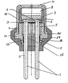
- contact pins are of a nail-shaped design 1, which have a neck 2 and a head 3, in one Fitting ring 4 melted into an insulating glass material 5 and are stuck at a defined distance from each other.
- the heads 3 of the contact pins 1 protrude from the fitting ring 4.
- On Resistance wire 6 is on the heads 3 of the contact pins 1st welded.
- a set sleeve 7 is placed on the fitting ring 2 placed. This sleeve 7 is connected to the fitting ring 4.
- the resulting volume forms an ignition chamber 8.
- a sealant 21 is placed on the bottom of the ignition chamber 8 applied; then the ignition chamber becomes flowable Primer 9 filled up, which then solidifies. After that a metal cap 10 is placed on its face has a burst surface 11 and with its edge on the opposite side with a radial flange 22 of the Fit ring 4 is connected by resistance welding at RW.
- the Fitting ring 4 On the heads 3 of the contact pins 1 facing away from the Fitting ring 4 has a cylindrical extension 23, of the contact pins 1 over a relatively long distance envelops. Between the inner wall of the extension 23 and the Contact pins 1, a spark gap F is formed. The radial distance between the extension 23 and the respective Contact pin 1 is smaller than the distance between the heads 3 of the contact pins 1 and the metal cap 10. This will in the event of overvoltages, any sparks from the housing 4, 10 to the Do not skip contact pins 1 and heads 3. at The sparks can span the entire circumference skip the contact pins.
- the axial length of the Extension 23 is selected so that at high overvoltages can jump several sparks at the same time.
- the radial width of the spark gap F is preferably 0.3 mm, but can be any suitable value between 0.1 and 0.9 mm assume.
- the inner edge of the extension facing the contact pins can still be roughened, e.g. B. in the manner of a thread 24 be trained to facilitate the spark jump.
- the extension 23 becomes electric with a plug 25 insulating material sealed, the spark gap F remains free.
- the plug 25, the contact pins 1 and the Ignition chamber 8 edge of the cap 10 are of a Plastic sheath 26 envelops, which increases the stability of the Facility is increased and additional protection is guaranteed.
- the effective resistance of the resistance wire 6 is surprisingly only a function of the distance between the welds on the ends of the wire. This fact enables the contact pins to remain at the same distance from each other by varying the distance between the welds one another the trigger signal of the monitoring electronics to provide an adjusted resistance value.
Landscapes
- Engineering & Computer Science (AREA)
- General Engineering & Computer Science (AREA)
- Mechanical Engineering (AREA)
- Air Bags (AREA)
- Automotive Seat Belt Assembly (AREA)
Abstract
Description
Claims (10)
- Zündeinrichtung für eine Insassenschutzvorrichtung eines Kraftfahrzeuges und insbesondere für ein aufblasbares Aufprallschutzkissen (Airbag) mit zwei in einem Passring (4), der mit elektrisch isolierendem Material (5) ausgefüllt ist, eingesetzten nagelförmigen Kontaktstiften (1) mit je einem Hals (2) und einem Kopf (3), wobei auf dem Passring ein kappenförmiges Gehäuse (7, 10) aufgesetzt ist, wodurch zwischen Passring (4) und Gehäuse (7, 10) eine Zündkammer (8) gebildet wird, und wobei zwischen den in der Zündkammer (8) gelegenen Oberseiten der Köpfe (3) der Kontaktstifte (1) ein elektrisch mit diesem verbundener Widerstandsdraht (6) vorgesehen und die Zündkammer (8) mit Zündstoff (9) gefüllt ist, dadurch gekennzeichnet, daß die nagelartigen Kontaktstifte (1) in ein von dem Passring (4) umgebenes Glasmaterial (5) eingeschmolzen sind, daß die Kontaktstifte (1) mit ihren Köpfen (3) vollständig in die Zündkammer (8) hineinragen und gemeinsam mit dem Widerstandsdraht (6) von dem bei der Herstellung der Zündeinrichtung fließfähigen und anschließend erstarrenden Zündstoff (9) vollständig umhüllt sind, wodurch der Zündstoff (9) an den Köpfen (3) der Kontaktstifte (1) verankert ist.
- Zündeinrichtung nach Anspruch 1, dadurch gekennzeichnet, dass der Widerstandsdraht (6) auf der Oberseite der Köpfe (3) der Kontaktstifte (1) angeschweisst ist.
- Zündeinrichtung nach einem der vorhergehenden Ansprüche, dadurch gekennzeichnet, dass die Kontaktstifte (1) gerade ausgebildet sind.
- Zündeinrichtung nach einem der vorhergehenden Ansprüche, dadurch gekennzeichnet, daß das Gehäuse (4, 7, 10) eine Buchse (7) und eine diese umgebende und mit dem Passring (4) verbundene Kappe (10) aufweist, wobei diese Kappe (10) eine Berstfläche (11) aufweist und die Zündkammer (8) im Wesentlichen durch die Hülse und die Berstfläche begrenzt ist.
- Zündeinrichtung nach einem der vorhergehenden Ansprüche, dadurch gekennzeichnet, dass das Gehäuse (4, 7, 10) mit dem Passring (4) aus Metall besteht.
- Zündeinrichtung nach einem der vorhergehenden Ansprüche, dadurch gekennzeichnet, daß die Zündeinrichtung auf der der Zündkammer gegenüberliegenden Seite der Kontaktstifte mit einem Pfropfen aus elektrisch isolierendem Material unter Freilassung der Anschlußenden der Kontaktstifte (1) umgeben ist.
- Zündeinrichtung für eine Insassenschutzvorrichtung eines Kraftfahrzeuges und insbesondere für ein aufblasbares Aufprallschutzkissen (Airbag), nach Anspruch 1, mit zwei in einem Passring (4), der mit elektrisch isolierendem Material (5) ausgefüllt ist, eingesetzten Kontaktstiften (1), wobei auf dem Passring ein kappenförmiges Gehäuse (7, 10) aufgesetzt ist, sodass zwischen Passring (4) und Gehäuse (7, 10) eine Zündkammer (8) gebildet wird, die mit Zündstoff (9) gefüllt ist, und.wobei zwischen den in der Zündkammer (8) gelegenen Oberseiten der Kontaktstifte (1) ein elektrisch mit diesen verbundener Widerstandsdraht (6) vorgesehen ist, dadurch gekennzeichnet, daß der Passring (4) aus Metall ist und einen Fortsatz aufweist, der die Kontaktstifte (1) so umgibt, daß zwischen der Innenwand des Fortsatzes (22) und den Kontaktstiften (1) eine Funkenstrecke (F) ausgebildet ist, wobei die Funkenstrecke (F) eine Dimension hat, die kleiner als der ansonsten kleinste Abstand zwischen dem elektrisch leitenden Gehäuse und den Kontaktstiften ist, und dass die Innenwand des Fortsatzes (23) aufgerauht, vorzugsweise mit einem Gewinde versehen ist.
- Zündeinrichtung nach Anspruch 7, dadurch gekennzeichnet, daß die Innenwand des Fortsatzes (23) mit einem Gewinde versehen ist.
- Zündeinrichtung nach Anspruch 7 oder 8, dadurch gekennzeichnet, daß die Funkenstrecke eine radiale Breite zwischen 0,1 mm und 0,9 mm, vorzugsweise etwa 0,3 mm aufweist.
- Zündeinrichtung nach einem der Ansprüche 7 bis 9, Anspruch 7 oder 8, dadurch gekennzeichnet, dass der Fortsatz (23) mit einem elektrisch isolierendem Pfropfen (24) verschlossen ist, der die Funkensstrecke (F) frei lässt.
Priority Applications (1)
| Application Number | Priority Date | Filing Date | Title |
|---|---|---|---|
| EP01121108A EP1164349B1 (de) | 1997-08-01 | 1998-07-14 | Zündeinrichtung für eine Insassenschutzvorrichtung eines Kraftfahrzeugs |
Applications Claiming Priority (3)
| Application Number | Priority Date | Filing Date | Title |
|---|---|---|---|
| DE19733353 | 1997-08-01 | ||
| DE19733353A DE19733353C1 (de) | 1997-08-01 | 1997-08-01 | Zündeinrichtung für eine Insassenschutzvorrichtung eines Kraftfahrzeuges |
| PCT/DE1998/001968 WO1999006786A1 (de) | 1997-08-01 | 1998-07-14 | Zündeinrichtung für eine insassenschutzvorrichtung eines kraftfahrzeuges |
Related Child Applications (1)
| Application Number | Title | Priority Date | Filing Date |
|---|---|---|---|
| EP01121108A Division EP1164349B1 (de) | 1997-08-01 | 1998-07-14 | Zündeinrichtung für eine Insassenschutzvorrichtung eines Kraftfahrzeugs |
Publications (2)
| Publication Number | Publication Date |
|---|---|
| EP1000310A1 EP1000310A1 (de) | 2000-05-17 |
| EP1000310B1 true EP1000310B1 (de) | 2002-03-27 |
Family
ID=7837730
Family Applications (2)
| Application Number | Title | Priority Date | Filing Date |
|---|---|---|---|
| EP98943693A Expired - Lifetime EP1000310B1 (de) | 1997-08-01 | 1998-07-14 | Zündeinrichtung für eine insassenschutzvorrichtung eines kraftfahrzeuges |
| EP01121108A Expired - Lifetime EP1164349B1 (de) | 1997-08-01 | 1998-07-14 | Zündeinrichtung für eine Insassenschutzvorrichtung eines Kraftfahrzeugs |
Family Applications After (1)
| Application Number | Title | Priority Date | Filing Date |
|---|---|---|---|
| EP01121108A Expired - Lifetime EP1164349B1 (de) | 1997-08-01 | 1998-07-14 | Zündeinrichtung für eine Insassenschutzvorrichtung eines Kraftfahrzeugs |
Country Status (18)
| Country | Link |
|---|---|
| US (1) | US6446557B1 (de) |
| EP (2) | EP1000310B1 (de) |
| JP (1) | JP2001512227A (de) |
| KR (1) | KR20010022540A (de) |
| CN (1) | CN1080870C (de) |
| AR (1) | AR016573A1 (de) |
| AT (2) | ATE237120T1 (de) |
| BR (1) | BR9811811A (de) |
| CA (1) | CA2298710A1 (de) |
| DE (3) | DE19733353C1 (de) |
| ES (1) | ES2178253T3 (de) |
| ID (1) | ID20641A (de) |
| IL (1) | IL134136A0 (de) |
| MY (1) | MY132951A (de) |
| PT (1) | PT1000310E (de) |
| TR (1) | TR200000267T2 (de) |
| WO (1) | WO1999006786A1 (de) |
| ZA (1) | ZA986660B (de) |
Cited By (2)
| Publication number | Priority date | Publication date | Assignee | Title |
|---|---|---|---|---|
| DE202012002149U1 (de) | 2012-03-05 | 2012-07-10 | Nst Newco Technologies Gmbh | Vorrichtung zum Irritieren von Personen oder Personenansammlungen |
| EP2642255B1 (de) * | 2012-03-22 | 2023-06-14 | Krohne Messtechnik GmbH | Messgerät |
Families Citing this family (42)
| Publication number | Priority date | Publication date | Assignee | Title |
|---|---|---|---|---|
| DE19948607C1 (de) * | 1999-10-08 | 2001-01-11 | Guenter Duerschinger | Zündeinrichtung für ein Insassen-Rückhaltesystem |
| AU2503301A (en) * | 1999-11-24 | 2001-06-04 | Gunter Durschinger | Firing capsule with a safety device for an occupant restraining system |
| ES2202218T3 (es) | 1999-12-17 | 2004-04-01 | Schott Glas | Capsula fulminante activable inductivamente para sistemas de retencion de pasajeros y circuito de prueba para esta capsula fulminante. |
| DE19961134C1 (de) * | 1999-12-17 | 2001-02-01 | Guenter Duerschinger | Induktiv aktivierbare Zündkapsel für Insassen-Rückhaltesysteme und Prüfschaltung für diese Zündkapsel |
| DE10048869B4 (de) * | 2000-10-02 | 2005-09-22 | Schott Ag | Induktiv aktivierbare Zündkapsel |
| DE10028374C1 (de) | 2000-06-08 | 2001-10-25 | Guenter Duerschinger | Strombrücke für Zündkapseln |
| DE10036455C2 (de) * | 2000-07-26 | 2002-06-20 | Willi Luebbers | Zündeinrichtung mit einer Sollburchstelle für einen Treibsatz des Gasgenerators einer Insassenschutzvorrichtung in Kraftfahrzeugen |
| JP4813642B2 (ja) * | 2000-08-09 | 2011-11-09 | ダイセル化学工業株式会社 | 電気式イニシエータ及びそれを用いたイニシエータ組立体 |
| US20020069781A1 (en) * | 2000-12-07 | 2002-06-13 | Vahan Avetisian | Recessed glass header for pyrotechnic initiators |
| US6848365B2 (en) * | 2000-12-08 | 2005-02-01 | Special Devices, Inc. | Initiator with an internal sleeve retaining a pyrotechnic charge and methods of making same |
| DE10111715A1 (de) | 2001-03-12 | 2002-10-02 | Nico Pyrotechnik | Anzündvorrichtung für die Treibladung einer Insassenschutzvorrichtung |
| EP1286125A4 (de) * | 2001-04-27 | 2004-10-20 | Daicel Chem | Anzünder und einem mit diesem anzünder versehenem gasgenerator |
| DE10125354C2 (de) * | 2001-05-23 | 2003-11-27 | Nico Pyrotechnik | Zündvorrichtung für eine Insassenschutzeinrichtung eines Kraftfahrzeuges |
| US6915744B2 (en) * | 2001-07-05 | 2005-07-12 | Special Devices, Inc. | Pyrotechnic initiator with on-board control circuitry |
| DE10133221A1 (de) * | 2001-07-09 | 2002-10-17 | Trw Airbag Sys Gmbh & Co Kg | Anzünder |
| DE10133223A1 (de) * | 2001-07-09 | 2002-10-17 | Trw Airbag Sys Gmbh & Co Kg | Anzünder |
| JP3864823B2 (ja) * | 2002-03-28 | 2007-01-10 | トヨタ自動車株式会社 | イニシエータ、インフレータおよび車両の乗員頭部保護エアバッグ装置 |
| JP3906910B2 (ja) | 2002-03-29 | 2007-04-18 | トヨタ自動車株式会社 | イニシエータ |
| US20030192446A1 (en) * | 2002-04-16 | 2003-10-16 | Paul Berg | Header with overlying eyelet |
| US20040000248A1 (en) * | 2002-07-01 | 2004-01-01 | Vahan Avetisian | Initiator with a bridgewire in contact with slurry-loaded pyrotechnic charge at a position of relatively low void formation |
| US6877431B2 (en) * | 2002-10-21 | 2005-04-12 | Schott Glas | Hermetically sealed electrical feed-through device with a bent isolated pin in a circular glass seal |
| US6874423B2 (en) * | 2002-10-21 | 2005-04-05 | Schott Glas | Hermetically sealed electrical feed-through device with a straight isolated pin in an offset oval glass seal |
| US6874422B2 (en) * | 2002-10-21 | 2005-04-05 | Schott Glas | Hermetically sealed electrical feed-through device with an oval-cross-sectioned isolated pin in a circular glass seal |
| US6907827B2 (en) * | 2002-11-14 | 2005-06-21 | Special Devices, Inc. | Pyrotechnic initiator having output can with encapsulation material retention feature |
| US20040244624A1 (en) * | 2003-01-31 | 2004-12-09 | Hiroshi Harada | Parts of igniter |
| DE10311626B4 (de) * | 2003-03-17 | 2006-08-10 | Trw Airbag Systems Gmbh | Anzünder und Verfahren zu dessen Herstellung |
| DE10320731B4 (de) | 2003-05-08 | 2005-07-21 | Nico-Pyrotechnik Hanns-Jürgen Diederichs GmbH & Co. KG | Schnellfeuerwaffe |
| DE10348382A1 (de) * | 2003-10-17 | 2005-05-25 | Daimlerchrysler Ag | Gasgenerator mit Ladungsableitstrecke |
| US20060208474A1 (en) * | 2003-12-24 | 2006-09-21 | Nippon Kayaku Kabushiki Kaisha | Gas producer |
| JP4335725B2 (ja) * | 2004-03-30 | 2009-09-30 | 日本化薬株式会社 | ガス発生器 |
| US20070163457A1 (en) * | 2004-04-16 | 2007-07-19 | Nippon Kayaku Kabushiki Kaisha | Igniter and gas generator having the same |
| FR2875594B1 (fr) * | 2004-09-21 | 2007-03-16 | Ncs Pyrotechnie & Tech | Initiateur electro-pyrotechnique |
| US20100181748A1 (en) * | 2007-06-13 | 2010-07-22 | Nipponkayaku Kabushikikaisha | Squib, Gas Generation for Inflating Air Bag and Gas Generator for Seat Belt Pretensioner |
| DE102008053539A1 (de) * | 2008-10-28 | 2010-04-29 | Trw Airbag Systems Gmbh | Pyrotechnischer Anzünder und Verfahren zur Herstellung eines solchen pyrotechnischen Anzünders |
| DE102010051661A1 (de) | 2009-11-17 | 2011-07-14 | NST Newco Safety Technologies GmbH, 24159 | Pyrotechnisches System zum Schützen von Personen, Fahrzeugen und/oder Objekten |
| US10857967B2 (en) * | 2019-02-27 | 2020-12-08 | Autoliv Asp, Inc. | Initiator for an automotive safety device |
| DE102012010608B4 (de) * | 2012-05-16 | 2025-02-13 | Zf Airbag Germany Gmbh | Anzünder und Verfahren zur Herstellung eines Anzünders für einen Gasgenerator |
| DE102013017383A1 (de) * | 2013-10-21 | 2015-04-23 | Trw Airbag Systems Gmbh | Anzündeinheit, insbesondere für einen Gasgenerator, Gasgenerator, Gassackmodul, Fahrzeugsicherheitssystem und Verfahren zur Herstellung einer Anzündeinheit |
| DE102014007809B4 (de) * | 2014-05-26 | 2017-02-16 | Elisabeth Dürschinger | Induktiv aktivierbare Zündkapsel für Insassen-Rückhaltesysteme |
| JP6706190B2 (ja) | 2016-11-29 | 2020-06-03 | 株式会社ダイセル | ガス発生器 |
| US11406523B2 (en) * | 2017-07-12 | 2022-08-09 | Theo Roubos | Orthosis |
| DE102018109719A1 (de) * | 2018-04-23 | 2019-10-24 | Joyson Safety Systems Germany Gmbh | Anzünder für einen Gasgenerator eines Gassackmoduls und Verfahren zum Herstellen eines Anzünders |
Family Cites Families (24)
| Publication number | Priority date | Publication date | Assignee | Title |
|---|---|---|---|---|
| FR2087044A5 (de) | 1970-04-29 | 1971-12-31 | Explosifs Produit Chimiq | |
| US4306499A (en) * | 1978-04-03 | 1981-12-22 | Thiokol Corporation | Electric safety squib |
| US4307663A (en) | 1979-11-20 | 1981-12-29 | Ici Americas Inc. | Static discharge disc |
| DE3118137C2 (de) * | 1981-05-07 | 1986-04-24 | Siemens AG, 1000 Berlin und 8000 München | Gasentladungs-Überspannungsableiter mit parallel geschalteter Luftfunkenstrecke |
| DE4102275C1 (en) * | 1991-01-26 | 1992-06-17 | Bayern-Chemie Gesellschaft Fuer Flugchemische Antriebe Mbh, 8261 Aschau, De | Gas generator for e.g. airbag in cars - includes beaker shaped central pipe which is designed so that it cannot become detached |
| US5452661A (en) * | 1992-06-15 | 1995-09-26 | Neff; George R. | Hermetically sealed devices for leak detection |
| JP2700100B2 (ja) * | 1993-05-28 | 1998-01-19 | 日本工機株式会社 | イグナイター |
| DE4319919C1 (de) * | 1993-06-16 | 1995-01-19 | Diehl Gmbh & Co | Gießvorrichtung für kugelförmige Sprengstoffstücke |
| US5596163A (en) * | 1993-08-25 | 1997-01-21 | Ems-Patvag Ag | Gas generator igniting capsule |
| CH688564A5 (de) * | 1993-08-25 | 1997-11-14 | Ems Patvag Ag | Gekapselter elektrischer Zuender mit integriertem Ueberspannungsableiter fuer einen Gasgenerator. |
| US5648634A (en) * | 1993-10-20 | 1997-07-15 | Quantic Industries, Inc. | Electrical initiator |
| US5728964A (en) * | 1993-10-20 | 1998-03-17 | Quantic Industries, Inc. | Electrical initiator |
| ZA948566B (en) | 1993-11-18 | 1995-05-18 | Ici America Inc | Airbag igniter and method of manufacture |
| US5503077A (en) * | 1994-03-29 | 1996-04-02 | Halliburton Company | Explosive detonation apparatus |
| US5621183A (en) * | 1995-01-12 | 1997-04-15 | Trw Inc. | Initiator for an air bag inflator |
| US5556132A (en) * | 1995-04-13 | 1996-09-17 | Trw Inc. | Vehicle occupant restraint with auto ignition material |
| US5616881A (en) * | 1995-05-30 | 1997-04-01 | Morton International, Inc. | Inflator socket pin collar for integrated circuit initaitor with integral metal oxide varistor for electro-static discharge protections |
| US5558366A (en) * | 1995-08-22 | 1996-09-24 | Trw Inc. | Initiator assembly for air bag inflator |
| US5613706A (en) * | 1995-12-13 | 1997-03-25 | Morton International, Inc. | Self-contained inflator pyrotechnic initiator |
| US5672841A (en) * | 1995-12-15 | 1997-09-30 | Morton International, Inc. | Inflator initiator with zener diode electrostatic discharge protection |
| US5932832A (en) * | 1996-04-15 | 1999-08-03 | Autoliv Asp, Inc. | High pressure resistant initiator with integral metal oxide varistor for electro-static discharge protection |
| US5695215A (en) * | 1996-04-24 | 1997-12-09 | Trw Inc. | Fill tube for air bag inflator |
| US5732634A (en) * | 1996-09-03 | 1998-03-31 | Teledyne Industries, Inc. | Thin film bridge initiators and method of manufacture |
| US5988069A (en) * | 1996-11-12 | 1999-11-23 | Universal Propulsion Company, Inc. | Electric initiator having a sealing material forming a ceramic to metal seal |
-
1997
- 1997-08-01 DE DE19733353A patent/DE19733353C1/de not_active Expired - Fee Related
-
1998
- 1998-07-14 AT AT01121108T patent/ATE237120T1/de not_active IP Right Cessation
- 1998-07-14 BR BR9811811-0A patent/BR9811811A/pt not_active IP Right Cessation
- 1998-07-14 PT PT98943693T patent/PT1000310E/pt unknown
- 1998-07-14 EP EP98943693A patent/EP1000310B1/de not_active Expired - Lifetime
- 1998-07-14 ES ES98943693T patent/ES2178253T3/es not_active Expired - Lifetime
- 1998-07-14 CN CN98808756A patent/CN1080870C/zh not_active Expired - Fee Related
- 1998-07-14 TR TR2000/00267T patent/TR200000267T2/xx unknown
- 1998-07-14 DE DE59803537T patent/DE59803537D1/de not_active Expired - Fee Related
- 1998-07-14 DE DE59807904T patent/DE59807904D1/de not_active Expired - Fee Related
- 1998-07-14 US US09/463,611 patent/US6446557B1/en not_active Expired - Fee Related
- 1998-07-14 AT AT98943693T patent/ATE215214T1/de not_active IP Right Cessation
- 1998-07-14 EP EP01121108A patent/EP1164349B1/de not_active Expired - Lifetime
- 1998-07-14 CA CA002298710A patent/CA2298710A1/en not_active Abandoned
- 1998-07-14 KR KR1020007001130A patent/KR20010022540A/ko not_active Abandoned
- 1998-07-14 IL IL13413698A patent/IL134136A0/xx unknown
- 1998-07-14 JP JP2000505476A patent/JP2001512227A/ja not_active Withdrawn
- 1998-07-14 WO PCT/DE1998/001968 patent/WO1999006786A1/de not_active Ceased
- 1998-07-27 ZA ZA986660A patent/ZA986660B/xx unknown
- 1998-07-30 MY MYPI98003507A patent/MY132951A/en unknown
- 1998-07-31 AR ARP980103798A patent/AR016573A1/es unknown
- 1998-08-03 ID IDP981076A patent/ID20641A/id unknown
Cited By (2)
| Publication number | Priority date | Publication date | Assignee | Title |
|---|---|---|---|---|
| DE202012002149U1 (de) | 2012-03-05 | 2012-07-10 | Nst Newco Technologies Gmbh | Vorrichtung zum Irritieren von Personen oder Personenansammlungen |
| EP2642255B1 (de) * | 2012-03-22 | 2023-06-14 | Krohne Messtechnik GmbH | Messgerät |
Also Published As
| Publication number | Publication date |
|---|---|
| IL134136A0 (en) | 2001-04-30 |
| HK1028100A1 (en) | 2001-02-02 |
| EP1164349A1 (de) | 2001-12-19 |
| ZA986660B (en) | 1998-12-03 |
| CN1080870C (zh) | 2002-03-13 |
| DE19733353C1 (de) | 1998-12-10 |
| AR016573A1 (es) | 2001-07-25 |
| ES2178253T3 (es) | 2002-12-16 |
| TR200000267T2 (tr) | 2000-06-21 |
| DE59803537D1 (de) | 2002-05-02 |
| CN1269007A (zh) | 2000-10-04 |
| CA2298710A1 (en) | 1999-02-11 |
| ATE215214T1 (de) | 2002-04-15 |
| HK1042742A1 (en) | 2002-08-23 |
| DE59807904D1 (de) | 2003-05-15 |
| ATE237120T1 (de) | 2003-04-15 |
| EP1000310A1 (de) | 2000-05-17 |
| EP1164349B1 (de) | 2003-04-09 |
| PT1000310E (pt) | 2002-09-30 |
| ID20641A (id) | 1999-02-04 |
| US6446557B1 (en) | 2002-09-10 |
| JP2001512227A (ja) | 2001-08-21 |
| MY132951A (en) | 2007-10-31 |
| BR9811811A (pt) | 2000-08-15 |
| KR20010022540A (ko) | 2001-03-15 |
| WO1999006786A1 (de) | 1999-02-11 |
Similar Documents
| Publication | Publication Date | Title |
|---|---|---|
| EP1164349B1 (de) | Zündeinrichtung für eine Insassenschutzvorrichtung eines Kraftfahrzeugs | |
| DE69506213T2 (de) | Pyrotechnischer anzünder | |
| DE2830552C2 (de) | Kurzschlußsicherung für elektrische Zünder | |
| DE69614984T2 (de) | Zünder für Aufblasvorrichtung mit Zenerdiode zum Schutz von elektrostatischen Entladungen | |
| DE60124374T2 (de) | Zünderkonstruktion mit Aktivierungsschaltung | |
| EP2012082B1 (de) | Metall/Fixiermaterial-Sockel für Zündvorrichtungen von Airbags oder dergleichen Personenschutzeinrichtungen, insbesondere bei Kraftfahrzeugen sowie Zündvorrichtung mit einem derartigen Sockel | |
| DE4429175B4 (de) | Elektrischer Zünder | |
| DE69603082T2 (de) | Pyrotechnischer elektrischer anzünder und eine einen solchen anzünder enthaltende sicherheitsvorrichtung für ein auto | |
| DE2339564A1 (de) | Leiterschutz mit ableiter und ausfall-ueberwachungsschaltung | |
| DE60033462T2 (de) | Gaserzeugungsvorrichtung mit elektrischer Anzündung | |
| EP3622548B1 (de) | Pyrotechnischer schutzschalter und versorgungsnetz mit einem pyrotechnischen schutzschalter | |
| DE10052545A1 (de) | Pyrotechnisches Sicherungselement | |
| WO1997031406A1 (de) | Batterie-kabelklemme für fahrzeuge | |
| DE4445422A1 (de) | Durch eine Sprengladung verankerbarer Ankerbolzen | |
| EP1335179B1 (de) | Pyrotechnische Zündkette mit einem Anzündträger aus Kunststoff mit integrierter Metalleinlage | |
| DE2146574A1 (de) | Überspannungsableiter mit Sprengtrennvorrichtung | |
| DE4430284A1 (de) | Einrichtung für Kraftfahrzeuge zur unfallbedingten Trennung einer elektrischen Energiequelle von einem Bordnetz | |
| EP0724983B1 (de) | Sicherheitsvorrichtung für eine Stromleitung in Kraftfahrzeugen | |
| DE102015201371A1 (de) | Pyrotechnisches Sicherungselement | |
| DE10125354C2 (de) | Zündvorrichtung für eine Insassenschutzeinrichtung eines Kraftfahrzeuges | |
| DE19749135A1 (de) | Notabschalter für elektrische Stromkreise | |
| DE102004060734B4 (de) | Kontaktsicherung für Steckverbinder mit Schutzeinrichtung gegen Störeinflüsse | |
| DE19729076A1 (de) | Verfahren und Vorrichtung zum Öffnen eines Gasspeichers | |
| DE10111713C2 (de) | Zündeinrichtung für eine Insassenschutzvorrichtung eines Kraftfahrzeuges | |
| DE102004004748A1 (de) | Glasdurchführung für einen pyroelektrischen Anzünder |
Legal Events
| Date | Code | Title | Description |
|---|---|---|---|
| PUAI | Public reference made under article 153(3) epc to a published international application that has entered the european phase |
Free format text: ORIGINAL CODE: 0009012 |
|
| 17P | Request for examination filed |
Effective date: 20000113 |
|
| AK | Designated contracting states |
Kind code of ref document: A1 Designated state(s): AT BE CH CY DE DK ES FI FR GB GR IE IT LI LU MC NL PT SE |
|
| GRAG | Despatch of communication of intention to grant |
Free format text: ORIGINAL CODE: EPIDOS AGRA |
|
| 17Q | First examination report despatched |
Effective date: 20010222 |
|
| GRAG | Despatch of communication of intention to grant |
Free format text: ORIGINAL CODE: EPIDOS AGRA |
|
| GRAG | Despatch of communication of intention to grant |
Free format text: ORIGINAL CODE: EPIDOS AGRA |
|
| GRAH | Despatch of communication of intention to grant a patent |
Free format text: ORIGINAL CODE: EPIDOS IGRA |
|
| GRAH | Despatch of communication of intention to grant a patent |
Free format text: ORIGINAL CODE: EPIDOS IGRA |
|
| REG | Reference to a national code |
Ref country code: GB Ref legal event code: IF02 |
|
| GRAA | (expected) grant |
Free format text: ORIGINAL CODE: 0009210 |
|
| AK | Designated contracting states |
Kind code of ref document: B1 Designated state(s): AT BE CH CY DE DK ES FI FR GB GR IE IT LI LU MC NL PT SE |
|
| PG25 | Lapsed in a contracting state [announced via postgrant information from national office to epo] |
Ref country code: NL Free format text: LAPSE BECAUSE OF FAILURE TO SUBMIT A TRANSLATION OF THE DESCRIPTION OR TO PAY THE FEE WITHIN THE PRESCRIBED TIME-LIMIT Effective date: 20020327 Ref country code: IE Free format text: LAPSE BECAUSE OF FAILURE TO SUBMIT A TRANSLATION OF THE DESCRIPTION OR TO PAY THE FEE WITHIN THE PRESCRIBED TIME-LIMIT Effective date: 20020327 Ref country code: GR Free format text: LAPSE BECAUSE OF FAILURE TO SUBMIT A TRANSLATION OF THE DESCRIPTION OR TO PAY THE FEE WITHIN THE PRESCRIBED TIME-LIMIT Effective date: 20020327 Ref country code: FI Free format text: LAPSE BECAUSE OF FAILURE TO SUBMIT A TRANSLATION OF THE DESCRIPTION OR TO PAY THE FEE WITHIN THE PRESCRIBED TIME-LIMIT Effective date: 20020327 |
|
| REF | Corresponds to: |
Ref document number: 215214 Country of ref document: AT Date of ref document: 20020415 Kind code of ref document: T |
|
| REG | Reference to a national code |
Ref country code: CH Ref legal event code: EP |
|
| REF | Corresponds to: |
Ref document number: 59803537 Country of ref document: DE Date of ref document: 20020502 |
|
| REG | Reference to a national code |
Ref country code: IE Ref legal event code: FG4D Free format text: GERMAN |
|
| PG25 | Lapsed in a contracting state [announced via postgrant information from national office to epo] |
Ref country code: DK Free format text: LAPSE BECAUSE OF FAILURE TO SUBMIT A TRANSLATION OF THE DESCRIPTION OR TO PAY THE FEE WITHIN THE PRESCRIBED TIME-LIMIT Effective date: 20020627 |
|
| PG25 | Lapsed in a contracting state [announced via postgrant information from national office to epo] |
Ref country code: LU Free format text: LAPSE BECAUSE OF NON-PAYMENT OF DUE FEES Effective date: 20020714 |
|
| GBT | Gb: translation of ep patent filed (gb section 77(6)(a)/1977) |
Effective date: 20020627 |
|
| PG25 | Lapsed in a contracting state [announced via postgrant information from national office to epo] |
Ref country code: LI Free format text: LAPSE BECAUSE OF NON-PAYMENT OF DUE FEES Effective date: 20020731 Ref country code: CY Free format text: LAPSE BECAUSE OF FAILURE TO SUBMIT A TRANSLATION OF THE DESCRIPTION OR TO PAY THE FEE WITHIN THE PRESCRIBED TIME-LIMIT Effective date: 20020731 Ref country code: CH Free format text: LAPSE BECAUSE OF NON-PAYMENT OF DUE FEES Effective date: 20020731 Ref country code: BE Free format text: LAPSE BECAUSE OF NON-PAYMENT OF DUE FEES Effective date: 20020731 |
|
| NLV1 | Nl: lapsed or annulled due to failure to fulfill the requirements of art. 29p and 29m of the patents act | ||
| REG | Reference to a national code |
Ref country code: PT Ref legal event code: SC4A Free format text: AVAILABILITY OF NATIONAL TRANSLATION Effective date: 20020618 |
|
| REG | Reference to a national code |
Ref country code: IE Ref legal event code: FD4D |
|
| REG | Reference to a national code |
Ref country code: ES Ref legal event code: FG2A Ref document number: 2178253 Country of ref document: ES Kind code of ref document: T3 |
|
| BERE | Be: lapsed |
Owner name: *NICO-PYROTECHNIK HANNS-JURGEN DIEDERICHS G.M.B.H. Effective date: 20020731 |
|
| PLBE | No opposition filed within time limit |
Free format text: ORIGINAL CODE: 0009261 |
|
| STAA | Information on the status of an ep patent application or granted ep patent |
Free format text: STATUS: NO OPPOSITION FILED WITHIN TIME LIMIT |
|
| PG25 | Lapsed in a contracting state [announced via postgrant information from national office to epo] |
Ref country code: MC Free format text: LAPSE BECAUSE OF NON-PAYMENT OF DUE FEES Effective date: 20030201 |
|
| REG | Reference to a national code |
Ref country code: CH Ref legal event code: PL |
|
| 26N | No opposition filed |
Effective date: 20021230 |
|
| PGFP | Annual fee paid to national office [announced via postgrant information from national office to epo] |
Ref country code: PT Payment date: 20040713 Year of fee payment: 7 |
|
| PGFP | Annual fee paid to national office [announced via postgrant information from national office to epo] |
Ref country code: GB Payment date: 20040715 Year of fee payment: 7 |
|
| PGFP | Annual fee paid to national office [announced via postgrant information from national office to epo] |
Ref country code: ES Payment date: 20040716 Year of fee payment: 7 |
|
| PGFP | Annual fee paid to national office [announced via postgrant information from national office to epo] |
Ref country code: FR Payment date: 20040728 Year of fee payment: 7 Ref country code: AT Payment date: 20040728 Year of fee payment: 7 |
|
| PGFP | Annual fee paid to national office [announced via postgrant information from national office to epo] |
Ref country code: DE Payment date: 20040729 Year of fee payment: 7 |
|
| PGFP | Annual fee paid to national office [announced via postgrant information from national office to epo] |
Ref country code: SE Payment date: 20040730 Year of fee payment: 7 |
|
| PG25 | Lapsed in a contracting state [announced via postgrant information from national office to epo] |
Ref country code: IT Free format text: LAPSE BECAUSE OF NON-PAYMENT OF DUE FEES;WARNING: LAPSES OF ITALIAN PATENTS WITH EFFECTIVE DATE BEFORE 2007 MAY HAVE OCCURRED AT ANY TIME BEFORE 2007. THE CORRECT EFFECTIVE DATE MAY BE DIFFERENT FROM THE ONE RECORDED. Effective date: 20050714 Ref country code: GB Free format text: LAPSE BECAUSE OF NON-PAYMENT OF DUE FEES Effective date: 20050714 Ref country code: AT Free format text: LAPSE BECAUSE OF NON-PAYMENT OF DUE FEES Effective date: 20050714 |
|
| PG25 | Lapsed in a contracting state [announced via postgrant information from national office to epo] |
Ref country code: SE Free format text: LAPSE BECAUSE OF NON-PAYMENT OF DUE FEES Effective date: 20050715 Ref country code: ES Free format text: LAPSE BECAUSE OF NON-PAYMENT OF DUE FEES Effective date: 20050715 |
|
| PG25 | Lapsed in a contracting state [announced via postgrant information from national office to epo] |
Ref country code: PT Free format text: LAPSE BECAUSE OF NON-PAYMENT OF DUE FEES Effective date: 20060116 |
|
| PG25 | Lapsed in a contracting state [announced via postgrant information from national office to epo] |
Ref country code: DE Free format text: LAPSE BECAUSE OF NON-PAYMENT OF DUE FEES Effective date: 20060201 |
|
| EUG | Se: european patent has lapsed | ||
| GBPC | Gb: european patent ceased through non-payment of renewal fee |
Effective date: 20050714 |
|
| PG25 | Lapsed in a contracting state [announced via postgrant information from national office to epo] |
Ref country code: FR Free format text: LAPSE BECAUSE OF NON-PAYMENT OF DUE FEES Effective date: 20060331 |
|
| REG | Reference to a national code |
Ref country code: FR Ref legal event code: ST Effective date: 20060331 |
|
| REG | Reference to a national code |
Ref country code: ES Ref legal event code: FD2A Effective date: 20050715 |