EP1000409B1 - Texturage et autres utilisations de champs scalaires sur des surfaces de subdivision dans des graphiques et des animations informatiques - Google Patents
Texturage et autres utilisations de champs scalaires sur des surfaces de subdivision dans des graphiques et des animations informatiques Download PDFInfo
- Publication number
- EP1000409B1 EP1000409B1 EP98938083A EP98938083A EP1000409B1 EP 1000409 B1 EP1000409 B1 EP 1000409B1 EP 98938083 A EP98938083 A EP 98938083A EP 98938083 A EP98938083 A EP 98938083A EP 1000409 B1 EP1000409 B1 EP 1000409B1
- Authority
- EP
- European Patent Office
- Prior art keywords
- subdivision
- mesh
- points
- scalar field
- vertices
- Prior art date
- Legal status (The legal status is an assumption and is not a legal conclusion. Google has not performed a legal analysis and makes no representation as to the accuracy of the status listed.)
- Expired - Lifetime
Links
Images




Classifications
-
- G—PHYSICS
- G06—COMPUTING OR CALCULATING; COUNTING
- G06T—IMAGE DATA PROCESSING OR GENERATION, IN GENERAL
- G06T17/00—Three-dimensional [3D] modelling for computer graphics
- G06T17/20—Finite element generation, e.g. wire-frame surface description, tesselation
-
- G—PHYSICS
- G06—COMPUTING OR CALCULATING; COUNTING
- G06T—IMAGE DATA PROCESSING OR GENERATION, IN GENERAL
- G06T13/00—Animation
- G06T13/20—Three-dimensional [3D] animation
-
- G—PHYSICS
- G06—COMPUTING OR CALCULATING; COUNTING
- G06T—IMAGE DATA PROCESSING OR GENERATION, IN GENERAL
- G06T17/00—Three-dimensional [3D] modelling for computer graphics
- G06T17/20—Finite element generation, e.g. wire-frame surface description, tesselation
- G06T17/205—Re-meshing
Definitions
- the invention relates generally to the art of computer graphics and the modeling of objects bounded by piecewise smooth surfaces. More particularly the invention relates to the modeling of objects using subdivision surfaces.
- Modeling objects with smooth surfaces is a central problem in computer graphics, computer aided design (CAD) and computer animation.
- CAD computer aided design
- many objects of interest are piecewise smooth, that is their surfaces consist of smoothly curved regions that meet along sharp curves and at sharp comers.
- Modeling such objects as piecewise linear surfaces, i.e., as a polygon mesh, requires a large number of polygons.
- Curved surface models can provide both a more accurate and a more compact representation of the true (or desired) surface.
- the most popular smooth surface representations are tensor product NURBS (non-uniform rational B-splines).
- NURBS have two major shortcomings.
- NURBS require a local two dimensional surface parameterization, they can only represent surfaces of arbitrary topology by partitioning the model into a collection of individual NURBS patches. Adjacent patches must then be explicitly stitched together using geometric continuity conditions. See, e.g., G. Farin. Curves and Surfaces for Computer Aided Geometric Design. Academic Press, 3rd edition, 1992.
- NURBS The second problem with NURBS is that they are not capable of explicitly modeling sharp features found in piecewise smooth surfaces. Using everywhere smooth surface elements like NURBS to model such sharp features requires a large number of surface elements to achieve a decent geometric fit.
- Subdivision surfaces provide a means for modeling objects of arbitrary topology that include both smooth curved surfaces and sharp edges, thus avoiding both of the shortcomings of NURBS.
- Chaikin introduced the idea of generating a smooth curve from a polygon by successively refining the polygon with the successive addition of new vertices and edges.
- Catmull and Clark and Doo and Sabin extended the idea to surfaces. See E. Catmull and J. Clark. Recursively generated B-Spline surfaces on arbitrary topological meshes. Computer Aided Design, 10(6):350-355, 1978; D. Doo and M. Sabin. Behavior of recursive division surfaces near extraordinary points. Computer Aided Design, 10(6): 356-360, 1978.
- Subdivision surfaces are constructed beginning with an initial control mesh of arbitrary topology which is refined by adding new vertices, faces and edges at each subdivision step.
- the mesh converges to a smooth limiting surface.
- Catmull-Clark subdivision leads to limit surfaces which are locally bicubic B-splines except in the neighborhoods of a finite number of exceptional points of the first subdivided mesh at which other then four edges come together. Such exceptional points exist in quadrilateral meshes that model surfaces which are not topologically flat.
- Subdivision thus allows for the construction of surfaces of arbitrary topology which locally look like NURBS, but which do not require the use of separate patches or the enforcement of continuity conditions.
- no closed form expression exists for the limit surface in terms of the original mesh points, the position of points and tangent vectors on the limit surface can be explicitly calculated. The absence of a closed form expression is, therefore, no hindrance to the use of such surfaces in computer graphics or animation.
- the present invention provides a method for defining smooth scalar fields on an arbitrary polygonal mesh which can be consistently carried through the subdivision process allowing one to define and compute the value of scalar fields over an arbitrarily dense set of points on the limit surface.
- Exemplary applications of these techniques in computer graphics and computer animation include: (1) the definition of pseudo-coordinates for use in parametric shading including texture mapping; (2) the assignment of smoothly varying articulation weights over the control points of a model to more efficiently define the transformation of a highly detailed object or character under specific animation controls; (3) the assignment of smoothly varying local parameters for specifying the local behavior of dynamic or quasi-static objects or surfaces.
- FIG. 1 shows a computer system suitable for carrying out the invention.
- a main bus 1 is connected to one or more CPU's 2 and a main memory 3 . Also connected to the bus are a keyboard 4 and large disk memory 5 .
- the frame buffer 6 receives output information from the main bus and sends it through another bus 7 to either a CRT or another peripheral which writes the image directly onto film.
- a character Geri.
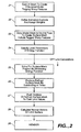
- the main steps in that process are summarized in FIG. 2.
- the first step 21 involves the production of a two dimensional control mesh corresponding to a character to be modeled and animated.
- the mesh shown in FIG. 3, was derived from data scanned in from a physical model of Geri's head.
- the mesh could be created internally through a CAD program without a physical model.
- the set of the control points should be selected so that the chosen primitive representation provides an accurate fit to the original model or design and captures all poses of the character during the animation.
- Geri's head depicted in FIG. 3, the control mesh contains approximately 4100 control points grouped to form approximately 4300 polygon faces. The points were entered manually using a touch probe on a physical model. Much care was taken in selecting the control points. Regions with fine scale details require more control points, i.e., smaller polygons. In addition, regions with larger polygons -- greater spaced control points -- should not directly abut regions of small polygons, instead, to prevent artifacts in the rendered image the number and position of control points should be chosen so that transitions between regions of high and low detail (i.e., little and big polygons) are smooth.
- Control points are stored as a list which includes an identifier and the three dimensional coordinates for each point. Points are grouped as polygons and stored in another list with a polygon identifier and the identifiers of the included points. Sharp features are also stored as ordered lists of vertices and sharpness values.
- the articulation engineer must determine how each point is to move for each gesture or character movement.
- This step 22 is done by coding animation controls, which effectuate transformations of the model corresponding to different movements, e.g., jaw down, or left eyebrow up.
- the transformations may be either linear displacements or, as in the "jaw down" control, rotation about a specified axis.
- the magnitude of the control, i.e., the amount of displacement or angle of rotation is specified by a scalar parameter, s, supplied by the animator.
- the corresponding transformation of the model can be written as a function T(s).
- the possible movements of Geri's face are specified using approximately 252 such controls.
- the articulation engineer can specify the relative motion of different control points under a given animation control by assigning weights to the control points.
- each of the 252 animation controls affects the motion of approximately 150 control points to which non-zero weights are assigned.
- the effect of the weight is to specify the "strength" of the transformation at the given point, i.e., the transformation T with strength s at a point with weight w is given by T ( w*s ).
- the weights for a given control can either be assigned individually, control point by control point, or as a smooth scalar field covering the portion of the mesh whose location is altered by the transformation.
- the next step 23 in FIG. 2 is the creation of a second mesh of points, the skin mesh, which will typically be in one-to-one correspondence with the control points of the kinematic head. This need not be the case, however.
- a skin mesh is used with a greater number of control points than are contained in the kinematic head and a projection of the skin points to the kinematic head is defined so that each skin point is "tied" to a unique point on the kinematic head (which need not be a control point).
- Other embodiments may have a skin mesh that is sparser than the underlying kinematic head. In that case, the same projection strategy can be used to tie skin control points to points on the kinematic head.
- the positions of the skin points were determined by copying the kinematic head control points while Geri's face was in the "neutral pose", which was taken to be the expression on the model head when it was scanned in with the touch probe.
- the "neutral pose” defines the equilibrium positions of the skin points, i.e., the position of Geri's features for which his skin mesh control points will exactly match the positions of the control points of the kinematic head.
- the articulation engineer specifies the properties of Geri's skin and the degree to which it is constrained to follow the underlying kinematic head. This is done by specifying the local parameters of an energy function, the extrema of which determine the position of the quasi-static surface, which in the present example is the skin on Geri's head. Though the details of the energy function used to simulate the skin on Geri's head is illustrative, variations are possible and will be readily apparent to those of ordinary skill in the art. The present invention is thus in no way limited to the details of the described implementation.
- the energy function used to model Geri's head takes the form:
- the second term includes contributions from nearest neighbor points which are not connected by an edge, e.g., points across a diagonal in a quadrilateral.
- the three point function E p ( P 1 , P 2 , P 3 ) K p (
- D 1 is the distance in R 3 between P 3 and P 2 in the neutral pose similarly D 2 is the distance between P 2 and P 1 in the neutral pose.
- R p is the value of
- the coefficient K d may either be a constant throughout the mesh or a combination of scalar field values at the four vertices.
- E h ( P s ) K h
- P s is a skin mesh point
- P k is its corresponding point in the kinematic mesh.
- the spring constant K h is generally given by a scalar field associated with either the dynamic skin mesh or underlying kinematic mesh.
- Scalar fields were used at several points in the above described process in order to define smoothly varying parameters on either the kinematic mesh or skin mesh. These include the articulation weights which specify the relative movement of kinematic mesh control points under the different animation control transformations, as well as the various spring constants and other locally variable parameters of the energy function.
- the control point mesh is a polygonal mesh of arbitrary topology, on which one cannot define global surface coordinates and on which there is no "natural” or "intrinsic" smooth local parameterization.
- One aspect of the current invention is a solution to this problem and a method for consistently defining scalar fields on subdivision surfaces, including scalar fields which can be used as "pseudo-coordinates" to perform parametric shading.
- Three exemplary methods for defining smoothly varying scalar fields on arbitrary polygonal meshes which can be consistently mapped through the recursive subdivision process are described below.
- the first method for defining scalar fields is by painting them directly onto the surface mesh.
- an image of a portion of the surface on which the field is to be defined is painted using a standard two-dimensional computer painting program, e.g., Amazon, the intensity of the color applied to the image is chosen to represent the desired magnitude of the scalar field on the corresponding portion of the painted surface, e.g. if one wants the skin of Geri's forehead to more closely follow the movement of his kinematic head than the flesh in his jowls, one would paint his forehead correspondingly darker when "applying" the field giving rise to the parameter k h in the above described energy function.
- the first step in the painting method is to perform a single subdivision of the control point mesh in the region on which one intends to define the scalar field in order to obtain a mesh with only quadrilateral faces, as will always be the case after the first subdivision with Catmull-Clark rules (discussed in detail in the Subdivision section below).
- the faces in the once subdivided mesh are then numbered and separately coordinatized with two dimensional coordinates u and v assigned to each vertex (thus the need for quadrilateral faces).
- the surface is then further subdivided one or more additional times so that the resulting mesh sufficiently approximates the smooth surface limit.
- the u, v, coordinates for each patch are carried through these additional subdivisions and coordinatize new vertices within the faces of the once subdivided mesh.
- the image is then rendered and painted with a two dimensional painting program such that the distribution and intensity of the applied color represents the desired local magnitude of the particular scalar field being defined.
- the painted image is then scanned and patch numbers, u, v, coordinates, and color intensity are stored for each pixel.
- Each patch is then further subdivided until a dense set of points is obtained within each patch including points with u, v coordinates close to those stored for each pixel in the painted image.
- the scanned pixel color intensities are then assigned as target scalar field values to the corresponding points in this further subdivided mesh.
- the second more direct, if less picturesque, method for defining scalar fields is through smoothing.
- One begins by specifying values of the desired field explicitly at some boundary or known points in a region of the mesh and solving for the rest through an iterative relaxation approach constraining the scalar field value of the vertices to be equal to the average of their nearest neighbors.
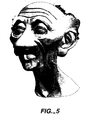
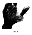
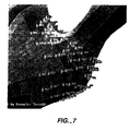
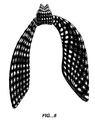
- FIG. 5 shows Geri's face with the k h ("glue" field) shown in red. Smoothing was used in applying the k h field to his chin region. The use of this method to assign smoothly varying articulation weights is illustrated in FIGS. 6 and 7.
- Scalar fields can also be used as pseudo coordinates to enable parameteric shading, e.g., texture and surface mapping.
- parameteric shading e.g., texture and surface mapping.
- One reason that subdivision surfaces have not be more widely adopted for modeling in computer graphics is that the absence of a surface parameterization was thought to prevent the use of texture maps.
- pseudo coordinate fields can only be consistently defined in topologically flat regions of the surface.
- the mapping between the surface in R 3 and the s and t pseudo-coordinate parameterization of the texture sample in R 2 should be at least roughly isometric (i.e. preserve lengths and angles). If one pictures the mapping of the two dimensional texture onto the surface as fitting a rubber sheet over the surface, one wants to minimize the amount of stretching and puckering. If the mapping is onto a portion of the surface with curvature, a pucker free mapping is not possible.
- the aim is to insure that as closely as the geometry allows distances between points measured along the surface embedded in R 3 equal distances measured between the same points in the flat two dimensional s and t pseudo-coordinates of the texture patch for all points on the surface to which the texture mapping is to be applied.
- This energy function can be minimized using Newton's method or other standard numerical technique as described below for minimizing the full energy function to determine the position of skin points.
- the positions of the control points for the surface mesh are determined by minimizing the energy function. This can be done iteratively using Newton's method or other standard numerical technique. For each frame of animation, the location of the skin control points can be taken initially to correspond with the positions of the control points of the kinematic mesh. A quadratic approximation to the energy function is then computed and minimized yielding approximate positions for the control points for the surface mesh. These approximate positions are used in the next quadratic approximation which is solved yielding more refined approximate positions. In practice, a few iterations generally suffice.
- the model can be refined prior to rendering in order to produce a smoother image.
- One method for refining the mesh is through recursive subdivision following the method of Catmull and Clark. See E. Catmull and J. Clark. Recursively generated B-Spline surfaces on arbitrary topological meshes. Computer Aided Design , 10(6):350-355, 1978.
- FIG. 9 shows a region about a vertex in a quadrilateral mesh. This may be either the initial skin mesh or the mesh resulting from one or more subdivisions.
- FIG. 10 shows the same region overlaid with the mesh resulting from a single subdivision.
- the subdivision procedure is applied a finite number of times, depending on the level of detail required of the object which may be specified explicitly or determined automatically as a function of the screen area of the object in a given scene.
- 4 or 5 subdivisions will suffice to produce quadrilateral faces corresponding to a screen area in the rendered image of a small fraction of a pixel. Iterating the above formulas gives the positions and scalar field values for the vertices in the finer subdivided mesh as a function of the positions and scalar field values of the control mesh.
- the vertex points and their scalar field values can be pushed to the infinite iteration smooth surface limit.
- the smooth surface limit is a cubic spline everywhere but in the neighborhoods of the finite number of extraordinary points in the first subdivision of the original mesh.
- a n 1 + cos(2 ⁇ / n) + cos( ⁇ / n ) 2(9 + cos(2 ⁇ / n ) and c 3 is obtained by replacing r i with r i +1 and q i with q i +1 .
- One aspect of the present invention is a method for creating surfaces by sequentially combining different subdivision rules. By subdividing a mesh a finite number of times with one or more sets of "special rules" before taking the infinite subdivision limit with the "standard rules", one can produce different limit surfaces from the same initial mesh. Combining different subdivision rules thus provides an additional degree of freedom which can be a more efficient means for obtaining the desired limit surface than adding points to the initial mesh.
- the problem with using the Hoppe, et al. approach for the realistic animation of characters is that skin surfaces do not have infinitely sharp edges. All real objects, including humans, have some finite radius of curvature along their otherwise sharp features. This fact may be ignored when rendering machined metal objects but is very apparent when modeling and rendering human faces.
- the exemplary embodiment includes a modification of the above described subdivision algorithm to allow the modeling and rendering of edges and creases of arbitrary and continuously variable sharpness.
- FIG. 11 shows a portion of the initial control mesh of Geri's hand with sharp features highlighted.
- care was taken in the initial choice of mesh vertices so that these sharp features lay along edges of the initial mesh.
- Their position in the mesh was stored along with a sharpness value between 0 and 5 (assuming 5 explicit subdivisions was the maximum performed before pushing the vertices to their limits).
- the skin mesh has the same topology as the control mesh, the corresponding edge in the skin mesh is uniquely identified.
- N is an integer
- sharpness 2 features one applies the sharp formulas for the first two subdivisions and then uses the smooth formulas for subsequent subdivision and for taking the smooth surface limit.
- One can calculate the limit values of the sharpness field treating the sharp feature as a subdivision curve and taking its limit value using the dominant left eigenvector as described above for two dimensional surface subdivision. For uniform cubic B-Spline subdivision along a curve, that vector is given by u 1 1/ 6[1,4,1]. See, e.g, E. Stollnitz, T. DeRose and D. Salesin. Wavelets for Computer Graphics , 1996, 61-72. The limit value of the field on a point along the semi-sharp feature is thus given by 2/3 of its value plus one 1/6 of the value of each of its nearest neighbors.
- each vertex point on the semisharp feature is then calculated using the limit value of its sharpness field, i.e., one applies the sharp rules in the neighborhood of that point the number of times specified by the point's sharpness value (including interpolation, as described above for non-integer sharpness values).
- a second application of hybrid subdivision used in the exemplary embodiment involves a modification to the standard Catmull-Clark rules used to determine the location of face points in the first subdivision of a triangular face.
- Catmull-Clark rules used to determine the location of face points in the first subdivision of a triangular face.
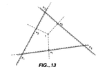
- the shape of the limit surface can be improved if when calculating the location of the face point for a triangular face in the first subdivision (the only time there will be triangular faces), one takes its location to be the average of the locations of its surrounding edge points after subdivision rather than the average of the its surrounding vertices in the undivided mesh, the standard Catmull-Clark rule. This is illustrated in FIG. 13.
- the solid lines and points P i are points in the initial mesh.
Landscapes
- Physics & Mathematics (AREA)
- Engineering & Computer Science (AREA)
- General Physics & Mathematics (AREA)
- Theoretical Computer Science (AREA)
- Computer Graphics (AREA)
- Geometry (AREA)
- Software Systems (AREA)
- Image Generation (AREA)
- Processing Or Creating Images (AREA)
Claims (7)
- Procédé, mis en oeuvre par ordinateur, permettant de spécifier un champ scalaire régulier arbitraire sur un objet graphique modélisé sous forme d'une surface de subdivision définie par un maillage polygonal, ledit maillage polygonal comprenant un ensemble de sommets, ledit champ scalaire étant défini en fonction des positions dudit ensemble de sommets, comprenant les opérations suivantes :définir des valeurs initiales du champ scalaire ;subdiviser ledit maillage polygonal, au moyen d'une règle de subdivision, un nombre suffisant de fois pour obtenir une résolution, ou finesse de définition, voulue pour ledit objet graphique, en établissant des positions de sommets dans un maillage polygonal subdivisé ;comparer ledit champ scalaire existant auxdites positions de sommets dans ledit maillage polygonal subdivisé, où on compare ledit champ scalaire à une surface de subdivision possédant une finesse de définition plus grande que ladite finesse de définition voulue et subdivisée au moyen de ladite règle de subdivision ; avec correction ultérieure desdites valeurs initiales du champ scalaire en cas de divergence ; etrépéter l'opération de comparaison jusqu'à convergence avec un champ scalaire régulier voulu.
- Procédé selon la revendication 1, où ladite surface de subdivision possédant une finesse de définition supérieure à ladite finesse de définition voulue est la surface limite correspondant à une subdivision infinie dudit maillage polygonal.
- Procédé selon la revendication 1 ou 2, où ledit champ scalaire fait fonction d'un paramètre de surface local destiné à être utilisé dans l'ombrage paramétrique dudit objet graphique.
- Procédé selon la revendication 1 ou 2, où ledit champ scalaire spécifie la valeur d'un paramètre cinématique destiné à être utilisé dans l'ordinateur animant ledit objet graphique.
- Procédé selon la revendication 1 ou 2, où ledit champ scalaire spécifie la valeur d'un paramètre dynamique destiné à être utilisé dans l'ordinateur animant ledit objet graphique.
- Procédé selon la revendication 1 ou 2, comprenant en outre l'opération consistant à obtenir par l'opération une résolution itérative la valeur dudit champ scalaire à l'intérieur dudit maillage polygonal soumis à une condition de cohérence.
- Procédé selon la revendication 6, comprenant en outre l'opération consistant à calculer la valeur dudit champ scalaire en des points se trouvant sur ladite surface limite dudit maillage polygonal au moyen des mêmes relations de récursion et de limite utilisées pour déterminer la position de points sur la surface limite.
Priority Applications (1)
| Application Number | Priority Date | Filing Date | Title |
|---|---|---|---|
| EP03013861A EP1933279A2 (fr) | 1997-08-04 | 1998-07-29 | Cartographie de texture et autres utilisations des champs scalaires sur les surfaces de subdivision dans des graphiques et animations informatiques |
Applications Claiming Priority (3)
| Application Number | Priority Date | Filing Date | Title |
|---|---|---|---|
| US08/905,434 US6037949A (en) | 1997-08-04 | 1997-08-04 | Texture mapping and other uses of scalar fields on subdivision surfaces in computer graphics and animation |
| US905434 | 1997-08-04 | ||
| PCT/US1998/015703 WO1999006958A1 (fr) | 1997-08-04 | 1998-07-29 | Texturage et autres utilisations de champs scalaires sur des surfaces de subdivision dans des graphiques et des animations informatiques |
Related Child Applications (1)
| Application Number | Title | Priority Date | Filing Date |
|---|---|---|---|
| EP03013861A Division EP1933279A2 (fr) | 1997-08-04 | 1998-07-29 | Cartographie de texture et autres utilisations des champs scalaires sur les surfaces de subdivision dans des graphiques et animations informatiques |
Publications (2)
| Publication Number | Publication Date |
|---|---|
| EP1000409A1 EP1000409A1 (fr) | 2000-05-17 |
| EP1000409B1 true EP1000409B1 (fr) | 2003-06-18 |
Family
ID=25420807
Family Applications (2)
| Application Number | Title | Priority Date | Filing Date |
|---|---|---|---|
| EP03013861A Withdrawn EP1933279A2 (fr) | 1997-08-04 | 1998-07-29 | Cartographie de texture et autres utilisations des champs scalaires sur les surfaces de subdivision dans des graphiques et animations informatiques |
| EP98938083A Expired - Lifetime EP1000409B1 (fr) | 1997-08-04 | 1998-07-29 | Texturage et autres utilisations de champs scalaires sur des surfaces de subdivision dans des graphiques et des animations informatiques |
Family Applications Before (1)
| Application Number | Title | Priority Date | Filing Date |
|---|---|---|---|
| EP03013861A Withdrawn EP1933279A2 (fr) | 1997-08-04 | 1998-07-29 | Cartographie de texture et autres utilisations des champs scalaires sur les surfaces de subdivision dans des graphiques et animations informatiques |
Country Status (6)
| Country | Link |
|---|---|
| US (1) | US6037949A (fr) |
| EP (2) | EP1933279A2 (fr) |
| AU (1) | AU8668798A (fr) |
| CA (1) | CA2299432C (fr) |
| DE (1) | DE69815687T2 (fr) |
| WO (1) | WO1999006958A1 (fr) |
Cited By (1)
| Publication number | Priority date | Publication date | Assignee | Title |
|---|---|---|---|---|
| US8624893B2 (en) * | 2009-07-31 | 2014-01-07 | Adobe Systems Incorporated | System and method for generating 2D texture coordinates for 3D meshed surfaces |
Families Citing this family (96)
| Publication number | Priority date | Publication date | Assignee | Title |
|---|---|---|---|---|
| CA2239146C (fr) * | 1997-05-30 | 2007-08-07 | Alan D. Ableson | Methode et appareil de determination de la topologie interne a n dimensions d'un systeme a l'interieur d'un espace |
| IT1294492B1 (it) * | 1997-09-16 | 1999-04-12 | Enel Spa | Metodo per la rappresentazione tramite griglia di calcolo semistrutturata di fenomeni fisici estendentisi in un dominio spaziale |
| US6324299B1 (en) * | 1998-04-03 | 2001-11-27 | Cognex Corporation | Object image search using sub-models |
| US6389154B1 (en) * | 1998-07-15 | 2002-05-14 | Silicon Graphics, Inc. | Exact evaluation of subdivision surfaces generalizing box splines at arbitrary parameter values |
| US6307555B1 (en) * | 1998-09-30 | 2001-10-23 | Silicon Graphics, Inc. | Boolean operations for subdivision surfaces |
| US6256038B1 (en) * | 1998-12-10 | 2001-07-03 | The Board Of Trustees Of The Leland Stanford Junior University | Parameterized surface fitting technique having independent control of fitting and parameterization |
| US6553337B1 (en) * | 1998-12-23 | 2003-04-22 | Silicon Graphics, Inc. | Parameterization of subdivision surfaces |
| US6876956B1 (en) * | 1999-08-31 | 2005-04-05 | California Institute Of Technology | Method and system for thin-shell finite-element analysis |
| US6618048B1 (en) | 1999-10-28 | 2003-09-09 | Nintendo Co., Ltd. | 3D graphics rendering system for performing Z value clamping in near-Z range to maximize scene resolution of visually important Z components |
| US6411301B1 (en) | 1999-10-28 | 2002-06-25 | Nintendo Co., Ltd. | Graphics system interface |
| US6452600B1 (en) | 1999-10-28 | 2002-09-17 | Nintendo Co., Ltd. | Graphics system interface |
| US6850638B1 (en) | 2000-02-29 | 2005-02-01 | Alias Systems Corp. | System for naming faces and vertices in an adaptive hierarchical subdivision surface |
| US7098925B1 (en) * | 2000-03-10 | 2006-08-29 | Intel Corporation | Shading of images using texture |
| US6888544B2 (en) * | 2000-03-17 | 2005-05-03 | Hewlett-Packard Development Company, L.P. | Apparatus for and method of rendering 3D objects with parametric texture maps |
| US6539354B1 (en) | 2000-03-24 | 2003-03-25 | Fluent Speech Technologies, Inc. | Methods and devices for producing and using synthetic visual speech based on natural coarticulation |
| US6859862B1 (en) | 2000-04-07 | 2005-02-22 | Nintendo Co., Ltd. | Method and apparatus for software management of on-chip cache |
| US6857061B1 (en) | 2000-04-07 | 2005-02-15 | Nintendo Co., Ltd. | Method and apparatus for obtaining a scalar value directly from a vector register |
| US7119813B1 (en) | 2000-06-02 | 2006-10-10 | Nintendo Co., Ltd. | Variable bit field encoding |
| US6937245B1 (en) | 2000-08-23 | 2005-08-30 | Nintendo Co., Ltd. | Graphics system with embedded frame buffer having reconfigurable pixel formats |
| US6636214B1 (en) | 2000-08-23 | 2003-10-21 | Nintendo Co., Ltd. | Method and apparatus for dynamically reconfiguring the order of hidden surface processing based on rendering mode |
| US7538772B1 (en) | 2000-08-23 | 2009-05-26 | Nintendo Co., Ltd. | Graphics processing system with enhanced memory controller |
| US6639595B1 (en) | 2000-08-23 | 2003-10-28 | Nintendo Co., Ltd. | Achromatic lighting in a graphics system and method |
| US6811489B1 (en) | 2000-08-23 | 2004-11-02 | Nintendo Co., Ltd. | Controller interface for a graphics system |
| US6609977B1 (en) | 2000-08-23 | 2003-08-26 | Nintendo Co., Ltd. | External interfaces for a 3D graphics system |
| US7034828B1 (en) | 2000-08-23 | 2006-04-25 | Nintendo Co., Ltd. | Recirculating shade tree blender for a graphics system |
| US6825851B1 (en) | 2000-08-23 | 2004-11-30 | Nintendo Co., Ltd. | Method and apparatus for environment-mapped bump-mapping in a graphics system |
| US7196710B1 (en) | 2000-08-23 | 2007-03-27 | Nintendo Co., Ltd. | Method and apparatus for buffering graphics data in a graphics system |
| US6867781B1 (en) | 2000-08-23 | 2005-03-15 | Nintendo Co., Ltd. | Graphics pipeline token synchronization |
| US6980218B1 (en) | 2000-08-23 | 2005-12-27 | Nintendo Co., Ltd. | Method and apparatus for efficient generation of texture coordinate displacements for implementing emboss-style bump mapping in a graphics rendering system |
| US6664962B1 (en) | 2000-08-23 | 2003-12-16 | Nintendo Co., Ltd. | Shadow mapping in a low cost graphics system |
| US6999100B1 (en) | 2000-08-23 | 2006-02-14 | Nintendo Co., Ltd. | Method and apparatus for anti-aliasing in a graphics system |
| US6580430B1 (en) | 2000-08-23 | 2003-06-17 | Nintendo Co., Ltd. | Method and apparatus for providing improved fog effects in a graphics system |
| US7184059B1 (en) | 2000-08-23 | 2007-02-27 | Nintendo Co., Ltd. | Graphics system with copy out conversions between embedded frame buffer and main memory |
| US6707458B1 (en) | 2000-08-23 | 2004-03-16 | Nintendo Co., Ltd. | Method and apparatus for texture tiling in a graphics system |
| US6664958B1 (en) | 2000-08-23 | 2003-12-16 | Nintendo Co., Ltd. | Z-texturing |
| US7134960B1 (en) | 2000-08-23 | 2006-11-14 | Nintendo Co., Ltd. | External interfaces for a 3D graphics system |
| US6606689B1 (en) | 2000-08-23 | 2003-08-12 | Nintendo Co., Ltd. | Method and apparatus for pre-caching data in audio memory |
| US6700586B1 (en) | 2000-08-23 | 2004-03-02 | Nintendo Co., Ltd. | Low cost graphics with stitching processing hardware support for skeletal animation |
| US7002591B1 (en) | 2000-08-23 | 2006-02-21 | Nintendo Co., Ltd. | Method and apparatus for interleaved processing of direct and indirect texture coordinates in a graphics system |
| US6587105B1 (en) * | 2000-09-29 | 2003-07-01 | Silicon Graphics, Inc. | Method and computer program product for subdivision generalizing uniform B-spline surfaces of arbitrary degree |
| US6664956B1 (en) | 2000-10-12 | 2003-12-16 | Momentum Bilgisayar, Yazilim, Danismanlik, Ticaret A. S. | Method for generating a personalized 3-D face model |
| US7127081B1 (en) | 2000-10-12 | 2006-10-24 | Momentum Bilgisayar, Yazilim, Danismanlik, Ticaret, A.S. | Method for tracking motion of a face |
| US6731287B1 (en) | 2000-10-12 | 2004-05-04 | Momentum Bilgisayar, Yazilim, Danismanlik, Ticaret A.S. | Method for animating a 3-D model of a face |
| US6697074B2 (en) | 2000-11-28 | 2004-02-24 | Nintendo Co., Ltd. | Graphics system interface |
| US6720962B1 (en) | 2000-12-04 | 2004-04-13 | Joseph Alter Inc. | Hair generation and other natural phenomena with surface derived control volumes in computer graphics and animation |
| US6919906B2 (en) * | 2001-05-08 | 2005-07-19 | Microsoft Corporation | Discontinuity edge overdraw |
| US7286138B2 (en) * | 2001-05-08 | 2007-10-23 | Microsoft Corporation | Discontinuity edge overdraw |
| US7003588B1 (en) | 2001-08-22 | 2006-02-21 | Nintendo Co., Ltd. | Peripheral devices for a video game system |
| JP2005521123A (ja) * | 2001-10-22 | 2005-07-14 | ライカ ミクロジュステムス ヴェツラー ゲーエムベーハー | 光学顕微鏡検出3次元画像の生成方法及び生成装置 |
| US6781583B2 (en) * | 2001-10-31 | 2004-08-24 | Hewlett-Packard Development Company, L.P. | System for generating a synthetic scene |
| US6694264B2 (en) * | 2001-12-19 | 2004-02-17 | Earth Science Associates, Inc. | Method and system for creating irregular three-dimensional polygonal volume models in a three-dimensional geographic information system |
| US20030193503A1 (en) * | 2002-04-10 | 2003-10-16 | Mark Seminatore | Computer animation system and method |
| US8120618B2 (en) * | 2002-06-11 | 2012-02-21 | Hewlett-Packard Development Company, L.P. | System and method for visualization of objects using energy minimization of customized potential functions |
| US7200532B1 (en) * | 2002-06-14 | 2007-04-03 | University Of Kentucky Research Foundation | Subdivision surface-based geometric modeling system |
| US7324116B2 (en) * | 2002-06-20 | 2008-01-29 | Microsoft Corporation | Systems and methods for providing controllable texture sampling |
| US7034824B2 (en) * | 2002-09-17 | 2006-04-25 | Autodesk Canada Co. | System and method for computing a continuous local neighborhood and paramaterization |
| US7617079B2 (en) * | 2003-01-20 | 2009-11-10 | Autodesk, Inc. | Unified subdivision for arbitrary and partial degree surfaces and curves with consistent property propagation |
| US7030884B2 (en) * | 2003-02-13 | 2006-04-18 | Hewlett-Packard Development Company, L.P. | System and method for resampling texture maps |
| US6917369B2 (en) * | 2003-03-25 | 2005-07-12 | Mitsubishi Electric Research Labs, Inc. | Method and apparatus for rendering cell-based distance fields using texture mapping |
| WO2004088468A2 (fr) * | 2003-03-26 | 2004-10-14 | Brigham Young University | Systeme et procede servant a definir des surfaces de t-spline et t-nurcc au moyen d'une methodologie locale evoluee |
| US7009620B2 (en) * | 2003-07-30 | 2006-03-07 | Hewlett-Packard Development Company, L.P. | System and method for combining parametric texture maps |
| US7006103B2 (en) * | 2003-07-30 | 2006-02-28 | Hewlett-Packard Development Company, L.P. | System and method for editing parametric texture maps |
| US7623730B2 (en) * | 2003-07-30 | 2009-11-24 | Hewlett-Packard Development Company, L.P. | System and method that compensate for rotations of textures defined by parametric texture maps |
| US7002592B2 (en) | 2003-07-30 | 2006-02-21 | Hewlett-Packard Development Company, L.P. | Graphical display system and method for applying parametric and non-parametric texture maps to graphical objects |
| US7292247B2 (en) * | 2004-01-26 | 2007-11-06 | Microsoft Corporation | Dynamically determining directions of freedom for control points used to represent graphical objects |
| US7236174B2 (en) * | 2004-01-26 | 2007-06-26 | Microsoft Corporation | Adaptively filtering outlines of typographic characters to simplify representative control data |
| US7136067B2 (en) * | 2004-01-26 | 2006-11-14 | Microsoft Corporation | Using externally parameterizeable constraints in a font-hinting language to synthesize font variants |
| US7187382B2 (en) | 2004-01-26 | 2007-03-06 | Microsoft Corporation | Iteratively solving constraints in a font-hinting language |
| US7352369B2 (en) * | 2004-04-29 | 2008-04-01 | Landmark Graphics Corporation | System and method for approximating an editable surface |
| US7969447B2 (en) * | 2004-05-06 | 2011-06-28 | Pixar | Dynamic wrinkle mapping |
| US9104358B2 (en) | 2004-12-01 | 2015-08-11 | Xerox Corporation | System and method for document production visualization |
| US8687917B2 (en) * | 2005-05-02 | 2014-04-01 | Agency For Science, Technology And Research | Method and apparatus for registration of an atlas to an image |
| US8004517B1 (en) * | 2005-06-24 | 2011-08-23 | Geomagic, Inc. | Methods, apparatus and computer program products that model three-dimensional surface structures |
| US7595799B2 (en) * | 2005-08-04 | 2009-09-29 | Dassault Systemes | Process for creating from a mesh an isotopologic set of parameterized surfaces |
| US7400323B2 (en) * | 2005-08-04 | 2008-07-15 | Dassault Systemes | Process for creating a parametric surface having a required geometrical continuity |
| US9007388B1 (en) | 2006-09-28 | 2015-04-14 | Pixar | Caching attributes of surfaces without global parameterizations |
| US20080117215A1 (en) * | 2006-11-20 | 2008-05-22 | Lucasfilm Entertainment Company Ltd | Providing A Model With Surface Features |
| US8581926B2 (en) * | 2006-12-05 | 2013-11-12 | Luxology, Llc | Systems for advanced editing and rendering of images |
| US8243066B2 (en) * | 2006-12-11 | 2012-08-14 | Richard Garfinkle | System and method for model creation and computer animation |
| US7868885B2 (en) * | 2007-06-22 | 2011-01-11 | Microsoft Corporation | Direct manipulation of subdivision surfaces using a graphics processing unit |
| US8310481B2 (en) * | 2007-10-12 | 2012-11-13 | Edward Ernest Bailey | Computer aided design method for enhancement of local refinement through T-splines |
| US9245371B2 (en) * | 2009-09-11 | 2016-01-26 | Nvidia Corporation | Global stores and atomic operations |
| US8928661B2 (en) | 2011-02-23 | 2015-01-06 | Adobe Systems Incorporated | Representing a field over a triangular mesh |
| US9105116B2 (en) | 2011-09-22 | 2015-08-11 | Xerox Corporation | System and method employing variable size binding elements in virtual rendering of a print production piece |
| US9836868B2 (en) | 2011-09-22 | 2017-12-05 | Xerox Corporation | System and method employing segmented models of binding elements in virtual rendering of a print production piece |
| US20130076731A1 (en) * | 2011-09-22 | 2013-03-28 | Xerox Corporation | System and method employing variable size mechanical binding elements in virtual rendering of a print production piece |
| US9786083B2 (en) | 2011-10-07 | 2017-10-10 | Dreamworks Animation L.L.C. | Multipoint offset sampling deformation |
| EP2660782B1 (fr) | 2012-05-02 | 2019-04-10 | Dassault Systèmes | Conception d'un objet modélisé en 3D |
| US9378579B1 (en) * | 2012-06-27 | 2016-06-28 | Pixar | Creation of cloth surfaces over subdivision meshes from curves |
| CN103400408A (zh) * | 2013-07-29 | 2013-11-20 | 武汉浩翰动画有限公司 | 动漫游戏智能制作与管理系统 |
| US9418465B2 (en) | 2013-12-31 | 2016-08-16 | Dreamworks Animation Llc | Multipoint offset sampling deformation techniques |
| EP3038060B1 (fr) | 2014-12-23 | 2021-09-15 | Dassault Systèmes | Objet modélisé 3D défini par une grille de points de contrôle |
| EP3051446B1 (fr) | 2015-02-02 | 2025-05-21 | Dassault Systèmes | Gravure d'une image 2d sur une surface à subdivision |
| US11225868B1 (en) | 2018-01-31 | 2022-01-18 | Stresswave, Inc. | Method for integral turbine blade repair |
| CN110827409A (zh) * | 2019-10-31 | 2020-02-21 | 江苏理工学院 | 基于最小二乘法的细分曲线曲面的局部形状变形方法 |
| CN115546443B (zh) * | 2022-11-25 | 2023-03-24 | 西南林业大学 | 一种球面六边形格网的局部等距性优化方法和系统 |
Family Cites Families (2)
| Publication number | Priority date | Publication date | Assignee | Title |
|---|---|---|---|---|
| US4912664A (en) * | 1988-02-01 | 1990-03-27 | Mentor Graphics Corporation | Method and apparatus for generating a mesh for finite element analysis |
| WO1995006291A1 (fr) * | 1993-08-27 | 1995-03-02 | Apple Computer, Inc. | Systeme et methode de generation de surfaces splines polynomiales a faible degre lisses sur des mailles irregulieres |
-
1997
- 1997-08-04 US US08/905,434 patent/US6037949A/en not_active Expired - Lifetime
-
1998
- 1998-07-29 EP EP03013861A patent/EP1933279A2/fr not_active Withdrawn
- 1998-07-29 CA CA002299432A patent/CA2299432C/fr not_active Expired - Fee Related
- 1998-07-29 WO PCT/US1998/015703 patent/WO1999006958A1/fr not_active Ceased
- 1998-07-29 DE DE69815687T patent/DE69815687T2/de not_active Expired - Fee Related
- 1998-07-29 EP EP98938083A patent/EP1000409B1/fr not_active Expired - Lifetime
- 1998-07-29 AU AU86687/98A patent/AU8668798A/en not_active Abandoned
Cited By (1)
| Publication number | Priority date | Publication date | Assignee | Title |
|---|---|---|---|---|
| US8624893B2 (en) * | 2009-07-31 | 2014-01-07 | Adobe Systems Incorporated | System and method for generating 2D texture coordinates for 3D meshed surfaces |
Also Published As
| Publication number | Publication date |
|---|---|
| AU8668798A (en) | 1999-02-22 |
| EP1933279A2 (fr) | 2008-06-18 |
| WO1999006958A1 (fr) | 1999-02-11 |
| US6037949A (en) | 2000-03-14 |
| DE69815687T2 (de) | 2004-12-02 |
| DE69815687D1 (de) | 2003-07-24 |
| CA2299432A1 (fr) | 1999-02-11 |
| EP1000409A1 (fr) | 2000-05-17 |
| CA2299432C (fr) | 2006-01-03 |
Similar Documents
| Publication | Publication Date | Title |
|---|---|---|
| EP1000409B1 (fr) | Texturage et autres utilisations de champs scalaires sur des surfaces de subdivision dans des graphiques et des animations informatiques | |
| US6489960B2 (en) | Hybrid subdivision in computer graphics | |
| EP1000411B1 (fr) | Subdivision hybride de graphiques d'ordinateur | |
| US5602979A (en) | System and method for generating smooth low degree polynomial spline surfaces over irregular meshes | |
| Bando et al. | A simple method for modeling wrinkles on human skin | |
| US5796400A (en) | Volume-based free form deformation weighting | |
| Loop et al. | Approximating subdivision surfaces with Gregory patches for hardware tessellation | |
| DiPaola | Extending the range of facial types | |
| US7570264B2 (en) | Rig baking | |
| US20070247458A1 (en) | Adaptive computation of subdivision surfaces | |
| Sheffer et al. | Smoothing an overlay grid to minimize linear distortion in texture mapping | |
| EP1097435B1 (fr) | Evaluation parametrique de surfaces dans un espace vrai de matrice de subdivision d'un carreau irregulier | |
| JP2009521062A (ja) | 二次元画像のシェーディングによる対象物の三次元形状のモデル化 | |
| Ni et al. | Efficient substitutes for subdivision surfaces | |
| Loviscach | Wrinkling coarse meshes on the GPU | |
| Sauvage et al. | Length constrained multiresolution deformation for surface wrinkling | |
| Kuriyama et al. | Discrete parameterization for deforming arbitrary meshes | |
| Stalpers et al. | Deforming geometric models based on a polygonal skeleton mesh | |
| Michalik et al. | A constraint-based method for sculpting free-form surfaces | |
| Owada et al. | Volume Painter: Geometry-Guided Volume Modeling by Sketching on the Cross-Section. | |
| Lin et al. | A feature-adaptive subdivision method for real-time 3D reconstruction of repeated topology surfaces | |
| Tversky | Using Texture Mapping and WYSIWYG Painting to Create Geometric Tools | |
| Ma et al. | Texture Synthesis on Subdivision Surfaces | |
| Schein | Trivariate Functions in Solid Modeling, Medical Imaging and Computer Graphics | |
| Lee | Multiresolution surface parametrization and applications |
Legal Events
| Date | Code | Title | Description |
|---|---|---|---|
| PUAI | Public reference made under article 153(3) epc to a published international application that has entered the european phase |
Free format text: ORIGINAL CODE: 0009012 |
|
| 17P | Request for examination filed |
Effective date: 20000228 |
|
| AK | Designated contracting states |
Kind code of ref document: A1 Designated state(s): DE FR GB IT NL |
|
| RIN1 | Information on inventor provided before grant (corrected) |
Inventor name: TRUONG, TIEN, GIA Inventor name: KASS, MICHAEL Inventor name: DEROSE, ANTHONY, DAVID |
|
| 17Q | First examination report despatched |
Effective date: 20010516 |
|
| GRAH | Despatch of communication of intention to grant a patent |
Free format text: ORIGINAL CODE: EPIDOS IGRA |
|
| GRAH | Despatch of communication of intention to grant a patent |
Free format text: ORIGINAL CODE: EPIDOS IGRA |
|
| GRAA | (expected) grant |
Free format text: ORIGINAL CODE: 0009210 |
|
| AK | Designated contracting states |
Designated state(s): DE FR GB IT NL |
|
| REG | Reference to a national code |
Ref country code: GB Ref legal event code: FG4D |
|
| REF | Corresponds to: |
Ref document number: 69815687 Country of ref document: DE Date of ref document: 20030724 Kind code of ref document: P |
|
| PLBE | No opposition filed within time limit |
Free format text: ORIGINAL CODE: 0009261 |
|
| STAA | Information on the status of an ep patent application or granted ep patent |
Free format text: STATUS: NO OPPOSITION FILED WITHIN TIME LIMIT |
|
| ET | Fr: translation filed | ||
| 26N | No opposition filed |
Effective date: 20040319 |
|
| NLT1 | Nl: modifications of names registered in virtue of documents presented to the patent office pursuant to art. 16 a, paragraph 1 |
Owner name: PIXAR |
|
| REG | Reference to a national code |
Ref country code: FR Ref legal event code: CD Ref country code: FR Ref legal event code: CA |
|
| PGFP | Annual fee paid to national office [announced via postgrant information from national office to epo] |
Ref country code: DE Payment date: 20080731 Year of fee payment: 11 |
|
| PGFP | Annual fee paid to national office [announced via postgrant information from national office to epo] |
Ref country code: NL Payment date: 20080619 Year of fee payment: 11 Ref country code: IT Payment date: 20080718 Year of fee payment: 11 Ref country code: FR Payment date: 20080618 Year of fee payment: 11 |
|
| PGFP | Annual fee paid to national office [announced via postgrant information from national office to epo] |
Ref country code: GB Payment date: 20090612 Year of fee payment: 12 |
|
| NLV4 | Nl: lapsed or anulled due to non-payment of the annual fee |
Effective date: 20100201 |
|
| PG25 | Lapsed in a contracting state [announced via postgrant information from national office to epo] |
Ref country code: DE Free format text: LAPSE BECAUSE OF NON-PAYMENT OF DUE FEES Effective date: 20100202 |
|
| GBPC | Gb: european patent ceased through non-payment of renewal fee |
Effective date: 20100729 |
|
| PG25 | Lapsed in a contracting state [announced via postgrant information from national office to epo] |
Ref country code: IT Free format text: LAPSE BECAUSE OF NON-PAYMENT OF DUE FEES Effective date: 20090729 |
|
| REG | Reference to a national code |
Ref country code: FR Ref legal event code: ST Effective date: 20110531 |
|
| PG25 | Lapsed in a contracting state [announced via postgrant information from national office to epo] |
Ref country code: FR Free format text: LAPSE BECAUSE OF NON-PAYMENT OF DUE FEES Effective date: 20090731 Ref country code: GB Free format text: LAPSE BECAUSE OF NON-PAYMENT OF DUE FEES Effective date: 20100729 |
|
| PG25 | Lapsed in a contracting state [announced via postgrant information from national office to epo] |
Ref country code: NL Free format text: LAPSE BECAUSE OF NON-PAYMENT OF DUE FEES Effective date: 20100201 |