EP1000430B1 - Kupplungsvorrichtung zwischen zwei modularen elektrischen element - Google Patents
Kupplungsvorrichtung zwischen zwei modularen elektrischen element Download PDFInfo
- Publication number
- EP1000430B1 EP1000430B1 EP98928401A EP98928401A EP1000430B1 EP 1000430 B1 EP1000430 B1 EP 1000430B1 EP 98928401 A EP98928401 A EP 98928401A EP 98928401 A EP98928401 A EP 98928401A EP 1000430 B1 EP1000430 B1 EP 1000430B1
- Authority
- EP
- European Patent Office
- Prior art keywords
- slide member
- mechanical coupling
- block according
- cover
- electrical block
- Prior art date
- Legal status (The legal status is an assumption and is not a legal conclusion. Google has not performed a legal analysis and makes no representation as to the accuracy of the status listed.)
- Expired - Lifetime
Links
- 230000008878 coupling Effects 0.000 title claims abstract description 55
- 238000010168 coupling process Methods 0.000 title claims abstract description 55
- 238000005859 coupling reaction Methods 0.000 title claims abstract description 55
- 239000004020 conductor Substances 0.000 claims abstract description 29
- 230000000873 masking effect Effects 0.000 claims description 6
- 238000003780 insertion Methods 0.000 claims description 5
- 230000037431 insertion Effects 0.000 claims description 5
- 238000001514 detection method Methods 0.000 claims description 3
- 230000001681 protective effect Effects 0.000 claims description 2
- 230000002035 prolonged effect Effects 0.000 claims 1
- 230000002401 inhibitory effect Effects 0.000 description 2
- 230000005226 mechanical processes and functions Effects 0.000 description 2
- 230000003042 antagnostic effect Effects 0.000 description 1
- 230000000903 blocking effect Effects 0.000 description 1
- 238000005352 clarification Methods 0.000 description 1
- 230000001419 dependent effect Effects 0.000 description 1
- 238000006073 displacement reaction Methods 0.000 description 1
- 238000010494 dissociation reaction Methods 0.000 description 1
- 230000005593 dissociations Effects 0.000 description 1
- 238000000605 extraction Methods 0.000 description 1
- 238000009434 installation Methods 0.000 description 1
- 230000013011 mating Effects 0.000 description 1
- 210000000056 organ Anatomy 0.000 description 1
- 230000000149 penetrating effect Effects 0.000 description 1
- 230000000284 resting effect Effects 0.000 description 1
- 230000001131 transforming effect Effects 0.000 description 1
- 238000003466 welding Methods 0.000 description 1
Images




Classifications
-
- H—ELECTRICITY
- H01—ELECTRIC ELEMENTS
- H01H—ELECTRIC SWITCHES; RELAYS; SELECTORS; EMERGENCY PROTECTIVE DEVICES
- H01H83/00—Protective switches, e.g. circuit-breaking switches, or protective relays operated by abnormal electrical conditions otherwise than solely by excess current
- H01H83/20—Protective switches, e.g. circuit-breaking switches, or protective relays operated by abnormal electrical conditions otherwise than solely by excess current operated by excess current as well as by some other abnormal electrical condition
- H01H83/22—Protective switches, e.g. circuit-breaking switches, or protective relays operated by abnormal electrical conditions otherwise than solely by excess current operated by excess current as well as by some other abnormal electrical condition the other condition being imbalance of two or more currents or voltages
- H01H83/226—Protective switches, e.g. circuit-breaking switches, or protective relays operated by abnormal electrical conditions otherwise than solely by excess current operated by excess current as well as by some other abnormal electrical condition the other condition being imbalance of two or more currents or voltages with differential transformer
-
- H—ELECTRICITY
- H01—ELECTRIC ELEMENTS
- H01H—ELECTRIC SWITCHES; RELAYS; SELECTORS; EMERGENCY PROTECTIVE DEVICES
- H01H71/00—Details of the protective switches or relays covered by groups H01H73/00 - H01H83/00
- H01H71/08—Terminals; Connections
- H01H71/082—Connections between juxtaposed circuit breakers
-
- H—ELECTRICITY
- H01—ELECTRIC ELEMENTS
- H01H—ELECTRIC SWITCHES; RELAYS; SELECTORS; EMERGENCY PROTECTIVE DEVICES
- H01H71/00—Details of the protective switches or relays covered by groups H01H73/00 - H01H83/00
- H01H71/02—Housings; Casings; Bases; Mountings
- H01H71/0207—Mounting or assembling the different parts of the circuit breaker
- H01H2071/0242—Assembling parts of a circuit breaker by using snap mounting techniques
-
- H—ELECTRICITY
- H01—ELECTRIC ELEMENTS
- H01H—ELECTRIC SWITCHES; RELAYS; SELECTORS; EMERGENCY PROTECTIVE DEVICES
- H01H2300/00—Orthogonal indexing scheme relating to electric switches, relays, selectors or emergency protective devices covered by H01H
- H01H2300/044—Application rejection 1: coded interacting surfaces, polarising, e.g. to avoid insertion of a circuit breaker or fuse or relay or rating plug of the wrong caliber or in the wrong direction
-
- H—ELECTRICITY
- H01—ELECTRIC ELEMENTS
- H01H—ELECTRIC SWITCHES; RELAYS; SELECTORS; EMERGENCY PROTECTIVE DEVICES
- H01H71/00—Details of the protective switches or relays covered by groups H01H73/00 - H01H83/00
- H01H71/10—Operating or release mechanisms
- H01H71/1009—Interconnected mechanisms
- H01H71/1018—Interconnected mechanisms with only external interconnections
-
- H—ELECTRICITY
- H01—ELECTRIC ELEMENTS
- H01H—ELECTRIC SWITCHES; RELAYS; SELECTORS; EMERGENCY PROTECTIVE DEVICES
- H01H9/00—Details of switching devices, not covered by groups H01H1/00 - H01H7/00
- H01H9/02—Bases, casings, or covers
- H01H9/0264—Protective covers for terminals
Definitions
- the present invention relates to an electrical block consisting of two modular type elements contiguous to one of their side walls and having fastening means keeping them in contact with each other in this configuration.
- This interpenetration is done on two perpendicular axes without said members attached to one of the elements and penetrating the volume of the other is generally provided with a degree of freedom to make the junction first on an axis, then on the other.
- the electrician in charge of the assembly uses, in order to join the two elements, the games at his disposal, such as the lateral games that remain when the rigid conductors are inserted into the connection terminals.
- the displacement of the sliding member is normally intended to separate the ends of the rigid conductors of the volume potentially occupied by the breaker to be joined, so that they do not interfere with the movement to bring the two elements in contact with the one of the other, a movement which develops in a direction perpendicular to the direction of connection of said ends in their terminals.
- the present invention overcomes these limitations, and further proposes a complete solution to the problem of double coupling along two non-collinear axes.
- the recommended solution proves more economically interesting, and it greatly improves the reliability, because it eliminates including any welding between mobile elements and fixed elements.
- a major objective of the invention is finally to propose, simultaneously with the sequential realization of said couplings, the mutual attachment of the contiguous elements, which must in any case be performed by the electrician responsible for assembly.
- the electric power and control members of the element comprising the sliding drawer including the connection terminals and all the conductors, are dissociated from the members performing the mechanical coupling, and animated by a movement relative when the sliding drawer is in motion
- the dissociation carried out makes it possible to ensure the sliding in all circumstances.
- the drawer actuates, when it arrives in the vicinity of the position in abutment, said conductors then being housed in the terminals of the other element, fixing means to the latter.
- these fixing means consist of at least one hook belonging to the element housing the sliding drawer, being able to pivot outwardly in the vicinity of the edge of its lateral facade situated opposite the orifice of insertion of said drawer, so as to penetrate into at least one recess provided for this purpose in the second element, as well as in at least one centering tab integral with the drawer and able to penetrate in the vicinity of said insertion hole of the drawer in at least one corresponding housing of the other element, the directions of insertion of the hook and the tab being opposite.
- the sliding translational movement of the drawer is then transformed into a rotary movement of a part integral with the element housing the drawer.
- the sliding part must be movable along the axis of the mechanical coupling.
- the sliding member is movable in a direction parallel to that of the mechanical coupling, the electric power and control members of the element comprising said sliding member, including the terminals of connection and all of the conductors, being dissociated from the members performing the mechanical coupling by the sliding member, and animated relative movement when the latter is in motion.
- this sliding member consists of a portion of the cover of one of the two contiguous elements, to which are secured the parts performing the mechanical coupling which can be moved between two extreme positions, a position in which they do not cross the plane of the lateral side of attachment of the element on which the sliding part of the cover moves, and a position in which they can exert their mechanical coupling.
- said sliding portion of the cover can actuate, when it arrives in the vicinity of the mechanical coupling exercise position, fastening means to the other element.
- the attachment between the two contiguous elements is preferably antagonistic on two opposite sides of the block, by inserting male elements in housings in which they are adjusted, hence a blocking along the three axes .
- the first element is a differential block, the second element being a circuit breaker.
- the sliding member equips the differential block and is composed of a drawer in which are mounted the connection terminals, the detection torus and the conductors of control and power, as well as a lateral wing developing parallel to the sides provided with connection terminals of the differential block and the circuit breaker attached thereto, said wing comprising the connecting conductors of the two elements, the ends of which parallel outwards to the sliding axis of the drawer.
- This drawer is movable between two extreme positions, a closed position in which the ends of the conductors protruding from the aforementioned wing are housed in the connection terminals of the circuit breaker, and an open position in which said ends are disengaged from said terminals.
- the part of the drawer comprising the connection terminals of the differential block and the lateral wing are covered with a protective cover masking said terminals and leaving free access for tightening / loosening, and covering the conductors housed in said wing.
- This cover has a cover located on the drawer, masking the components of the differential block in the open position of the drawer.
- said cover includes a terminal cover located at the side wing, and for protecting access to the clamping members of the circuit breaker.
- this terminal cover is slidable in a housing of the cover between a storage position and an extended position, in which the shape of the housing allows it to rotate axis parallel to the mechanical coupling direction, between said deployed position and a rest position masking the connection terminals of the circuit breaker.
- the differential block comprises for this purpose a tab connected to a pivoting shaft comprising two hooks, the assembly being disposed at the edge opposite the sliding opening of the slide on the internal face of the lateral side contiguous to the circuit breaker, said tab cooperating with the inner end of the drawer for rotating said hooks.
- said tab is integral in rotation with said shaft, and fits into a housing disposed at the inner end of the drawer, via an opening whose edges perpendicular to the bottom of the drawer exert an alternative action on the tab, aimed at him. communicate a rotational movement in both directions.
- this tab is a bent lever whose faces perpendicular to the bottom of the drawer allow said edges of the opening of the housing to perform a relative movement along said faces, transforming the slide of the drawer into a rotation of the leg and the tree supporting the hooks.
- the lateral wing protruding from the sliding drawer comprises centralizers developing parallel to the axis of sliding in the direction of the terminals of the circuit breaker, in which there are provided housing adapted to receive said centralizers.
- the sliding member is a part of the differential block cover comprising the lock of said block, the drive lever of the lock of the circuit breaker, and centering pins acting in the direction mechanical coupling.
- the coupling is therefore performed at several points, which ensures perfect alignment of the two elements forming the electrical block, alignment of the remaining necessary for the mounting of the block on the rail can be done in good conditions.
- the differential block may comprise a keying protrusion developing in the direction of the mechanical coupling and cooperating with a corresponding aperture of the circuit breaker, said keying protrusion being also integral with the sliding portion of the cover.
- the standard requires that the two elements forming the electrical block described be finally locked to one another, so that it is no longer possible to separate them without destroying a visible zone proving the intention to dissociate them.
- the element comprising the sliding member is provided with a locking button inhibiting, when actuated, the sliding of said member, said button being operable once in one direction only.
- the differential block which comprises a pusher, which slides there perpendicularly to the two directions of the electrical and mechanical couplings, said pusher, accessible from the cover of the differential block, being extended in the sliding direction by a rod adapted to fit in a housing provided for this purpose in the sliding drawer, and inhibiting any movement thereof, said pusher then flush with the hood and can no longer be operated after adjustment of the end of the rod in said housing.
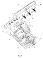
- the differential block (B) is shown coupled to a circuit breaker (D) in this case four-pole.
- D circuit breaker
- the differential block comprises a control lever (1) of a trigger lock (not visible) mechanically connected to the locks of the circuit breaker (D), also controllable via the levers (2): this mechanical connection forms the essential part of the mechanical coupling.
- connection terminals of the differential block (B) are hidden by the cover (3) of the drawer (4), of which only the face located in the extension of the outer planar face of the lateral flange (5) is visible.
- the part of the cover (3a) assigned to said wing (5) comprises a terminal cover (6) resting on the upper part of the connection terminals (not visible) of the circuit breaker (D).
- Figure 2 shows more clearly the sliding drawer (4) and its lateral flange (5), covered with the lid (3, 3a).
- the spool (4) is in the extended position, and the connection terminals (7) of the differential block (B) are therefore kept at a distance from the body of said block (B) since they are integral with them, but always accessible via orifices. (8) made in the upper part of the lid (3).
- the portion of the cover (3a) surmounting the lateral flange (5) comprises a device for storing the terminal cover (6), composed of two complexly-shaped side rails (9a, 9b), rectilinear grooves allowing first a translating upwards said terminal cover, then staggered hard points allowing a rotation thereof to fold in the position shown in Figure 1. It is a kind of an extension of the cover (3) to cover the circuit breaker terminals (D).
- This figure 2 also specifies some of the elements of the mechanical coupling: the lock of the trigger block (B), when actuated, moves a leg or lever (10) which in turn triggers the latching of the four-pole circuit breaker (D) .
- This lug is housed in a hole equipping the side wall of the circuit breaker (D), whose shape allows a movement of the lug (10) when an operating problem occurs.
- the side wall (P) of the differential block (B) comprises centering pins (11), only one of which is visible here, and a pin of keying (12) for associating components of compatible size.
- Figure 2 shows the fasteners hooks (13) pivotally connected to the differential block (B) and can be inserted in corresponding holes of the circuit breaker (D) to engage their side.
- cover (3) and its flange (3a) cover parts whose contact can be dangerous, namely respectively the terminals (7) of the differential block (B) and the rigid conductors whose ends exit perpendicularly to the apparent crenellations in the two figures.
- the spool (4) has all the power and control part of the electrical circuit, namely mainly said terminals (7), the rigid conductors (25) connecting the circuit breaker (D) and torus (16) through which they pass. .
- the control part, the "secondary" wound around the torus, consists of fine, flexible son, which do not alter the mechanical function.
- the upper part of the half-shell (15) comprises the control lever (1) disposed above the lock (not shown).
- the end of the slide (4) cooperates with a tab (17) controlling the movement of the pivoting hooks (13).
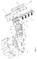
- the design of the leg (17) / hook (13) assembly and its mechanical connection to the half-shell (15) appear more clearly in FIGS. 5 and 6, whereas the elements of the lateral mechanical coupling are better represented in FIG. 4, with the centering pins (11) and keying (12), and the lug (10) integral with the lock.
- the tab (17) is inserted into a housing (18) of the drawer (4), having an opening (19) limited by two columns (20, 20 ').
- the latter slide along the faces of the lug (17) when the drawer is driven in a sliding movement, causing said lug (17) which pivots in same time as the shaft (21) around an axis adjacent the edge of the differential block.
- the hooks (13), being themselves integral with said shaft (21), pivot at the same time, and are in the fixing position when the drawer (4) is in internal abutment.
- FIG. 5 further shows the centralizers (22) which cooperate with orifices (23) located under the terminals of the circuit breaker (see FIG. 2).
- the centralizers (22) and the hooks (13) move in opposite directions relative to the circuit-breaker box (D), ensuring a firm fastening of the elements forming the compact electric block of the invention.
- This pusher (26) is extended by a rod (27) which can be housed in the housing (24) when the pusher (26) is actuated. In this case, the pusher (26) is flush with the surface of the cover of the differential block (B) and it is no longer possible to reassemble it without breaking something on the housing of said block (B).
- This pusher (26) appears in particular in Figure 9, prominent with respect to the cover (28) because it has not been actuated.
- FIG. 9 illustrates the second variant of the invention, with a sliding member actuated in the direction of the mechanical coupling.
- the invention may, in general, also be applied to other elements of the modular type, such as timers, remote switches, etc.
Landscapes
- Engineering & Computer Science (AREA)
- Power Engineering (AREA)
- Switch Cases, Indication, And Locking (AREA)
- Trip Switchboards (AREA)
- Coupling Device And Connection With Printed Circuit (AREA)
- Breakers (AREA)
Claims (21)
- Kompakter elektrischer Block, der aus zwei Elementen (D, P) des modularen Typs zusammengesetzt ist, die jeweils längs einer ihrer Seitenflächen aneinander geklebt sind und Befestigungsmittel aufweisen, die sie in dieser Konfiguration in gegenseitigem Kontakt halten, was eine doppelte Zusammenwirkung ermöglicht:- mechanisch über eine mechanische Kopplung, die über eine zu der Ebene der Seitenfläche senkrechte Richtung und längs dieser wirkt, und- elektrisch über eine Zwischenverbindung, die in einer Richtung senkrecht zu jener der mechanischen Kopplung hergestellt ist,wobei eines der Elemente (P) ein Schubfach (4), das senkrecht zu der mechanischen Kopplung gleitet, aufweist, um die elektrische Verbindung zu schaffen,
dadurch gekennzeichnet, dass die elektrischen Leistungs- und Steuerorgane (7, 25, 16) des Elements (P) einschließlich der Verbindungsanschlüsse (7) und der Gesamtheit der Leiter (25) von den Organen (10, 11, 12), die die mechanische Kopplung schaffen, getrennt sind und in eine relative Bewegung versetzt werden, wenn das Gleitschubfach (4) in Bewegung ist. - Kompakter elektrischer Block nach dem vorhergehenden Anspruch, dadurch gekennzeichnet, dass das Schubfach (4) dann, wenn es in der Nähe der inneren Anschlagposition ankommt, in der sich die Leiter (25) in den Anschlüssen des anderen Elements (D) befinden, Mittel (13) für die Befestigung an diesem letzteren betätigt.
- Kompakter elektrischer Block nach dem vorhergehenden Anspruch, dadurch gekennzeichnet, dass die Befestigungsmittel bestehen aus wenigstens einem Haken (13), der zu dem das gleitende Schubfach (4) aufnehmenden Element (P) gehört und daran nach außen in die Nähe der Kante seiner Seitenfläche schwenken kann, die sich gegenüber der Einschuböffnung des Schubfachs (4) befindet, so dass er in wenigstens eine hierzu in dem zweiten Element (D) vorgesehene Aussparung eindringen kann, und aus wenigstens einem Zentrierungsansatz (22), der mit dem gleitenden Schubfach (4) fest verbunden ist und in der Umgebung der Einschuböffnung des Schubfachs (4) in wenigstens einen Aufnahmesitz (23) eindringen kann, der dem anderen Element (D) entspricht, wobei die Einschubrichtung des Hakens (13) und des Ansatzes (22) entgegengesetzt sind.
- Kompakter elektrischer Block, der aus zwei Elementen (D, P) des modularen Typs zusammengesetzt ist, die längs einer ihrer Seitenflächen aneinander geklebt sind und Befestigungsmittel aufweisen, die sie in dieser gegenseitigen Konfiguration in gegenseitigem Kontakt halten, was eine doppelte Zusammenwirkung ermöglicht:- mechanisch über eine mechanische Kopplung, die über eine zu der Ebene der Seitenflächen senkrechte Richtung und längs dieser wirkt, und- elektrisch über eine Zwischenverbindung, die in einer Richtung senkrecht zu jener der mechanischen Kopplung hergestellt ist,wobei eines der Elemente (P) ein gleitendes Organ (28) umfasst, dadurch gekennzeichnet, dass das gleitende Organ (28) in einer Richtung parallel zu jener der mechanischen Kopplung beweglich ist, wobei die elektrischen Leistungs- und Steuerorgane (7, 25, 16) des Elements (P) einschließlich der Verbindungsanschlüsse (7) und der Gesamtheit der Leiter (25) von den Organen (10, 11, 12), die die mechanische Kopplung über das gleitende Organ (28) verwirklichen, getrennt sind und in eine relative Bewegung versetzt werden, wenn dieses letztere in Bewegung ist.
- Kompakter elektrischer Block nach Anspruch 4, dadurch gekennzeichnet, dass das gleitende Organ (28) aus einem Teil der Abdeckhaube eines der zwei aneinander geklebten Elemente (P) besteht, mit dem die Teile (10, 11, 12) fest verbunden sind, die die mechanische Kopplung verwirklichen und zwischen zwei Extrempositionen verlagert werden können, nämlich einer Position, in der sie die Ebene der Klebeseitenfläche des Elements (P), an dem sich der gleitende Teil der Abdeckhaube (28) verlagert, nicht durchqueren, und einer Position, in der sie ihre mechanische Kopplung ausüben können.
- Kompakter elektrischer Block nach dem vorhergehenden Anspruch, dadurch gekennzeichnet, dass der gleitende Teil der Abdeckhaube dann, wenn er in der Umgebung der Position für die Ausübung der mechanischen Kopplung ankommt, Mittel für die Befestigung am anderen Element (D) betätigt.
- Kompakter elektrischer Block nach einem der vorhergehenden Ansprüche, dadurch gekennzeichnet, dass das erste Element ein differentieller Block (P) ist, während das zweite Element ein Trennschalter (D) ist.
- Kompakter elektrischer Block nach dem vorhergehenden Anspruch, dadurch gekennzeichnet, dass der differentielle Block (P) mit dem gleitenden Organ ausgerüstet ist und aus einem Schubfach (4), in dem die Verbindungsanschlüsse (7), der Erfassungstoroid (16) und die Steuer- und Leistungsleiter (25) angebracht sind, sowie aus einem Seitenflügel (5), der sich parallel zu den mit den Verbindungsanschlüssen (7) des differentiellen Blocks (P) und des an ihm befestigten Trennschalters (D) versehenen Seiten erstreckt, aufgebaut ist, wobei der Flügel (5) die Leiter (25) für die Verbindung der zwei Elemente (P, D) aufweist, deren Enden hiervon parallel zur Gleitachse des Schubfachs (4) vorstehen.
- Kompakter elektrischer Block nach dem vorhergehenden Anspruch, dadurch gekennzeichnet, dass das Schubfach (4) zwischen zwei Extrempositionen beweglich ist, einer Schließposition, in der sich die Enden der Leiter (25), die von dem Flügel (5) vorstehen, in den Verbindungsanschlüssen des Trennschalters (D) befinden, und einer Öffnungsposition, in der diese Enden von diesen Anschlüssen gelöst sind.
- Kompakter elektrischer Block nach einem der Ansprüche 8 und 9, dadurch gekennzeichnet, dass jener Teil des Schubfachs, der die Verbindungsanschlüsse (7) des differentiellen Blocks (P) und den Seitenflügel (5) enthält, mit einem Schutzdeckel (3, 3a) abgedeckt ist, der die Anschlüsse (7) verbirgt und einen freien Zugang (8) für die Festklemmung/Klemmlösung freilässt und die in diesem Flügel (5) befindlichen Leiter (25) abdeckt.
- Kompakter elektrischer Block nach dem vorhergehenden Anspruch, dadurch gekennzeichnet, dass der Deckel (3, 3a) eine Abdeckung (30) aufweist, die sich auf dem Schubfach (4) befindet und die Komponenten (16, 25) des differentiellen Blocks (P) in der Öffnungsposition des Schubfachs (4) verbergen.
- Kompakter elektrischer Block nach einem der Ansprüche 10 und 11, dadurch gekennzeichnet, dass der Deckel (3, 3a) eine Anschlussabdeckung (6) umfasst, die sich auf Höhe des Seitenflügels (5) befindet und dazu vorgesehen ist, den Zugang zu den Klemmorganen des Trennschalters (D) zu schützen.
- Kompakter elektrischer Block nach dem vorhergehenden Anspruch, dadurch gekennzeichnet, dass die Anschlussabdeckung (6) in einem Aufnahmesitz (9, 9a) des Deckels zwischen einer Anordnungsposition und einer ausgefahrenen Position gleiten kann, in der die Form des Aufnahmesitzes (9, 9a) ihr eine Drehung um eine zur Richtung der mechanischen Kopplung parallele Achse zwischen der ausgefahrenen Position und einer Ruheposition, in der sie die Verbindungsanschlüsse des Trennschalters (D) verbirgt, ermöglicht.
- Kompakter elektrischer Block nach einem der Ansprüche 8 bis 13, dadurch gekennzeichnet, dass der differentielle Block (P) einen Ansatz (17) aufweist, der mit einer Schwenkwelle (21) verbunden ist, die zwei Haken (13) umfasst, wobei die Gesamtheit auf Höhe der Kante gegenüber der Gleitöffnung des Schubfachs (4) auf der inneren Fläche der an den Trennschalter (D) angeklebten Seitenfläche angeordnet ist, wobei der Ansatz (17) mit dem inneren Ende des Schubfachs (4) zusammenwirkt, um die Haken (13) rotatorisch zu bewegen.
- Kompakter elektrischer Block nach dem vorhergehenden Anspruch, dadurch gekennzeichnet, dass der Ansatz (17) mit der Welle (21) drehfest verbunden ist und in einen Aufnahmesitz (18), der am inneren Ende des Schubfachs (4) angeordnet ist, durch eine Öffnung (19) eingeschoben ist, deren Ränder (20, 20') senkrecht zum Boden des Schubfachs (4) auf den Ansatz (17) eine hin und her gehenden Wirkung ausüben, die darauf zielt, ihm eine Drehbewegung in den beiden Richtungen zu verleihen.
- Kompakter elektrischer Block nach dem vorhergehende Anspruch, dadurch gekennzeichnet, dass der Ansatz (17) ein gebogener Hebel ist, dessen zum Boden des Schubfachs (4) senkrechte Seiten den Kanten (20, 20') der Öffnung (19) des Aufnahmesitzes (18) ermöglichen, eine relative Bewegung längs dieser Seiten auszuführen, wodurch die Gleitbewegung des Schubfachs (4) in eine Drehung des Ansatzes (17) und der die Haken (13) unterstützenden Welle (21) überführt wird.
- Kompakter elektrischer Block nach einem der Ansprüche 8 bis 16, dadurch gekennzeichnet, dass der von dem gleitenden Schubfach (4) vorstehende Seitenflügel (5) Zentriereinrichtungen (22) aufweist, die parallel zur Gleitachse in Richtung der Anschlüsse des Trennschalters (D) verlaufen, unter denen Aufnahmesitze (23) vorgesehen sind, die diese Zentriereinrichtungen (22) aufnehmen können.
- Kompakter elektrischer Block nach Anspruch 7, dadurch gekennzeichnet, dass das Gleitorgan (28) ein Teil einer Abdeckhaube des differentiellen Blocks (P) ist, der das Schloss des Blocks (P), den Antriebshebel (10) des Schlosses des Trennschalters (D) und die Zentrierungszähne (11), die in Richtung der mechanischen Kopplung wirken, umfasst.
- Kompakter elektrischer Block nach dem vorhergehenden Anspruch, dadurch gekennzeichnet, dass der differentielle Block (P) einen Unverwechselbarkeitsvorsprung (12) aufweist, der in Richtung der mechanischen Kopplung verläuft und mit einer entsprechenden Öffnung des Trennschalters (D) zusammenwirkt, wobei der Unverwechselbarkeitsvorsprung (12) mit dem gleitenden Teil der Abdeckhaube (28) fest verbunden ist.
- Kompakter elektrischer Block nach einem der vorhergehenden Ansprüche, dadurch gekennzeichnet, dass eines (D) der zwei Elemente, das das gleitende Organ (4, 28) umfasst, ein Verriegelungsknopf (26) ist, der, wenn er betätigt wird, das Gleiten des Organs (4, 28) verhindert, wobei der Knopf (26) ein einziges Mal in einer einzigen Richtung betätigbar ist.
- Kompakter elektrischer Block nach einem der Ansprüche 8 bis 17, dadurch gekennzeichnet, dass der differentielle Block (P) einen Drücker (26) umfasst, der hier senkrecht zu der Richtung der elektrischen Kopplung und der Richtung der mechanischen Kopplung gleitet, wobei der Drücker (26), auf den von der Abdeckhaube des differentiellen Blocks aus zugegriffen werden kann, in Gleitrichtung durch einen Stift (27) verlängert ist, der in einem hierzu in dem gleitenden Schubfach (4) vorgesehenen Aufnahmesitz (24) einstellbar ist und jegliche Bewegung des gleitenden Schubfachs (4) verhindert, wobei der Drücker (26) mit der Abdeckhaube bündig ist und nach der Einstellung des Endes des Stifts (27) in dem Aufnahmesitz (24) nicht mehr betätigt werden kann.
Priority Applications (1)
| Application Number | Priority Date | Filing Date | Title |
|---|---|---|---|
| AT98928401T ATE341095T1 (de) | 1998-05-29 | 1998-05-29 | Kupplungsvorrichtung zwischen zwei modularen elektrischen element |
Applications Claiming Priority (2)
| Application Number | Priority Date | Filing Date | Title |
|---|---|---|---|
| PCT/FR1998/001094 WO1999063563A1 (fr) | 1998-05-29 | 1998-05-29 | Dispositif de couplage de deux elements electriques modulaires accoles |
| FR9806924A FR2779269B1 (fr) | 1998-05-29 | 1998-05-29 | Dispositif de couplage de deux elements electriques modulaires accoles |
Publications (2)
| Publication Number | Publication Date |
|---|---|
| EP1000430A1 EP1000430A1 (de) | 2000-05-17 |
| EP1000430B1 true EP1000430B1 (de) | 2006-09-27 |
Family
ID=26234097
Family Applications (1)
| Application Number | Title | Priority Date | Filing Date |
|---|---|---|---|
| EP98928401A Expired - Lifetime EP1000430B1 (de) | 1998-05-29 | 1998-05-29 | Kupplungsvorrichtung zwischen zwei modularen elektrischen element |
Country Status (7)
| Country | Link |
|---|---|
| EP (1) | EP1000430B1 (de) |
| AU (1) | AU741444B2 (de) |
| BR (1) | BR9810831A (de) |
| DE (1) | DE69836025T2 (de) |
| ES (1) | ES2274570T3 (de) |
| FR (1) | FR2779269B1 (de) |
| WO (1) | WO1999063563A1 (de) |
Cited By (3)
| Publication number | Priority date | Publication date | Assignee | Title |
|---|---|---|---|---|
| CN101354988B (zh) * | 2007-07-26 | 2012-11-21 | 布蒂克诺公司 | 可与断路器连接的剩余电流装置 |
| EP2680379A1 (de) * | 2012-06-28 | 2014-01-01 | Schneider Electric Industries SAS | Verriegelungsvorrichtung für mindestens ein modulares Elektrogerät auf einer Montageschiene, und Stromunterbrechungsgerät, das mit Hilfe dieser Vorrichtung auf der Schiene fixiert ist |
| EP4443459A1 (de) * | 2023-04-06 | 2024-10-09 | ABB Schweiz AG | Adapter für elektrische schalteranordnung und elektrische schalteranordnung damit |
Families Citing this family (12)
| Publication number | Priority date | Publication date | Assignee | Title |
|---|---|---|---|---|
| DE60227086D1 (de) * | 2002-12-20 | 2008-07-24 | Hager Electro | Elektrisches Gerät, beispielsweise modulares elektrisches Gerät mit einem zweiteiligen Gehäuse |
| EP1465225B1 (de) * | 2003-04-03 | 2010-11-24 | Siemens Aktiengesellschaft | Adaptervorrichtung für Installationsgeräte |
| DE10344735B4 (de) * | 2003-09-26 | 2012-08-09 | Abb Ag | Elektrisches Installationsgerät |
| FR2873234B1 (fr) * | 2004-07-16 | 2007-10-26 | Schneider Electric Ind Sas | Dispositif de verrouillage d'un dispositif de fixation de deux appareils electriques et appareil comportant un tel dispositif |
| DE102005016155A1 (de) * | 2005-04-07 | 2006-10-12 | Condor-Werke Gebr. Frede Gmbh & Co. Kg | Fehlerstrom-Schutzschalter |
| DE602005006568D1 (de) | 2005-09-29 | 2008-06-19 | Hager Electro Sas | Differentialmodul mit einem entlang einer geneigten Bahn verschiebbarem Träger |
| ES2308418T3 (es) * | 2005-09-29 | 2008-12-01 | Hager-Electro Sas | Tapa cubretornillos con medios de control del apriete de los tornillos. |
| FR2891659B1 (fr) * | 2005-09-30 | 2007-11-30 | Hager Electro S A S Soc Par Ac | Appareil electrique a boitier divise en deux sous-ensembles dont l'un est monte flottant sur l'autre. |
| SG169904A1 (en) * | 2009-09-08 | 2011-04-29 | Schneider Electric South East Asia Hq Pte Ltd | Mounting device |
| FR2966281B1 (fr) * | 2010-10-19 | 2013-03-22 | Schneider Electric Ind Sas | Dispositif de fixation d'au moins un actionneur sur le mecanisme d'un appareil de coupure electrique et disjoncteur comportant un tel dispositif |
| DE102013004666A1 (de) * | 2013-03-19 | 2014-09-25 | Phoenix Contact Gmbh & Co. Kg | Klemmenblockanordnung |
| CN105185664A (zh) * | 2015-08-05 | 2015-12-23 | 浙江凯发电气股份有限公司 | 一种漏电断路器的连接装置 |
Family Cites Families (9)
| Publication number | Priority date | Publication date | Assignee | Title |
|---|---|---|---|---|
| DE2654373A1 (de) * | 1976-12-01 | 1978-06-08 | Licentia Gmbh | Mit einem mehrpoligen leitungsschutzschalter kombinierter fehlerstromschutzschalter |
| DE7813854U1 (de) * | 1978-05-08 | 1979-10-11 | Licentia Patent-Verwaltungs-Gmbh, 6000 Frankfurt | Mit einem mehrpoligen Leitungsschutzschalter kombinierter Fehlerstromschutzschalter |
| DE8804649U1 (de) * | 1988-04-08 | 1988-06-16 | Murrelektronik GmbH, 7155 Oppenweiler | Elektrisches Gerät, z.B. Schaltgerät, Einschaltverzögerer od. dgl. |
| FR2640422B1 (fr) * | 1988-12-14 | 1996-04-05 | Merlin Gerin | Dispositif d'assemblage modulaire d'un disjoncteur differentiel multipolaire |
| IT1272457B (it) * | 1993-05-26 | 1997-06-23 | Bticino Spa | Dispositivo di accoppiamento di sicurezza tra due apparecchiature elettriche modulari |
| FR2711449B1 (fr) * | 1993-10-18 | 1995-12-22 | Merlin Gerin | Bloc de protection différentielle avec passage des câbles. |
| FR2720548B1 (fr) * | 1994-05-31 | 1996-08-30 | Legrand Sa | Dispositif de déclenchement différentiel. |
| AT411115B (de) * | 1996-05-07 | 2003-09-25 | Felten & Guilleaume Ag Oester | Schaltgerät mit bewegbaren verbindungs-leitungen |
| FR2754401B1 (fr) * | 1996-10-08 | 1998-11-20 | Schneider Electric Sa | Dispositif de connexion electrique entre un appareil de protection tel qu'un interrupteur differentiel et des appareils dependants tels que disjoncteurs divisionnaires et/ou fusibles divisionnaires |
-
1998
- 1998-05-29 ES ES98928401T patent/ES2274570T3/es not_active Expired - Lifetime
- 1998-05-29 DE DE69836025T patent/DE69836025T2/de not_active Expired - Lifetime
- 1998-05-29 WO PCT/FR1998/001094 patent/WO1999063563A1/fr not_active Ceased
- 1998-05-29 AU AU80240/98A patent/AU741444B2/en not_active Ceased
- 1998-05-29 BR BR9810831-0A patent/BR9810831A/pt not_active Application Discontinuation
- 1998-05-29 FR FR9806924A patent/FR2779269B1/fr not_active Expired - Fee Related
- 1998-05-29 EP EP98928401A patent/EP1000430B1/de not_active Expired - Lifetime
Cited By (4)
| Publication number | Priority date | Publication date | Assignee | Title |
|---|---|---|---|---|
| CN101354988B (zh) * | 2007-07-26 | 2012-11-21 | 布蒂克诺公司 | 可与断路器连接的剩余电流装置 |
| EP2680379A1 (de) * | 2012-06-28 | 2014-01-01 | Schneider Electric Industries SAS | Verriegelungsvorrichtung für mindestens ein modulares Elektrogerät auf einer Montageschiene, und Stromunterbrechungsgerät, das mit Hilfe dieser Vorrichtung auf der Schiene fixiert ist |
| FR2992783A1 (fr) * | 2012-06-28 | 2014-01-03 | Schneider Electric Ind Sas | Dispositif de verrouillage d'au moins un appareil electrique modulaire sur un rail de montage, et appareil de coupure electrique fixe sur le rail au moyen d'un tel dispositif |
| EP4443459A1 (de) * | 2023-04-06 | 2024-10-09 | ABB Schweiz AG | Adapter für elektrische schalteranordnung und elektrische schalteranordnung damit |
Also Published As
| Publication number | Publication date |
|---|---|
| WO1999063563A1 (fr) | 1999-12-09 |
| ES2274570T3 (es) | 2007-05-16 |
| BR9810831A (pt) | 2000-07-25 |
| FR2779269B1 (fr) | 2000-07-13 |
| DE69836025T2 (de) | 2007-05-10 |
| AU8024098A (en) | 1999-12-20 |
| WO1999063563A9 (fr) | 2000-03-16 |
| EP1000430A1 (de) | 2000-05-17 |
| FR2779269A1 (fr) | 1999-12-03 |
| DE69836025D1 (de) | 2006-11-09 |
| AU741444B2 (en) | 2001-11-29 |
Similar Documents
| Publication | Publication Date | Title |
|---|---|---|
| EP1000430B1 (de) | Kupplungsvorrichtung zwischen zwei modularen elektrischen element | |
| EP0612090B1 (de) | Drehbetätigungseinrichtung für einen Leistungsschalter | |
| FR2616581A1 (fr) | Enceinte d'equipements accessoires pour disjoncteur en boitier moule | |
| EP3483997B1 (de) | Elektrisches gerät | |
| EP2456024A1 (de) | Stromsteckdose mit Verschlussvorrichtung | |
| CH682433A5 (fr) | Appareil contacteur à interrupteurs protégés. | |
| EP0646990B1 (de) | Sicherheitsvorrichtung und/oder Vorrichtung zum Unterscheiden verschiedener Steckdosen | |
| FR2642094A3 (fr) | Ensemble de fer a repasser | |
| EP2220665B1 (de) | Zweitdeckel für elektrische vorrichtung mit gegossenem gehäuse | |
| EP2456021B1 (de) | Stromsteckdose mit seitlichen verschiebbaren Balken | |
| WO2023198990A1 (fr) | Dispositif de masque pour appareillage de type prise ou commande, muni d'un clapet à encombrement réduit | |
| FR2622734A1 (fr) | Boitier pour appareil de coupure, notamment disjoncteur ou interrupteur, utilisable en atmosphere explosible | |
| EP3840154B1 (de) | Wasserdichtes elektrogerät | |
| EP1111644B1 (de) | Sicherheitsvorrichtung für elektrisches Gerät | |
| EP1376772B1 (de) | Elektrischer Steckanschluss mit Verschlussbuchsenblenden und Baureihe mit einem solchen Steckanschluss | |
| EP3255732B1 (de) | Elektrische verbindungsklemme, die einen verbindungshebel umfasst, und entsprechende elektrische geräte | |
| EP4243219B1 (de) | Standardsteckdose mit sicherheitsverstärkten seitenerdkontakten | |
| EP1241692B1 (de) | Abschliessvorrichtung mit Vorhängeschloss für ein modulares elektrisches Gerät | |
| EP0202991B1 (de) | Schutzschaltgerät mit verriegelbarer Drucktaste | |
| EP1372232A1 (de) | Elektrisches Gehäuse mit gelenkten Schloss | |
| EP2068411A1 (de) | Elektrische Einbau-Ausrüstung mit Schnellanschluss | |
| FR2576141A1 (fr) | Disjoncteur basse tension, avec verrou de maintien agence dans une chambre separee | |
| EP1122833B1 (de) | Vorrichtung für den Zusammenbau eines Verbindungsgehäuses und eines Abdeckungsteiles zum Halten und zum Schutz der am Verbinder angeschlossenen Leiter | |
| FR2678423A1 (fr) | Boitier pour un appareillage electrique. | |
| FR2655207A1 (fr) | Connecteur electrique comportant des moyens perfectionnes de retenue de bornes. |
Legal Events
| Date | Code | Title | Description |
|---|---|---|---|
| PUAI | Public reference made under article 153(3) epc to a published international application that has entered the european phase |
Free format text: ORIGINAL CODE: 0009012 |
|
| 17P | Request for examination filed |
Effective date: 20000126 |
|
| AK | Designated contracting states |
Kind code of ref document: A1 Designated state(s): AT BE DE ES FR IT NL |
|
| 17Q | First examination report despatched |
Effective date: 20050616 |
|
| GRAP | Despatch of communication of intention to grant a patent |
Free format text: ORIGINAL CODE: EPIDOSNIGR1 |
|
| GRAS | Grant fee paid |
Free format text: ORIGINAL CODE: EPIDOSNIGR3 |
|
| GRAA | (expected) grant |
Free format text: ORIGINAL CODE: 0009210 |
|
| AK | Designated contracting states |
Kind code of ref document: B1 Designated state(s): AT BE DE ES FR IT NL |
|
| PG25 | Lapsed in a contracting state [announced via postgrant information from national office to epo] |
Ref country code: NL Free format text: LAPSE BECAUSE OF FAILURE TO SUBMIT A TRANSLATION OF THE DESCRIPTION OR TO PAY THE FEE WITHIN THE PRESCRIBED TIME-LIMIT Effective date: 20060927 Ref country code: IT Free format text: LAPSE BECAUSE OF FAILURE TO SUBMIT A TRANSLATION OF THE DESCRIPTION OR TO PAY THE FEE WITHIN THE PRESCRIBED TIME-LIMIT;WARNING: LAPSES OF ITALIAN PATENTS WITH EFFECTIVE DATE BEFORE 2007 MAY HAVE OCCURRED AT ANY TIME BEFORE 2007. THE CORRECT EFFECTIVE DATE MAY BE DIFFERENT FROM THE ONE RECORDED. Effective date: 20060927 |
|
| REF | Corresponds to: |
Ref document number: 69836025 Country of ref document: DE Date of ref document: 20061109 Kind code of ref document: P |
|
| NLV1 | Nl: lapsed or annulled due to failure to fulfill the requirements of art. 29p and 29m of the patents act | ||
| REG | Reference to a national code |
Ref country code: ES Ref legal event code: FG2A Ref document number: 2274570 Country of ref document: ES Kind code of ref document: T3 |
|
| PLBE | No opposition filed within time limit |
Free format text: ORIGINAL CODE: 0009261 |
|
| STAA | Information on the status of an ep patent application or granted ep patent |
Free format text: STATUS: NO OPPOSITION FILED WITHIN TIME LIMIT |
|
| 26N | No opposition filed |
Effective date: 20070628 |
|
| BERE | Be: lapsed |
Owner name: HAGER ELECTRO S.A. Effective date: 20070531 |
|
| PG25 | Lapsed in a contracting state [announced via postgrant information from national office to epo] |
Ref country code: BE Free format text: LAPSE BECAUSE OF NON-PAYMENT OF DUE FEES Effective date: 20070531 |
|
| REG | Reference to a national code |
Ref country code: FR Ref legal event code: PLFP Year of fee payment: 19 |
|
| REG | Reference to a national code |
Ref country code: FR Ref legal event code: PLFP Year of fee payment: 20 |
|
| PGFP | Annual fee paid to national office [announced via postgrant information from national office to epo] |
Ref country code: FR Payment date: 20170525 Year of fee payment: 20 Ref country code: DE Payment date: 20170530 Year of fee payment: 20 |
|
| PGFP | Annual fee paid to national office [announced via postgrant information from national office to epo] |
Ref country code: IT Payment date: 20170524 Year of fee payment: 20 Ref country code: ES Payment date: 20170601 Year of fee payment: 20 Ref country code: AT Payment date: 20170504 Year of fee payment: 20 |
|
| REG | Reference to a national code |
Ref country code: DE Ref legal event code: R071 Ref document number: 69836025 Country of ref document: DE |
|
| REG | Reference to a national code |
Ref country code: AT Ref legal event code: MK07 Ref document number: 341095 Country of ref document: AT Kind code of ref document: T Effective date: 20180529 |
|
| REG | Reference to a national code |
Ref country code: ES Ref legal event code: FD2A Effective date: 20200904 |
|
| PG25 | Lapsed in a contracting state [announced via postgrant information from national office to epo] |
Ref country code: ES Free format text: LAPSE BECAUSE OF EXPIRATION OF PROTECTION Effective date: 20180530 |