EP1000522B1 - Appareil de telecommande - Google Patents
Appareil de telecommande Download PDFInfo
- Publication number
- EP1000522B1 EP1000522B1 EP99917035A EP99917035A EP1000522B1 EP 1000522 B1 EP1000522 B1 EP 1000522B1 EP 99917035 A EP99917035 A EP 99917035A EP 99917035 A EP99917035 A EP 99917035A EP 1000522 B1 EP1000522 B1 EP 1000522B1
- Authority
- EP
- European Patent Office
- Prior art keywords
- keypad
- cover
- closed
- control signals
- emitting
- Prior art date
- Legal status (The legal status is an assumption and is not a legal conclusion. Google has not performed a legal analysis and makes no representation as to the accuracy of the status listed.)
- Expired - Lifetime
Links
- 238000001514 detection method Methods 0.000 claims description 12
- 230000006870 function Effects 0.000 claims description 4
- 230000000994 depressogenic effect Effects 0.000 description 6
- 238000010586 diagram Methods 0.000 description 2
- 230000002411 adverse Effects 0.000 description 1
- 230000000694 effects Effects 0.000 description 1
- 238000005265 energy consumption Methods 0.000 description 1
Images


Classifications
-
- H—ELECTRICITY
- H01—ELECTRIC ELEMENTS
- H01H—ELECTRIC SWITCHES; RELAYS; SELECTORS; EMERGENCY PROTECTIVE DEVICES
- H01H9/00—Details of switching devices, not covered by groups H01H1/00 - H01H7/00
- H01H9/02—Bases, casings, or covers
- H01H9/0214—Hand-held casings
- H01H9/0235—Hand-held casings specially adapted for remote control, e.g. of audio or video apparatus
-
- H—ELECTRICITY
- H04—ELECTRIC COMMUNICATION TECHNIQUE
- H04Q—SELECTING
- H04Q9/00—Arrangements in telecontrol or telemetry systems for selectively calling a substation from a main station, in which substation desired apparatus is selected for applying a control signal thereto or for obtaining measured values therefrom
-
- H—ELECTRICITY
- H04—ELECTRIC COMMUNICATION TECHNIQUE
- H04N—PICTORIAL COMMUNICATION, e.g. TELEVISION
- H04N21/00—Selective content distribution, e.g. interactive television or video on demand [VOD]
- H04N21/40—Client devices specifically adapted for the reception of or interaction with content, e.g. set-top-box [STB]; Operations thereof
- H04N21/41—Structure of client; Structure of client peripherals
- H04N21/422—Input-only peripherals, i.e. input devices connected to specially adapted client devices, e.g. global positioning system [GPS]
- H04N21/42204—User interfaces specially adapted for controlling a client device through a remote control device; Remote control devices therefor
-
- H—ELECTRICITY
- H04—ELECTRIC COMMUNICATION TECHNIQUE
- H04N—PICTORIAL COMMUNICATION, e.g. TELEVISION
- H04N21/00—Selective content distribution, e.g. interactive television or video on demand [VOD]
- H04N21/40—Client devices specifically adapted for the reception of or interaction with content, e.g. set-top-box [STB]; Operations thereof
- H04N21/41—Structure of client; Structure of client peripherals
- H04N21/422—Input-only peripherals, i.e. input devices connected to specially adapted client devices, e.g. global positioning system [GPS]
- H04N21/42204—User interfaces specially adapted for controlling a client device through a remote control device; Remote control devices therefor
- H04N21/42206—User interfaces specially adapted for controlling a client device through a remote control device; Remote control devices therefor characterized by hardware details
-
- H—ELECTRICITY
- H04—ELECTRIC COMMUNICATION TECHNIQUE
- H04N—PICTORIAL COMMUNICATION, e.g. TELEVISION
- H04N21/00—Selective content distribution, e.g. interactive television or video on demand [VOD]
- H04N21/40—Client devices specifically adapted for the reception of or interaction with content, e.g. set-top-box [STB]; Operations thereof
- H04N21/41—Structure of client; Structure of client peripherals
- H04N21/422—Input-only peripherals, i.e. input devices connected to specially adapted client devices, e.g. global positioning system [GPS]
- H04N21/42204—User interfaces specially adapted for controlling a client device through a remote control device; Remote control devices therefor
- H04N21/42206—User interfaces specially adapted for controlling a client device through a remote control device; Remote control devices therefor characterized by hardware details
- H04N21/42212—Specific keyboard arrangements
- H04N21/42213—Specific keyboard arrangements for facilitating data entry
- H04N21/42214—Specific keyboard arrangements for facilitating data entry using alphanumerical characters
-
- H—ELECTRICITY
- H04—ELECTRIC COMMUNICATION TECHNIQUE
- H04N—PICTORIAL COMMUNICATION, e.g. TELEVISION
- H04N21/00—Selective content distribution, e.g. interactive television or video on demand [VOD]
- H04N21/40—Client devices specifically adapted for the reception of or interaction with content, e.g. set-top-box [STB]; Operations thereof
- H04N21/41—Structure of client; Structure of client peripherals
- H04N21/422—Input-only peripherals, i.e. input devices connected to specially adapted client devices, e.g. global positioning system [GPS]
- H04N21/42204—User interfaces specially adapted for controlling a client device through a remote control device; Remote control devices therefor
- H04N21/42206—User interfaces specially adapted for controlling a client device through a remote control device; Remote control devices therefor characterized by hardware details
- H04N21/42222—Additional components integrated in the remote control device, e.g. timer, speaker, sensors for detecting position, direction or movement of the remote control, microphone or battery charging device
-
- H—ELECTRICITY
- H01—ELECTRIC ELEMENTS
- H01H—ELECTRIC SWITCHES; RELAYS; SELECTORS; EMERGENCY PROTECTIVE DEVICES
- H01H2219/00—Legends
- H01H2219/002—Legends replaceable; adaptable
- H01H2219/026—Legends replaceable; adaptable with programming switches
-
- H—ELECTRICITY
- H01—ELECTRIC ELEMENTS
- H01H—ELECTRIC SWITCHES; RELAYS; SELECTORS; EMERGENCY PROTECTIVE DEVICES
- H01H2223/00—Casings
- H01H2223/046—Casings convertible
- H01H2223/05—Casings convertible composed of hingedly connected sections
-
- H—ELECTRICITY
- H04—ELECTRIC COMMUNICATION TECHNIQUE
- H04N—PICTORIAL COMMUNICATION, e.g. TELEVISION
- H04N21/00—Selective content distribution, e.g. interactive television or video on demand [VOD]
- H04N21/40—Client devices specifically adapted for the reception of or interaction with content, e.g. set-top-box [STB]; Operations thereof
- H04N21/41—Structure of client; Structure of client peripherals
- H04N21/422—Input-only peripherals, i.e. input devices connected to specially adapted client devices, e.g. global positioning system [GPS]
- H04N21/42204—User interfaces specially adapted for controlling a client device through a remote control device; Remote control devices therefor
- H04N21/42206—User interfaces specially adapted for controlling a client device through a remote control device; Remote control devices therefor characterized by hardware details
- H04N21/42221—Transmission circuitry, e.g. infrared [IR] or radio frequency [RF]
-
- H—ELECTRICITY
- H04—ELECTRIC COMMUNICATION TECHNIQUE
- H04N—PICTORIAL COMMUNICATION, e.g. TELEVISION
- H04N21/00—Selective content distribution, e.g. interactive television or video on demand [VOD]
- H04N21/40—Client devices specifically adapted for the reception of or interaction with content, e.g. set-top-box [STB]; Operations thereof
- H04N21/47—End-user applications
- H04N21/478—Supplemental services, e.g. displaying phone caller identification, shopping application
- H04N21/4782—Web browsing, e.g. WebTV
-
- H—ELECTRICITY
- H04—ELECTRIC COMMUNICATION TECHNIQUE
- H04N—PICTORIAL COMMUNICATION, e.g. TELEVISION
- H04N21/00—Selective content distribution, e.g. interactive television or video on demand [VOD]
- H04N21/40—Client devices specifically adapted for the reception of or interaction with content, e.g. set-top-box [STB]; Operations thereof
- H04N21/47—End-user applications
- H04N21/478—Supplemental services, e.g. displaying phone caller identification, shopping application
- H04N21/4786—Supplemental services, e.g. displaying phone caller identification, shopping application e-mailing
Definitions
- the invention relates to a handheld remote control device, comprising a first keypad for generating first control signals and a cover which is slewably attached to the device and covers the first keypad when it is closed, said cover carrying a second keypad for generating second control signals.
- a known remote control device as defined in the opening paragraph is disclosed in German Offenlegungsschrift DE-A-37 13 428 .
- the cover of this prior art device comprises a keypad for controlling often used functions of an appliance such as channel selection and volume setting of a TV, or channel selection and play/record control of a VCR.
- Seldomly used functions such as VCR programming and track control are controlled by a further keypad which is only accessible if the cover is open.
- a remote control device is typically aimed towards the appliance which is to be controlled. This is certainly the case if the control signals are transmitted in the form of infrared light beams.
- the prior art device is to be aimed in one direction, irrespective of whether the cover is closed or open.
- the layout of a keypad (which is understood to mean, inter alia, the shape of the keys, button labels, printing of the keypad) corresponds to the direction in which the device is held when the appliance is being controlled. This is not always desirable.
- JP-A-10032887 discloses a handheld remote control device which has an elongated shape having a length axis and a width axis, the first keypad being laid out for using the device in a first direction corresponding to said length axis or width axis, and the other keypad being laid out for using the device in a second direction perpendicular to said first direction, and emitting means for emitting the control signals in the form of directional beams, said emitting means including first emitting means for emitting the first control signals in substantially the first direction and second emitting means for emitting the second control signals in substantially the second direction.
- the device in accordance with the invention is characterized in that the device has an elongated shape having a length axis and a width axis, the first keypad being laid out for using the device in a first direction corresponding to said length axis or width axis, and the second keypad being laid out for using the device in a second direction perpendicular to said first direction, that the device comprises emitting means for emitting the control signals in the form of directional beams, said emitting means including first emitting means for emitting the first control signals in substantially the first direction and second emitting means for emitting the second control signals in substantially the second direction, and further comprises detection means for detecting whether the cover is open or closed, the detection means being arranged to disable the second emitting means if the cover is open and disable the first emitting means if the cover is closed.
- the invention is based on the recognition that appliances are emerging which are not only to be controlled by a traditional slim remote control device, but also require data input from a keyboard which is to be rotated through 90 degrees with respect to the conventional direction.
- An example of such an appliance is a television receiver with provisions for accessing the Internet.
- Such a "Web-TV" requires an alphanumeric keypad, preferably a QWERTY keyboard, for entering WWW addresses and e-mails.
- the invention allows such an alphanumeric keypad and a conventional remote control keypad to be combined in a single remote control device.
- the device comprises emitting means for emitting the control signals in the form of directional beams, for example, in the form of infrared light signals.
- the device includes first emitting means for emitting the first control signals in substantially the first direction and second emitting means for emitting the second control signals in substantially the second direction.
- the device comprises detection means for detecting whether the cover is open or closed, the detection means being arranged to disable the second emitting means if the cover is open and disable the first emitting means if the cover is closed.
- the keys of the second keypad produce underneath the cover so as to mechanically activate corresponding keys of the first keypad when the cover is closed.
- This is known per se from the German Offenlegungsschrift DE-A-37 13 428 , already cited before.
- the device comprises detection means for detecting whether the cover is open or closed, the detection means being arranged to enable the first control signals to be generated if the cover is open and the second control signals to be generated if the cover is closed.
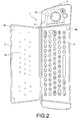
- Figs. 1 and 2 show a top view of a remote control device 1 in accordance with the invention with a cover 2 closed and open, respectively.
- the cover is attached to the device body by means of a hinge 3.
- a first keypad 4 is fixedly attached to the device body and the cover carries a second keypad 5.
- the first keypad 4 is a full alphanumeric QWERTY keypad having a conventional layout. That is, the keys are arranged, and text on and next to the keys is printed, such that when the device is operated, its length axis is perpendicular to the imaginary line from the remote control device to the controlled appliance.
- the second keypad 5 comprises keys for controlling the appliance in a conventional manner, for example, keys for entering a channel number, for incrementing or decrementing the volume or channel number, for controlling the tape function of a VCR, etc.
- the layout of this keypad is such that when the device is operated, its length axis is aimed towards the controlled appliance.
- a trackball or mousepad 10 for controlling a cursor is also provided.
- Fig. 1 further shows two infrared Light Emitting Diodes (LEDs), one infrared LED 7 being located at the top side of the device and emitting infrared light in a direction 7a corresponding to the device's length axis, and one infrared LED 8 being located at the left side and emitting infrared light in a direction 8a corresponding to the device's width axis.
- LEDs Light Emitting Diodes
- a switch 9 is also shown in the Figs.
- the switch 9 comprises a first member 9a which is fixedly attached to the device body and a second member 9b which is fixedly attached to the cover 2. Upon closing the cover, both members 9a and 9b engage each other. The switch 9 is thus closed when the cover is closed.
- the second keypad 5 on the cover 2 may be an autonomous keypad. This is understood to mean that each key includes an individual sensor which, when the key is depressed, applies a corresponding signal to the device's electric circuitry through a flexible wiring arrangement (not shown).
- the cover 2 includes holes 2a, one for each key. Through said holes, a protrusion of each key extends underneath the cover so as to mechanically activate the underlying key of keypad 4 if the cover is closed. For example, the key labeled "5" of keypad 5 activates the key labeled "J" of keypad 4.
- FIG. 3 A schematic diagram of the electric circuitry of the remote control device in accordance with the invention is shown in Fig. 3 .
- the device comprises a microprocessor 30 which is connected to the keypad 4 and the members 9a and 9b of the switch 9 through various input and output port terminals.
- the microprocessor is further connected to a driver stage 37 for driving the top-LED 7 and to a driver stage 38 for driving the side-LED 8.
- the processor is also connected to a read-only-memory (ROM) 31 having a memory section 311 in which a first set of remote control command codes is stored, a memory section 312 in which a second set of remote control command codes is stored, and a memory section 313 in which a control program defining the operation of the processor is stored.
- ROM read-only-memory
- the ROM may also be embedded in the microprocessor.
- a flow chart of operations performed by the microprocessor is shown in Fig. 4 .
- the processor scans the keypad 4 , awaits the depression of a key and identifies which key has been depressed.
- the processor checks whether the switch 9 is closed. If the switch is not closed (i.e., the cover 2 is open), it is concluded that an alphanumeric key of keypad 4 is depressed. In that case the processor reads, in a step 42, the command code to be transmitted from the first memory section 311 of ROM 31. Then, in a step 43, the relevant command code is applied to driver stage 38 which drives the side-LED 8 so as to emit the infrared command signal in the direction of the width-axis 8a.
- the processor reads, in a step 44 , the command code to be transmitted from the second memory section 312 of ROM 31. Then, in a step 45 , the relevant command code is applied to driver stage 37 which drives the top-LED 7 so as to emit the infrared command signal in the direction of the length-axis 7a.
- driver stage 37 drives the top-LED 7 so as to emit the infrared command signal in the direction of the length-axis 7a.
- a remote control device (1) for controlling a "Web-TV".
- the device has a first keypad (5) for controlling the conventional TV and VCR functions.
- the normal TV and VCR control commands are transmitted through a top-LED (7) in a first direction (7a).
- the keypad is accommodated on a cover (2).
- a second keypad is accessible for entering alphanumeric data such as Web-addresses and e-mails.
- the device is rotated through 90 degrees.
- the key commands are transmitted through a side-LED (8) in a second direction (8a).
- a switch (9) detects whether the cover is open or closed and activates the relevant LED.
Landscapes
- Engineering & Computer Science (AREA)
- Multimedia (AREA)
- Human Computer Interaction (AREA)
- Signal Processing (AREA)
- Computer Networks & Wireless Communication (AREA)
- Selective Calling Equipment (AREA)
- Input From Keyboards Or The Like (AREA)
Abstract
Claims (3)
- Dispositif portable de commande à distance (1) comprenant un premier clavier numérique pour générer des premiers signaux de commande et une couverture (2) qui est fixée de façon pivotante au dispositif et qui couvre le premier clavier numérique (4) lorsqu'il est fermé, ladite couverture portant un deuxième clavier numérique (5) pour générer des deuxièmes signaux de commande, caractérisé en ce que le dispositif présente une forme allongée ayant un axe de longueur et un axe de largeur, le premier clavier numérique (4) étant présenté pour utiliser le dispositif dans une première direction correspondant audit axe de longueur ou audit axe de largeur et le deuxième clavier numérique (5) étant présenté pour utiliser un dispositif dans une deuxième direction qui est perpendiculaire à ladite première direction, en ce que le dispositif comprend des moyens émetteurs (7, 8) pour émettre les signaux de commande sous forme de faisceaux directionnels, lesdits moyens émetteurs comprenant des premiers moyens émetteurs (8) pour émettre les premiers signaux de commande dans sensiblement la première direction et des deuxièmes moyens émetteurs (7) pour émettre les deuxièmes signaux de commande dans sensiblement la deuxième direction, et en ce qu'il comprend encore des moyens de détection (9a, b) pour détecter si la couverture est ouverte ou fermée, les moyens de détection étant agencés de manière à désactiver les deuxièmes moyens émetteurs (8) si la couverture est ouverte et à désactiver les premiers moyens émetteurs (7) si la couverture est fermée.
- Dispositif selon la revendication 1, dans lequel des touches du deuxième clavier numérique (5) dépassent au-dessous de la couverture (2) de manière à activer mécaniquement les touches correspondantes du premier clavier numérique (4) lorsque la couverture est fermée, le dispositif comprenant encore des moyens de détection (9a, b) pour détecter si la couverture est ouverte ou fermée, les moyens de détection étant agencés de manière à activer les premiers signaux de commande à générer si la couverture est ouverte et à activer les deuxièmes signaux de commande à générer si la couverture est fermée.
- Dispositif selon l'une quelconque des revendications précédentes 1 à 2, dans lequel le deuxième clavier comprend des touches pour commander des fonctions respectives dans un appareil électronique et dans lequel le premier clavier numérique (4) est un clavier alphanumérique pour appliquer des données alphanumériques audit appareil.
Priority Applications (1)
| Application Number | Priority Date | Filing Date | Title |
|---|---|---|---|
| EP99917035A EP1000522B1 (fr) | 1998-05-26 | 1999-05-14 | Appareil de telecommande |
Applications Claiming Priority (4)
| Application Number | Priority Date | Filing Date | Title |
|---|---|---|---|
| EP98201744 | 1998-05-26 | ||
| EP98201744 | 1998-05-26 | ||
| EP99917035A EP1000522B1 (fr) | 1998-05-26 | 1999-05-14 | Appareil de telecommande |
| PCT/IB1999/000883 WO1999062287A2 (fr) | 1998-05-26 | 1999-05-14 | Appareil de telecommande |
Publications (2)
| Publication Number | Publication Date |
|---|---|
| EP1000522A2 EP1000522A2 (fr) | 2000-05-17 |
| EP1000522B1 true EP1000522B1 (fr) | 2008-12-03 |
Family
ID=8233764
Family Applications (1)
| Application Number | Title | Priority Date | Filing Date |
|---|---|---|---|
| EP99917035A Expired - Lifetime EP1000522B1 (fr) | 1998-05-26 | 1999-05-14 | Appareil de telecommande |
Country Status (5)
| Country | Link |
|---|---|
| EP (1) | EP1000522B1 (fr) |
| KR (1) | KR100622289B1 (fr) |
| DE (1) | DE69940008D1 (fr) |
| TW (1) | TW386323B (fr) |
| WO (1) | WO1999062287A2 (fr) |
Cited By (28)
| Publication number | Priority date | Publication date | Assignee | Title |
|---|---|---|---|---|
| US8299695B2 (en) | 2009-06-02 | 2012-10-30 | Ilumisys, Inc. | Screw-in LED bulb comprising a base having outwardly projecting nodes |
| US8330381B2 (en) | 2009-05-14 | 2012-12-11 | Ilumisys, Inc. | Electronic circuit for DC conversion of fluorescent lighting ballast |
| US8362710B2 (en) | 2009-01-21 | 2013-01-29 | Ilumisys, Inc. | Direct AC-to-DC converter for passive component minimization and universal operation of LED arrays |
| US8421366B2 (en) | 2009-06-23 | 2013-04-16 | Ilumisys, Inc. | Illumination device including LEDs and a switching power control system |
| US8454193B2 (en) | 2010-07-08 | 2013-06-04 | Ilumisys, Inc. | Independent modules for LED fluorescent light tube replacement |
| US8523394B2 (en) | 2010-10-29 | 2013-09-03 | Ilumisys, Inc. | Mechanisms for reducing risk of shock during installation of light tube |
| US8540401B2 (en) | 2010-03-26 | 2013-09-24 | Ilumisys, Inc. | LED bulb with internal heat dissipating structures |
| US8541958B2 (en) | 2010-03-26 | 2013-09-24 | Ilumisys, Inc. | LED light with thermoelectric generator |
| US8556452B2 (en) | 2009-01-15 | 2013-10-15 | Ilumisys, Inc. | LED lens |
| US8596813B2 (en) | 2010-07-12 | 2013-12-03 | Ilumisys, Inc. | Circuit board mount for LED light tube |
| US8664880B2 (en) | 2009-01-21 | 2014-03-04 | Ilumisys, Inc. | Ballast/line detection circuit for fluorescent replacement lamps |
| US8807785B2 (en) | 2008-05-23 | 2014-08-19 | Ilumisys, Inc. | Electric shock resistant L.E.D. based light |
| US8870415B2 (en) | 2010-12-09 | 2014-10-28 | Ilumisys, Inc. | LED fluorescent tube replacement light with reduced shock hazard |
| US8928025B2 (en) | 2007-12-20 | 2015-01-06 | Ilumisys, Inc. | LED lighting apparatus with swivel connection |
| US9057493B2 (en) | 2010-03-26 | 2015-06-16 | Ilumisys, Inc. | LED light tube with dual sided light distribution |
| US9072171B2 (en) | 2011-08-24 | 2015-06-30 | Ilumisys, Inc. | Circuit board mount for LED light |
| US9101026B2 (en) | 2008-10-24 | 2015-08-04 | Ilumisys, Inc. | Integration of LED lighting with building controls |
| US9163794B2 (en) | 2012-07-06 | 2015-10-20 | Ilumisys, Inc. | Power supply assembly for LED-based light tube |
| US9184518B2 (en) | 2012-03-02 | 2015-11-10 | Ilumisys, Inc. | Electrical connector header for an LED-based light |
| US9271367B2 (en) | 2012-07-09 | 2016-02-23 | Ilumisys, Inc. | System and method for controlling operation of an LED-based light |
| US9267650B2 (en) | 2013-10-09 | 2016-02-23 | Ilumisys, Inc. | Lens for an LED-based light |
| US9285084B2 (en) | 2013-03-14 | 2016-03-15 | Ilumisys, Inc. | Diffusers for LED-based lights |
| US9353939B2 (en) | 2008-10-24 | 2016-05-31 | iLumisys, Inc | Lighting including integral communication apparatus |
| US9398661B2 (en) | 2008-10-24 | 2016-07-19 | Ilumisys, Inc. | Light and light sensor |
| US9510400B2 (en) | 2014-05-13 | 2016-11-29 | Ilumisys, Inc. | User input systems for an LED-based light |
| US9574717B2 (en) | 2014-01-22 | 2017-02-21 | Ilumisys, Inc. | LED-based light with addressed LEDs |
| US10161568B2 (en) | 2015-06-01 | 2018-12-25 | Ilumisys, Inc. | LED-based light with canted outer walls |
| US10176689B2 (en) | 2008-10-24 | 2019-01-08 | Ilumisys, Inc. | Integration of led lighting control with emergency notification systems |
Families Citing this family (13)
| Publication number | Priority date | Publication date | Assignee | Title |
|---|---|---|---|---|
| RU2167490C1 (ru) * | 2000-01-10 | 2001-05-20 | Раков Дмитрий Леонидович | Пульт дистанционного управления |
| RU2283535C2 (ru) * | 2003-07-17 | 2006-09-10 | Государственное образовательное учреждение высшего профессионального образования "Южно-Российский государственный технический университет (Новочеркассикй политехнический институт)" ГОУ ВПО ЮРГТУ (НПИ) | Пульт дистанционного управления |
| WO2005073939A1 (fr) * | 2004-01-28 | 2005-08-11 | Clifford David Wilkinson | Unite de telecommande |
| KR101069765B1 (ko) * | 2004-06-03 | 2011-10-04 | 엘지전자 주식회사 | 폴더형 리모컨 |
| EP2007166B1 (fr) * | 2006-04-13 | 2014-05-07 | Toto Ltd. | Contrôleur distant |
| JP4807262B2 (ja) * | 2007-01-09 | 2011-11-02 | 船井電機株式会社 | リモコン装置 |
| FR2917515B1 (fr) | 2007-06-13 | 2010-05-14 | Archos Sa | Dispositif de telecommande sans fil pour lecteur- enregistreur numerique multimedia connectable a un reseau et systeme associe. |
| EP2487663B1 (fr) | 2011-02-11 | 2014-12-31 | Fm Marketing GmbH | Télécommande |
| US9734707B2 (en) * | 2012-01-09 | 2017-08-15 | Universal Electronics Inc. | Features for use with a multi-sided controlling device |
| TWM440603U (en) * | 2012-05-30 | 2012-11-01 | Hon Hai Prec Ind Co Ltd | Remote control device |
| KR101339035B1 (ko) * | 2013-09-12 | 2013-12-09 | 리모트솔루션주식회사 | 폴더형 리모컨 |
| JP6573815B2 (ja) * | 2015-10-19 | 2019-09-11 | 株式会社Lixil | リモコン装置 |
| KR102794103B1 (ko) * | 2022-09-16 | 2025-04-14 | 주식회사 오성전자 | 전자제품용 통합 리모컨 |
Family Cites Families (7)
| Publication number | Priority date | Publication date | Assignee | Title |
|---|---|---|---|---|
| JPS63117243U (fr) * | 1987-01-26 | 1988-07-28 | ||
| DE3713428A1 (de) * | 1987-04-22 | 1988-11-03 | Unterhaltungselectronic Ohg De | Fernbedieneinheit fuer elektrische geraete |
| US5181024A (en) * | 1988-11-30 | 1993-01-19 | Kabushiki Kaisha Toshiba | Book type wireless remote control apparatus |
| US5534865A (en) * | 1992-11-20 | 1996-07-09 | Kriegsman; Irving M. | Ergonomic wireless remote control transmitter for use with consumer entertainment electronics appliance |
| DE19520947C5 (de) * | 1995-06-02 | 2012-04-05 | Constin Design Gmbh | Tragbarer Computer mit Telekommunikationseinrichtung |
| JP3172399B2 (ja) * | 1995-08-01 | 2001-06-04 | 三洋電機株式会社 | リモートコントロール装置 |
| JPH1032887A (ja) * | 1996-07-15 | 1998-02-03 | Sanyo Electric Co Ltd | 2方向リモコン送信器 |
-
1998
- 1998-11-04 TW TW087118309A patent/TW386323B/zh not_active IP Right Cessation
-
1999
- 1999-05-14 DE DE69940008T patent/DE69940008D1/de not_active Expired - Fee Related
- 1999-05-14 EP EP99917035A patent/EP1000522B1/fr not_active Expired - Lifetime
- 1999-05-14 KR KR1020007000749A patent/KR100622289B1/ko not_active Expired - Fee Related
- 1999-05-14 WO PCT/IB1999/000883 patent/WO1999062287A2/fr not_active Ceased
Cited By (39)
| Publication number | Priority date | Publication date | Assignee | Title |
|---|---|---|---|---|
| US8928025B2 (en) | 2007-12-20 | 2015-01-06 | Ilumisys, Inc. | LED lighting apparatus with swivel connection |
| US8807785B2 (en) | 2008-05-23 | 2014-08-19 | Ilumisys, Inc. | Electric shock resistant L.E.D. based light |
| US9635727B2 (en) | 2008-10-24 | 2017-04-25 | Ilumisys, Inc. | Light and light sensor |
| US10036549B2 (en) | 2008-10-24 | 2018-07-31 | Ilumisys, Inc. | Lighting including integral communication apparatus |
| US9398661B2 (en) | 2008-10-24 | 2016-07-19 | Ilumisys, Inc. | Light and light sensor |
| US10342086B2 (en) | 2008-10-24 | 2019-07-02 | Ilumisys, Inc. | Integration of LED lighting with building controls |
| US9353939B2 (en) | 2008-10-24 | 2016-05-31 | iLumisys, Inc | Lighting including integral communication apparatus |
| US9585216B2 (en) | 2008-10-24 | 2017-02-28 | Ilumisys, Inc. | Integration of LED lighting with building controls |
| US9101026B2 (en) | 2008-10-24 | 2015-08-04 | Ilumisys, Inc. | Integration of LED lighting with building controls |
| US10176689B2 (en) | 2008-10-24 | 2019-01-08 | Ilumisys, Inc. | Integration of led lighting control with emergency notification systems |
| US10182480B2 (en) | 2008-10-24 | 2019-01-15 | Ilumisys, Inc. | Light and light sensor |
| US8556452B2 (en) | 2009-01-15 | 2013-10-15 | Ilumisys, Inc. | LED lens |
| US8362710B2 (en) | 2009-01-21 | 2013-01-29 | Ilumisys, Inc. | Direct AC-to-DC converter for passive component minimization and universal operation of LED arrays |
| US8664880B2 (en) | 2009-01-21 | 2014-03-04 | Ilumisys, Inc. | Ballast/line detection circuit for fluorescent replacement lamps |
| US8330381B2 (en) | 2009-05-14 | 2012-12-11 | Ilumisys, Inc. | Electronic circuit for DC conversion of fluorescent lighting ballast |
| US8299695B2 (en) | 2009-06-02 | 2012-10-30 | Ilumisys, Inc. | Screw-in LED bulb comprising a base having outwardly projecting nodes |
| US8421366B2 (en) | 2009-06-23 | 2013-04-16 | Ilumisys, Inc. | Illumination device including LEDs and a switching power control system |
| US8540401B2 (en) | 2010-03-26 | 2013-09-24 | Ilumisys, Inc. | LED bulb with internal heat dissipating structures |
| US9057493B2 (en) | 2010-03-26 | 2015-06-16 | Ilumisys, Inc. | LED light tube with dual sided light distribution |
| US9013119B2 (en) | 2010-03-26 | 2015-04-21 | Ilumisys, Inc. | LED light with thermoelectric generator |
| US8840282B2 (en) | 2010-03-26 | 2014-09-23 | Ilumisys, Inc. | LED bulb with internal heat dissipating structures |
| US8541958B2 (en) | 2010-03-26 | 2013-09-24 | Ilumisys, Inc. | LED light with thermoelectric generator |
| US9395075B2 (en) | 2010-03-26 | 2016-07-19 | Ilumisys, Inc. | LED bulb for incandescent bulb replacement with internal heat dissipating structures |
| US8454193B2 (en) | 2010-07-08 | 2013-06-04 | Ilumisys, Inc. | Independent modules for LED fluorescent light tube replacement |
| US8596813B2 (en) | 2010-07-12 | 2013-12-03 | Ilumisys, Inc. | Circuit board mount for LED light tube |
| US8523394B2 (en) | 2010-10-29 | 2013-09-03 | Ilumisys, Inc. | Mechanisms for reducing risk of shock during installation of light tube |
| US8894430B2 (en) | 2010-10-29 | 2014-11-25 | Ilumisys, Inc. | Mechanisms for reducing risk of shock during installation of light tube |
| US8870415B2 (en) | 2010-12-09 | 2014-10-28 | Ilumisys, Inc. | LED fluorescent tube replacement light with reduced shock hazard |
| US9072171B2 (en) | 2011-08-24 | 2015-06-30 | Ilumisys, Inc. | Circuit board mount for LED light |
| US9184518B2 (en) | 2012-03-02 | 2015-11-10 | Ilumisys, Inc. | Electrical connector header for an LED-based light |
| US9163794B2 (en) | 2012-07-06 | 2015-10-20 | Ilumisys, Inc. | Power supply assembly for LED-based light tube |
| US9271367B2 (en) | 2012-07-09 | 2016-02-23 | Ilumisys, Inc. | System and method for controlling operation of an LED-based light |
| US9807842B2 (en) | 2012-07-09 | 2017-10-31 | Ilumisys, Inc. | System and method for controlling operation of an LED-based light |
| US9285084B2 (en) | 2013-03-14 | 2016-03-15 | Ilumisys, Inc. | Diffusers for LED-based lights |
| US9267650B2 (en) | 2013-10-09 | 2016-02-23 | Ilumisys, Inc. | Lens for an LED-based light |
| US10260686B2 (en) | 2014-01-22 | 2019-04-16 | Ilumisys, Inc. | LED-based light with addressed LEDs |
| US9574717B2 (en) | 2014-01-22 | 2017-02-21 | Ilumisys, Inc. | LED-based light with addressed LEDs |
| US9510400B2 (en) | 2014-05-13 | 2016-11-29 | Ilumisys, Inc. | User input systems for an LED-based light |
| US10161568B2 (en) | 2015-06-01 | 2018-12-25 | Ilumisys, Inc. | LED-based light with canted outer walls |
Also Published As
| Publication number | Publication date |
|---|---|
| EP1000522A2 (fr) | 2000-05-17 |
| WO1999062287A3 (fr) | 2000-01-13 |
| WO1999062287A2 (fr) | 1999-12-02 |
| KR100622289B1 (ko) | 2006-09-11 |
| TW386323B (en) | 2000-04-01 |
| DE69940008D1 (de) | 2009-01-15 |
| KR20010022177A (ko) | 2001-03-15 |
Similar Documents
| Publication | Publication Date | Title |
|---|---|---|
| EP1000522A2 (fr) | Appareil de telecommande | |
| US5785439A (en) | Environmentally safe machine control security switch | |
| KR100477126B1 (ko) | 광다이얼기능을가진컴퓨터 | |
| US5986586A (en) | Keyboard with additional hot keys | |
| EP1209661B1 (fr) | Télécommande universelle adaptée à recevoir des commandes vocales | |
| US20070247338A1 (en) | Remote control device | |
| JPS61111074A (ja) | テレビジヨン受像機 | |
| US5973622A (en) | Keyboard with a two-dimensional actuator for generating direction signals | |
| MXPA00000795A (en) | Remote control device | |
| KR100237242B1 (ko) | 커서제어 스위치 시스템의 커서제어 방법 | |
| KR100205816B1 (ko) | 키패드 입력수단을 갖는 리모콘 송/수신 시스템과 패드입력 처리방법 | |
| KR100774513B1 (ko) | 다기능 트랙볼 마우스 | |
| KR0170142B1 (ko) | 초간편 원격조정기 | |
| KR200286424Y1 (ko) | 휴대용 키보드 | |
| KR0135471Y1 (ko) | 리모콘 시스템의 오동작 방지 장치 | |
| KR100259705B1 (ko) | 리모컨 사용자의 키 누름 패턴 검출 방법 및 이를 이용한 패스워드 설정/해독 방법 | |
| JP3526759B2 (ja) | パーソナルコンピュータ用キーボード | |
| KR200327335Y1 (ko) | 전자기기용 신호 입력장치 | |
| KR19990047538A (ko) | 브이시알 리모콘의 송신코드 제어방법 | |
| KR200404474Y1 (ko) | 다기능 트랙볼 마우스 | |
| KR970003091Y1 (ko) | 밧데리 케이스 구조 | |
| KR200148875Y1 (ko) | 기능키작동 감지장치 | |
| KR200167621Y1 (ko) | 자판 작동 제어 키보드 | |
| KR19980038658U (ko) | Cd롬(cd-rom) 도어의 개폐장치 | |
| WO1994014241A1 (fr) | Dispositif de telecommande dote d'un mode de reaffectation des fonctions de touche |
Legal Events
| Date | Code | Title | Description |
|---|---|---|---|
| PUAI | Public reference made under article 153(3) epc to a published international application that has entered the european phase |
Free format text: ORIGINAL CODE: 0009012 |
|
| 17P | Request for examination filed |
Effective date: 20000228 |
|
| AK | Designated contracting states |
Kind code of ref document: A2 Designated state(s): BE DE FR GB |
|
| 17Q | First examination report despatched |
Effective date: 20060818 |
|
| GRAP | Despatch of communication of intention to grant a patent |
Free format text: ORIGINAL CODE: EPIDOSNIGR1 |
|
| GRAS | Grant fee paid |
Free format text: ORIGINAL CODE: EPIDOSNIGR3 |
|
| GRAS | Grant fee paid |
Free format text: ORIGINAL CODE: EPIDOSNIGR3 |
|
| GRAA | (expected) grant |
Free format text: ORIGINAL CODE: 0009210 |
|
| AK | Designated contracting states |
Kind code of ref document: B1 Designated state(s): BE DE FR GB |
|
| REG | Reference to a national code |
Ref country code: GB Ref legal event code: FG4D |
|
| REF | Corresponds to: |
Ref document number: 69940008 Country of ref document: DE Date of ref document: 20090115 Kind code of ref document: P |
|
| PG25 | Lapsed in a contracting state [announced via postgrant information from national office to epo] |
Ref country code: BE Free format text: LAPSE BECAUSE OF FAILURE TO SUBMIT A TRANSLATION OF THE DESCRIPTION OR TO PAY THE FEE WITHIN THE PRESCRIBED TIME-LIMIT Effective date: 20081203 |
|
| PLBE | No opposition filed within time limit |
Free format text: ORIGINAL CODE: 0009261 |
|
| STAA | Information on the status of an ep patent application or granted ep patent |
Free format text: STATUS: NO OPPOSITION FILED WITHIN TIME LIMIT |
|
| 26N | No opposition filed |
Effective date: 20090904 |
|
| GBPC | Gb: european patent ceased through non-payment of renewal fee |
Effective date: 20090514 |
|
| REG | Reference to a national code |
Ref country code: FR Ref legal event code: ST Effective date: 20100129 |
|
| PG25 | Lapsed in a contracting state [announced via postgrant information from national office to epo] |
Ref country code: FR Free format text: LAPSE BECAUSE OF NON-PAYMENT OF DUE FEES Effective date: 20090602 |
|
| PG25 | Lapsed in a contracting state [announced via postgrant information from national office to epo] |
Ref country code: GB Free format text: LAPSE BECAUSE OF NON-PAYMENT OF DUE FEES Effective date: 20090514 |
|
| PG25 | Lapsed in a contracting state [announced via postgrant information from national office to epo] |
Ref country code: DE Free format text: LAPSE BECAUSE OF NON-PAYMENT OF DUE FEES Effective date: 20091201 |