EP1000532B1 - Transportables Kleinrührwerk - Google Patents
Transportables Kleinrührwerk Download PDFInfo
- Publication number
- EP1000532B1 EP1000532B1 EP99122207A EP99122207A EP1000532B1 EP 1000532 B1 EP1000532 B1 EP 1000532B1 EP 99122207 A EP99122207 A EP 99122207A EP 99122207 A EP99122207 A EP 99122207A EP 1000532 B1 EP1000532 B1 EP 1000532B1
- Authority
- EP
- European Patent Office
- Prior art keywords
- portable small
- agitator
- small agitator
- locking
- drive shaft
- Prior art date
- Legal status (The legal status is an assumption and is not a legal conclusion. Google has not performed a legal analysis and makes no representation as to the accuracy of the status listed.)
- Expired - Lifetime
Links
- 230000000903 blocking effect Effects 0.000 claims description 9
- 239000007787 solid Substances 0.000 claims description 8
- 238000011010 flushing procedure Methods 0.000 claims description 7
- 239000002002 slurry Substances 0.000 claims description 3
- 239000012530 fluid Substances 0.000 claims 1
- 239000002184 metal Substances 0.000 claims 1
- 230000002093 peripheral effect Effects 0.000 claims 1
- 239000007788 liquid Substances 0.000 description 13
- 238000003756 stirring Methods 0.000 description 11
- 239000003599 detergent Substances 0.000 description 7
- 210000003608 fece Anatomy 0.000 description 5
- 239000010871 livestock manure Substances 0.000 description 5
- 239000003795 chemical substances by application Substances 0.000 description 3
- 210000003746 feather Anatomy 0.000 description 2
- 239000004615 ingredient Substances 0.000 description 2
- 230000001681 protective effect Effects 0.000 description 2
- 241001465754 Metazoa Species 0.000 description 1
- 230000006978 adaptation Effects 0.000 description 1
- 230000000295 complement effect Effects 0.000 description 1
- 230000003750 conditioning effect Effects 0.000 description 1
- 238000001816 cooling Methods 0.000 description 1
- 230000008878 coupling Effects 0.000 description 1
- 238000010168 coupling process Methods 0.000 description 1
- 238000005859 coupling reaction Methods 0.000 description 1
- 230000006378 damage Effects 0.000 description 1
- 230000001419 dependent effect Effects 0.000 description 1
- 238000004851 dishwashing Methods 0.000 description 1
- 238000006073 displacement reaction Methods 0.000 description 1
- 239000012535 impurity Substances 0.000 description 1
- 230000010354 integration Effects 0.000 description 1
- 238000002955 isolation Methods 0.000 description 1
- 238000011089 mechanical engineering Methods 0.000 description 1
- 238000005086 pumping Methods 0.000 description 1
- 230000000284 resting effect Effects 0.000 description 1
- 238000005096 rolling process Methods 0.000 description 1
- 230000000087 stabilizing effect Effects 0.000 description 1
- 230000003319 supportive effect Effects 0.000 description 1
- 239000008399 tap water Substances 0.000 description 1
- 235000020679 tap water Nutrition 0.000 description 1
- XLYOFNOQVPJJNP-UHFFFAOYSA-N water Substances O XLYOFNOQVPJJNP-UHFFFAOYSA-N 0.000 description 1
Images





Classifications
-
- A—HUMAN NECESSITIES
- A01—AGRICULTURE; FORESTRY; ANIMAL HUSBANDRY; HUNTING; TRAPPING; FISHING
- A01C—PLANTING; SOWING; FERTILISING
- A01C3/00—Treating manure; Manuring
- A01C3/02—Storage places for manure, e.g. cisterns for liquid manure; Installations for fermenting manure
- A01C3/026—Storage places for manure, e.g. cisterns for liquid manure; Installations for fermenting manure with mixing or agitating devices
Definitions
- the invention relates to a portable small agitator according to the preamble of claim 1.
- Such small agitators are preferably used for crushing and distributing solid components, such as those contained in manure and other liquids.
- the field of application thus mainly includes stables for the keeping of animals or small pits for private households.
- a portable small agitator for crushing solid components in manure and other liquids with a chassis with at least two wheels is known in which a drive unit is arranged on a support member having a connection to a drive shaft. At the end, the drive shaft has agitator blades.
- the drive unit is mounted pivotably about an axis on the support member and arranged by means of a locking device in a plurality of pivot positions fixable on the support member.
- Such a portable small agitator has a chassis with four wheels.
- a drive unit On a support member, a drive unit is arranged, which has a drive shaft with impellers and is slidably disposed within the chassis together with the support member in height.
- the drive unit is pivotable about an approximately horizontal axis, this axis is part of a guide and not on the support member, but arranged on this and in the guides of the chassis. It is moved in the height adjustment together with the drive unit and the drive shaft.
- a portable small agitator which in addition to a chassis on two wheels also has a support member on which a drive unit is arranged.
- a drive unit in this case an electric motor was used.
- the drive unit also has a drive shaft, at the end of a stirring blade is attached.
- the rotor blades are pivoted during operation due to the centrifugal force about its mounting axis so that the stirring blades develop after commissioning of the small agitator to a rotor.
- two U-shaped posts are known from the document, between which spars of the frame structure are longitudinally displaceable, that is variable in height, out.
- the stationary, vertically arranged stirring blades are pushed through the column gratings in the slurry channel, where they unfold after switching on the device in the manner described above, thus enabling the crushing of the solid components in the manure.
- a disadvantage of this solution is that the stirring blades can only be used in one direction. It is therefore not possible to a directional flow produce, within the channel at the same time facilitates the removal of the crushed ingredients together with the liquid.
- the disadvantage that the wheels are unsecured, so that there is a risk that the device unintentionally moves independently, tilts or slips, which can ultimately lead to destruction of the impeller by jamming in the channel or between the columns and thus also a risk of accidents.
- the invention is based on the technical problem to provide a portable small agitator that allows crushing solid ingredients in liquids and thereby generates a directed flow within the liquid, which is safe and should be inexpensive to produce. Furthermore, the small agitator in unused condition should be reducible to minimum dimensions.
- the drive unit is pivotally mounted about an axis on the support member and slidably with this in the chassis.
- the drive unit is further arranged by means of a locking device in a plurality of pivot positions fixable on the support member and the pivot angle of the locking device can be between 0 ° and 360 °.
- This design has the advantage that not only a vertical displacement of the entire drive unit is possible, it is also achieved that this can be arbitrarily pivoted on the support member and fixed in any position, which greatly facilitates the portability of the device.
- the additional integration of the pivoting function for example, a directed flow can be generated in a slurry channel, which promotes the discharge of the liquid and facilitated.
- a directed flow can be generated in a slurry channel, which promotes the discharge of the liquid and facilitated.
- Embodiments of the invention are the subject of the dependent claims.
- the chassis can be performed in one embodiment of the invention as a self-contained frame profile.
- Two mutually parallel frame profiles are each designed as guides in which the support member is displaced in height.
- the guides may be according to the invention, for example, U-profiles, dovetail guides, slot guides or T-profiles. Other known designs are, of course, applicable.
- T-profiles the support member surrounds the guide claw-like, while using U-profiles, dovetail guides or slot guides, the support member is used frame profile side in the guide.
- At least two support members are provided, which are arranged on the opposite side of the wheels.
- These support beams form, for example, an equilateral triangle, which means that their ends advantageously form an obtuse angle, with the vertex located on the chassis.
- the arranged on the support member drive unit according to the invention fixed by means of a locking device in a plurality of pivot positions fixable on the support member. This determination in several pivot positions prevents otherwise required expectant holding in a defined position.
- the ease of operation of the small agitator over known devices has been significantly improved.
- a further embodiment of the invention also provides that the locking device consists of a rotatably mounted on the support plate, in whose edge region is formed a curve contour with the pivot positions associated recesses into which a locking member engages.
- the locking member can also be completely overridden, so that a permanent swinging back and forth of the drive unit by the operator is possible.
- the locking member may be a spring-ball detent, a clamping lever or a threaded bolt which can be screwed in an inserted or attached near the edge of the plate edge.
- the pivot angle of the drive unit is according to the invention up to 360 °.
- the drive unit for transport facilitating could be pivoted, for example, by 180 °, in order to then spend it with the support member in the lowest, Radnahe position.
- an advantageous weight distribution is achieved and the entire small agitator very compact.
- the support bars should be telescopic.
- the telescoping can be done in a conventional manner by telescoping, complementary profiles. These can be connected to one another via a captive or be supplemented for example by connectors to the necessary length.
- the portable small agitator has at least one, but preferably two handles, which also may also be telescoped. Furthermore, it is of particular advantage, the handles height adjustable and pivotable about an axis as well as perform in several positions in the frame profile fixable. As a result, on the one hand an adaptation to different body sizes of the operator and on the other hand a simplified transportability of the small agitator is made possible.
- the pivotability of the handles according to the invention for example, achieved in that they are each pivotally received in a sleeve, which may consist of two parallel sheets.
- This sleeve has the height adjustment or the pivot positions corresponding holes.
- the axis about which the handles are pivoted in the simplest case may consist of a bolt which passes through the holes in the cuff and the handle and has a captive end.
- captive known devices can be used in mechanical engineering, such as nuts with cotter pins, self-locking nuts, ratchet nuts and others.
- Another very significant embodiment of the invention provides a coupling of the handles with a force acting on the wheels, releasable blocking device.
- This blocking device is to be understood as a lever mechanism, for example, which consists of a coupled with the handles push rod and a wheel side attached to the push rod and acting on the wheels brake rod. Between the brake rod and the chassis acts a tension spring, so that the brake rod acts permanently on the wheels, that is, is pressed against them.
- the brake rod is slidably guided in a brake rod guide. To move the small agitator, the operator must grasp it by the handles and pull it towards you so that it is brought into an inclined position. The blocking of the wheels by the resting brake rod is supportive.
- the brake rod guide can in the simplest case consist of a slot in which the brake rod is slidably guided. It is essential, however, that the brake rod is pulled in the released state against a stop. This will simultaneously limit the Pivoting movement of the handles reached.
- the stop can be the upper end of the aforementioned slot.
- a lifting device attached to the chassis, which supports the movement of the support member.
- a lifting device can be used according to the invention a winch or a supported by the force of a spring, by a hydraulic or by a pneumatic lifting mechanism.
- a portable small agitator may store the drive shaft floating, so as to allow, for example, a cooling of the bearing in the vicinity Retzerielnahen and beyond foreign bodies, such as impurities, rinse out of the bearing.
- the floating bearing which may consist of a bearing housing with a detergent connection and a detergent channel, a further reduction in friction is achieved, so that the wear of the small agitator is reduced.
- the flushing agent channel could have at least one outlet opening connected to the bearing bore receiving the drive shaft and at least one further, free outlet opening directed in the direction of the stirring wing.
- the stirring blade consists of at least one rigidly connected to the drive shaft agitator blade and on the drive shaft, a device for locking the agitator is present in at least one position, wherein the device for locking the agitator of a with the Drive shaft coupled cam member and a cooperating with this locking lever.
- the cam element should advantageously be secured by means of a Reduzierhülse on the drive shaft and arranged in a plane with the impeller and have an approximately elliptical shape.
- the total rotatable and axially movable locking lever according to this embodiment of the invention consists of a handle, a penetrated by the locking lever disc, on the one hand against the disc and on the other hand inside a sleeve supporting spring, wherein the sleeve is fixed by means of a lock nut on the locking lever , On the locking lever, an additional lever arm can be provided, which defines at least one support surface at least two positions of the locking lever. During the adjustment of the Arretierhebls the disc slides along a curved path.
- the embodiment of the invention shown in Figures 1 to 3 is a very simple, portable small agitator for crushing solid components in manure and other liquids.
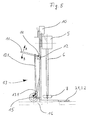
- This consists of a chassis (1) with at least two wheels (2), a support member (4), arranged on the support member drive unit (5) with a drive shaft (6), the end at least one stirring blade (7), wherein the Drive unit (5) about an axis (8) pivotally on the support member (4) and with the support member (4) slidably received in the chassis (1).
- the impeller (7) is designed like a propeller and can unfold in a conventional manner when it is placed in a rotary motion.
- the approximately 1 m long drive shaft can in turn be accommodated in a protective tube, not shown in the figures, wherein an outwardly sealed rolling bearing at the end of the protective tube ensures adequate guidance of the drive shaft.
- the drive unit used is an electric motor with a capacity of approximately 6 kW.
- On the chassis (1) two handles (11) are also mounted.
- the chassis (1) is self-contained and has two mutually parallel frame profiles (1.1, 1.2), each guide (1.1.1, 1.2.1) for the movable therein support member (4).
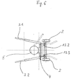
- the guides U-profiles In the illustrated embodiment of a solution according to the invention are the guides U-profiles. This can be clearly seen in the representation of FIG.
- the sleeve (14) is a simple sheet, which has a plurality of holes offset in height and by a the axis (12) forming bolt is penetrated.
- a height adjustment and pivoting of the handles (11) can be achieved in a particularly simple manner.
- Two arranged on the opposite side of the wheels supporting spars (3.1, 3.2) are telescopic, so that a total of a fixed state of the entire small agitator is achieved.
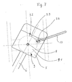
- the drive unit (5) arranged on the support part (4) is further fixed in a plurality of pivoting positions on the support part (4) by means of a locking device (9), as can be seen in particular from the illustration in FIG.
- This locking device (9) consists of a on the support member (4) rotatably mounted plate (9.1), in the edge region of a curve contour (9.2) with the pivot positions associated recesses (9.3) is formed, into which a locking member (9.4) engages.
- a locking member present at the end of the adjusting lever (17) attached threaded bolt is used, which is screwed by a nut welded to the drive unit until its end engages in the corresponding recess (9.3) and so determines the locking device (9) in position.
- the adjusting handle (17) on the drive unit (5) facilitates the pivoting movement of the drive unit (5) about the axis (8).
- the small agitator according to the invention is first placed on the slatted frame (16) of the stable. Subsequently, the drive unit (5) is moved together with the support member (4) down so that the impeller (7) below the slatted frame (16) dips into the thickened liquid.
- the drive unit can be started, and it is now possible simultaneously pivoting about the axis (8) or a determination of the drive unit in any pivot position. Depending on the impeller design, it may be necessary to remove a slatted frame to be able to insert the impeller.
- the support bars act here in particular by their telescopability stability-promoting for the entire device.
- the handles (11) are telescopic, height adjustable and pivotable about an axis (12). Furthermore, they can be defined in several positions.
- the handles (11) in each case in a sleeve (14) are pivotally received, which may have the height adjustment or the pivot positions corresponding holes, wherein the axis (12) consists of a bolt, the holes in the sleeve (14) and the Handle (11) passes through and ends contain a captive.
- the sleeve (14) as shown in Figure 5, two superimposed holes are introduced, so that the handles can be mounted in two different positions.
- a determination of the handles (11) in different pivot positions is not provided in the illustrated embodiment in Figure 5.
- the handles (11) are further coupled to a releasable blocking device (13) acting on the wheels (2).
- This blocking device (13) is a lever mechanism which has a push rod (13.1) coupled to the handles (11), a brake rod (13.2) attached to the push rod and acting on the wheels (2), at least one on the brake rod (13.2 ) and on the other hand on the chassis (1) fixed tension spring (13.3) and a brake rod guide (13.4).
- the push rod is made adjustable in several positions in height. As can be seen in the illustration of Figure 5, this is achieved by a plurality of bores, which are introduced into the push rod, to the handles (11) a bolt connection is created. Another possible height adjustment of the push rod is schematically greatly simplified and shown without attachments in Figure 9.
- a sheet is attached to the handles, which has a plurality of holes through which a bolt ensures a height-adjustable connection with the push rod.
- the brake rod guide (13.4) includes a slot (15) in which the brake rod (13.2) is slidably guided.
- lifting device (10) supports the adjustment movement of the support member (4).
- a lifting device (10) in each case a winch is used in the embodiments shown in the figures.
- FIG. 10 shows a floating mounting of the drive shaft (6).
- This consists of a bearing housing (18) with a detergent connection (19) and a detergent channel (20).
- tap water can be used as flushing agent, which is led from the water network via the flushing agent connection (19) directly into the storage.
- the detergent channel (20) has at least one first outlet opening (20.1), which is connected to the bearing bore (21), which receives the drive shaft (6).
- the detergent channel (20) is divided into at least one further, free outlet opening (20.2) pointing in the direction of the stirring blade.
- the bolts (22) are used for mounting purposes and the seal is not required as an outlet opening holes.
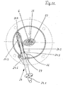
- FIGS. 11 and 12 show two positions of a locking device.
- the impeller (7) consists in the present case of a rigidly connected to the drive shaft agitator blade.
- the device for locking the agitator blade (7) has a with the drive shaft (6) coupled cam member (23) and a cooperating with this locking lever (24).
- the cam member (23) is fixed by means of a Reduzierhülse (25) on the drive shaft and its longitudinal direction corresponds to that of the stirring blade (7).
- the total here rotatable and axially movable locking lever (24) consists of a handle (24.1), one of the locking lever (24) interspersed disc (24.5), one on the one hand against the disc (24.5) and on the other hand inside a sleeve (24.3) supporting spring (24.2), wherein the sleeve (24.3) by means of a lock nut (24.4) on the locking lever (24) is fixed.
- a lever arm (24.6) is further attached, which defines on a support surface (27) at least two positions of the locking lever (24).
- the disc (24.5) slides on adjustment of the Arretierhebls (24) along a curved path (26).
- the locking of the impeller can be achieved during the rest position of the drive shaft (6) by a slight pressure on the locking lever (24) on the cam member (23).
- the elliptical shape of the cam member (23) thereby supports the orientation of the stirring blade (7), which is fixed to the drive shaft (6). If the drive shaft (6) is in the final phase of its rotational movement, it can be brought to a standstill via the locking lever (24), wherein the locking lever (24) is then axially parallel to the agitating blade and on the longitudinal side of the cam member (23) for conditioning comes.
Landscapes
- Life Sciences & Earth Sciences (AREA)
- Soil Sciences (AREA)
- Environmental Sciences (AREA)
- Mixers Of The Rotary Stirring Type (AREA)
- Pressure Vessels And Lids Thereof (AREA)
- Handcart (AREA)
- Treatment Of Sludge (AREA)
- Food-Manufacturing Devices (AREA)
- Table Equipment (AREA)
- Catching Or Destruction (AREA)
Applications Claiming Priority (2)
| Application Number | Priority Date | Filing Date | Title |
|---|---|---|---|
| DE19851598A DE19851598C2 (de) | 1998-11-09 | 1998-11-09 | Transportables Kleinrührwerk |
| DE19851598 | 1998-11-09 |
Publications (3)
| Publication Number | Publication Date |
|---|---|
| EP1000532A2 EP1000532A2 (de) | 2000-05-17 |
| EP1000532A3 EP1000532A3 (de) | 2002-01-23 |
| EP1000532B1 true EP1000532B1 (de) | 2006-05-31 |
Family
ID=7887166
Family Applications (1)
| Application Number | Title | Priority Date | Filing Date |
|---|---|---|---|
| EP99122207A Expired - Lifetime EP1000532B1 (de) | 1998-11-09 | 1999-11-06 | Transportables Kleinrührwerk |
Country Status (4)
| Country | Link |
|---|---|
| EP (1) | EP1000532B1 (da) |
| AT (1) | ATE327660T1 (da) |
| DE (2) | DE19851598C2 (da) |
| DK (1) | DK1000532T3 (da) |
Families Citing this family (3)
| Publication number | Priority date | Publication date | Assignee | Title |
|---|---|---|---|---|
| DE10252920A1 (de) * | 2002-11-12 | 2004-07-29 | Brand Gülletechnik GmbH | Kleinrührwerk |
| EP1782882B1 (de) | 2005-11-04 | 2011-06-22 | Brand Gülletechnik GmbH | Vorrichtung zum Rühren und Abpumpen von Gülle |
| CN120094461A (zh) * | 2025-05-07 | 2025-06-06 | 寿光市科瑞农业科技发展有限公司 | 一种肥料混合搅拌设备 |
Family Cites Families (8)
| Publication number | Priority date | Publication date | Assignee | Title |
|---|---|---|---|---|
| DE1831011U (de) * | 1960-11-18 | 1961-05-10 | Eduard Mayer | Hoehenverstellung fuer jaucheruehrwerk-wagen. |
| CH408502A (de) * | 1961-11-22 | 1966-02-28 | Ernst Lanz Maschinenfabrik Fa | Jaucherührwerk |
| DE2420605A1 (de) * | 1974-04-27 | 1975-11-06 | Hoess Walter | Jauche - ruehrwerk |
| CH644279A5 (en) * | 1979-12-17 | 1984-07-31 | Wilhelm Grotz | Stirring appliance, especially for liquid manure |
| DE3930576A1 (de) * | 1989-09-13 | 1991-03-14 | Wilhelm Grotz | Guelleruehrgeraet |
| FR2668217B1 (fr) * | 1990-10-17 | 1995-03-10 | Peugeot | Palier de guidage en rotation avec gorge de lubrification a section variable. |
| DK5892D0 (da) * | 1992-01-17 | 1992-01-17 | Kaj Egholm | Redskab til at findele ansamlinger paa overflader af gylle |
| US5358342A (en) * | 1992-12-17 | 1994-10-25 | Case Corporation | Pivot assembly with gravity lubrication feature |
-
1998
- 1998-11-09 DE DE19851598A patent/DE19851598C2/de not_active Expired - Fee Related
-
1999
- 1999-11-06 AT AT99122207T patent/ATE327660T1/de active
- 1999-11-06 DK DK99122207T patent/DK1000532T3/da active
- 1999-11-06 DE DE59913485T patent/DE59913485D1/de not_active Expired - Lifetime
- 1999-11-06 EP EP99122207A patent/EP1000532B1/de not_active Expired - Lifetime
Also Published As
| Publication number | Publication date |
|---|---|
| EP1000532A2 (de) | 2000-05-17 |
| DE19851598A1 (de) | 2000-05-25 |
| DE19851598C2 (de) | 2001-05-17 |
| DK1000532T3 (da) | 2006-09-25 |
| DE59913485D1 (de) | 2006-07-06 |
| EP1000532A3 (de) | 2002-01-23 |
| ATE327660T1 (de) | 2006-06-15 |
Similar Documents
| Publication | Publication Date | Title |
|---|---|---|
| DE2213779A1 (de) | Vorrichtung für die Demontage und Montage von Reifen | |
| DE69212971T2 (de) | Schwenkbarer Sitzaufbau mit Verriegelungseinrichtung | |
| DE69117277T2 (de) | Schleppfahrzeug für flugzeug | |
| DE69808170T2 (de) | Drehbarer, demontierbarer und klappbarer Lademast | |
| DE2018820A1 (de) | Verriegelungsvorrichtung an einem TeleskopausIe ger | |
| EP1000532B1 (de) | Transportables Kleinrührwerk | |
| EP3158907B1 (de) | Klapp- und schwenkbarer stützklappgriff, insbesondere für den sanitärbereich | |
| DE2929782C2 (de) | Vorrichtung zum Ausschneiden und Transportieren eines Gärfutterblockes | |
| EP3843522B1 (de) | Landwirtschaftliche maschine mit teleskoprahmen | |
| EP4457119B1 (de) | Klappsitz für ein fahrzeug | |
| DE3147543A1 (de) | Ausziehbare deichsel | |
| EP1419684B1 (de) | Kleinrührwerk | |
| EP2319286B1 (de) | Rührwerk und Verfahren zum Verrühren und Abpumpen Feststoffe enthaltender Flüssigkeiten | |
| DE1430433A1 (de) | Bewegbare Ladebuehnenanordnung | |
| EP0481114A1 (de) | Entriegelbares Kipplager der Kippbrücke eines Dreiseitenkippers | |
| DE102009039053B3 (de) | Vorrichtung zum Spalten von Holz | |
| EP0937377B1 (de) | Vorrichtung zum Homogenisieren von Gülle | |
| DE3229382C2 (da) | ||
| EP1300285A1 (de) | Anordnung zur Halterung unterschiedlicher Container-Typen auf einem Fahrgestell | |
| DE2227430A1 (de) | Hubeinrichtung fuer schwere lasten wie container und wechselbruecken | |
| DE3544497C2 (da) | ||
| DE3153007C2 (da) | ||
| EP1782882A1 (de) | Vorrichtung zum Rühren und Abpumpen von Gülle | |
| DE29910714U1 (de) | Bodenprobenentnahmegerät | |
| DE202024106747U1 (de) | Alarmvorrichtung gegen Kollisionen für schwere Kipperfahrzeuge im Bergbau |
Legal Events
| Date | Code | Title | Description |
|---|---|---|---|
| PUAI | Public reference made under article 153(3) epc to a published international application that has entered the european phase |
Free format text: ORIGINAL CODE: 0009012 |
|
| AK | Designated contracting states |
Kind code of ref document: A2 Designated state(s): AT BE CH CY DE DK ES FI FR GB GR IE IT LI LU MC NL PT SE |
|
| AX | Request for extension of the european patent |
Free format text: AL;LT;LV;MK;RO;SI |
|
| PUAL | Search report despatched |
Free format text: ORIGINAL CODE: 0009013 |
|
| AK | Designated contracting states |
Kind code of ref document: A3 Designated state(s): AT BE CH CY DE DK ES FI FR GB GR IE IT LI LU MC NL PT SE |
|
| AX | Request for extension of the european patent |
Free format text: AL;LT;LV;MK;RO;SI |
|
| RIC1 | Information provided on ipc code assigned before grant |
Free format text: 7A 01C 3/02 A, 7F 16C 33/10 B |
|
| 17P | Request for examination filed |
Effective date: 20020611 |
|
| AKX | Designation fees paid |
Free format text: AT BE CH CY DE DK ES FI FR GB GR IE IT LI LU MC NL PT SE |
|
| AXX | Extension fees paid |
Free format text: LT PAYMENT 20020611;LV PAYMENT 20020611;RO PAYMENT 20020611;SI PAYMENT 20020611 |
|
| 17Q | First examination report despatched |
Effective date: 20041022 |
|
| RAP1 | Party data changed (applicant data changed or rights of an application transferred) |
Owner name: BRAND GUELLETECHNIK GMBH |
|
| GRAP | Despatch of communication of intention to grant a patent |
Free format text: ORIGINAL CODE: EPIDOSNIGR1 |
|
| GRAS | Grant fee paid |
Free format text: ORIGINAL CODE: EPIDOSNIGR3 |
|
| GRAA | (expected) grant |
Free format text: ORIGINAL CODE: 0009210 |
|
| AK | Designated contracting states |
Kind code of ref document: B1 Designated state(s): AT BE CH CY DE DK ES FI FR GB GR IE IT LI LU MC NL PT SE |
|
| AX | Request for extension of the european patent |
Extension state: LT LV RO SI |
|
| PG25 | Lapsed in a contracting state [announced via postgrant information from national office to epo] |
Ref country code: IT Free format text: LAPSE BECAUSE OF FAILURE TO SUBMIT A TRANSLATION OF THE DESCRIPTION OR TO PAY THE FEE WITHIN THE PRE;WARNING: LAPSES OF ITALIAN PATENTS WITH EFFECTIVE DATE BEFORE 2007 MAY HAVE OCCURRED AT ANY TIME BEFORE 2007. THE CORRECT EFFECTIVE DATE MAY BE DIFFERENT FROM THE ONE RECORDED.SCRIBED TIME-LIMIT Effective date: 20060531 Ref country code: IE Free format text: LAPSE BECAUSE OF FAILURE TO SUBMIT A TRANSLATION OF THE DESCRIPTION OR TO PAY THE FEE WITHIN THE PRESCRIBED TIME-LIMIT Effective date: 20060531 Ref country code: FI Free format text: LAPSE BECAUSE OF FAILURE TO SUBMIT A TRANSLATION OF THE DESCRIPTION OR TO PAY THE FEE WITHIN THE PRESCRIBED TIME-LIMIT Effective date: 20060531 |
|
| REG | Reference to a national code |
Ref country code: CH Ref legal event code: NV Representative=s name: KATZAROV S.A. Ref country code: GB Ref legal event code: FG4D Free format text: NOT ENGLISH Ref country code: CH Ref legal event code: EP |
|
| REG | Reference to a national code |
Ref country code: IE Ref legal event code: FG4D Free format text: LANGUAGE OF EP DOCUMENT: GERMAN |
|
| REF | Corresponds to: |
Ref document number: 59913485 Country of ref document: DE Date of ref document: 20060706 Kind code of ref document: P |
|
| GBT | Gb: translation of ep patent filed (gb section 77(6)(a)/1977) |
Effective date: 20060712 |
|
| PG25 | Lapsed in a contracting state [announced via postgrant information from national office to epo] |
Ref country code: SE Free format text: LAPSE BECAUSE OF FAILURE TO SUBMIT A TRANSLATION OF THE DESCRIPTION OR TO PAY THE FEE WITHIN THE PRESCRIBED TIME-LIMIT Effective date: 20060831 |
|
| PG25 | Lapsed in a contracting state [announced via postgrant information from national office to epo] |
Ref country code: ES Free format text: LAPSE BECAUSE OF FAILURE TO SUBMIT A TRANSLATION OF THE DESCRIPTION OR TO PAY THE FEE WITHIN THE PRESCRIBED TIME-LIMIT Effective date: 20060911 |
|
| REG | Reference to a national code |
Ref country code: DK Ref legal event code: T3 |
|
| PG25 | Lapsed in a contracting state [announced via postgrant information from national office to epo] |
Ref country code: PT Free format text: LAPSE BECAUSE OF FAILURE TO SUBMIT A TRANSLATION OF THE DESCRIPTION OR TO PAY THE FEE WITHIN THE PRESCRIBED TIME-LIMIT Effective date: 20061031 |
|
| PGFP | Annual fee paid to national office [announced via postgrant information from national office to epo] |
Ref country code: GB Payment date: 20061106 Year of fee payment: 8 |
|
| LTIE | Lt: invalidation of european patent or patent extension |
Effective date: 20060531 |
|
| PG25 | Lapsed in a contracting state [announced via postgrant information from national office to epo] |
Ref country code: MC Free format text: LAPSE BECAUSE OF NON-PAYMENT OF DUE FEES Effective date: 20061130 |
|
| REG | Reference to a national code |
Ref country code: IE Ref legal event code: FD4D |
|
| ET | Fr: translation filed | ||
| PGFP | Annual fee paid to national office [announced via postgrant information from national office to epo] |
Ref country code: CH Payment date: 20070221 Year of fee payment: 8 |
|
| PLBI | Opposition filed |
Free format text: ORIGINAL CODE: 0009260 |
|
| PLAX | Notice of opposition and request to file observation + time limit sent |
Free format text: ORIGINAL CODE: EPIDOSNOBS2 |
|
| 26 | Opposition filed |
Opponent name: KIRCHNER & SOEHNE GMBH Effective date: 20070220 |
|
| NLR1 | Nl: opposition has been filed with the epo |
Opponent name: KIRCHNER & SOEHNE GMBH |
|
| PLBB | Reply of patent proprietor to notice(s) of opposition received |
Free format text: ORIGINAL CODE: EPIDOSNOBS3 |
|
| PG25 | Lapsed in a contracting state [announced via postgrant information from national office to epo] |
Ref country code: GR Free format text: LAPSE BECAUSE OF FAILURE TO SUBMIT A TRANSLATION OF THE DESCRIPTION OR TO PAY THE FEE WITHIN THE PRESCRIBED TIME-LIMIT Effective date: 20060901 |
|
| PGFP | Annual fee paid to national office [announced via postgrant information from national office to epo] |
Ref country code: FR Payment date: 20071115 Year of fee payment: 9 |
|
| GBPC | Gb: european patent ceased through non-payment of renewal fee |
Effective date: 20071106 |
|
| PG25 | Lapsed in a contracting state [announced via postgrant information from national office to epo] |
Ref country code: LI Free format text: LAPSE BECAUSE OF NON-PAYMENT OF DUE FEES Effective date: 20071130 Ref country code: CH Free format text: LAPSE BECAUSE OF NON-PAYMENT OF DUE FEES Effective date: 20071130 Ref country code: LU Free format text: LAPSE BECAUSE OF NON-PAYMENT OF DUE FEES Effective date: 20061106 |
|
| REG | Reference to a national code |
Ref country code: CH Ref legal event code: PL |
|
| PG25 | Lapsed in a contracting state [announced via postgrant information from national office to epo] |
Ref country code: CY Free format text: LAPSE BECAUSE OF FAILURE TO SUBMIT A TRANSLATION OF THE DESCRIPTION OR TO PAY THE FEE WITHIN THE PRESCRIBED TIME-LIMIT Effective date: 20060531 |
|
| PG25 | Lapsed in a contracting state [announced via postgrant information from national office to epo] |
Ref country code: GB Free format text: LAPSE BECAUSE OF NON-PAYMENT OF DUE FEES Effective date: 20071106 |
|
| REG | Reference to a national code |
Ref country code: FR Ref legal event code: ST Effective date: 20090731 |
|
| PLAB | Opposition data, opponent's data or that of the opponent's representative modified |
Free format text: ORIGINAL CODE: 0009299OPPO |
|
| R26 | Opposition filed (corrected) |
Opponent name: KIRCHNER & SOEHNE GMBH Effective date: 20070220 |
|
| PLBP | Opposition withdrawn |
Free format text: ORIGINAL CODE: 0009264 |
|
| PLBD | Termination of opposition procedure: decision despatched |
Free format text: ORIGINAL CODE: EPIDOSNOPC1 |
|
| PLBM | Termination of opposition procedure: date of legal effect published |
Free format text: ORIGINAL CODE: 0009276 |
|
| STAA | Information on the status of an ep patent application or granted ep patent |
Free format text: STATUS: OPPOSITION PROCEDURE CLOSED |
|
| PGFP | Annual fee paid to national office [announced via postgrant information from national office to epo] |
Ref country code: NL Payment date: 20101126 Year of fee payment: 12 Ref country code: DK Payment date: 20101117 Year of fee payment: 12 |
|
| 27C | Opposition proceedings terminated |
Effective date: 20100924 |
|
| PG25 | Lapsed in a contracting state [announced via postgrant information from national office to epo] |
Ref country code: FR Free format text: LAPSE BECAUSE OF NON-PAYMENT OF DUE FEES Effective date: 20081130 |
|
| REG | Reference to a national code |
Ref country code: NL Ref legal event code: V1 Effective date: 20120601 |
|
| REG | Reference to a national code |
Ref country code: DK Ref legal event code: EBP |
|
| PG25 | Lapsed in a contracting state [announced via postgrant information from national office to epo] |
Ref country code: NL Free format text: LAPSE BECAUSE OF NON-PAYMENT OF DUE FEES Effective date: 20120601 |
|
| PG25 | Lapsed in a contracting state [announced via postgrant information from national office to epo] |
Ref country code: DK Free format text: LAPSE BECAUSE OF NON-PAYMENT OF DUE FEES Effective date: 20111130 |
|
| REG | Reference to a national code |
Ref country code: DE Ref legal event code: R082 Ref document number: 59913485 Country of ref document: DE Representative=s name: HUETTNER, TORALF, DIPL.-ING., DE |
|
| REG | Reference to a national code |
Ref country code: DE Ref legal event code: R082 Ref document number: 59913485 Country of ref document: DE Representative=s name: HUETTNER, TORALF, DIPL.-ING., DE Effective date: 20130429 Ref country code: DE Ref legal event code: R081 Ref document number: 59913485 Country of ref document: DE Owner name: BRAND RUEHR- UND PUMPTECHNIK GMBH, DE Free format text: FORMER OWNER: BRAND GUELLETECHNIK GMBH, 49176 HILTER, DE Effective date: 20130429 |
|
| PGFP | Annual fee paid to national office [announced via postgrant information from national office to epo] |
Ref country code: BE Payment date: 20141125 Year of fee payment: 16 |
|
| PG25 | Lapsed in a contracting state [announced via postgrant information from national office to epo] |
Ref country code: BE Free format text: LAPSE BECAUSE OF NON-PAYMENT OF DUE FEES Effective date: 20151130 |
|
| PGFP | Annual fee paid to national office [announced via postgrant information from national office to epo] |
Ref country code: DE Payment date: 20181025 Year of fee payment: 20 Ref country code: AT Payment date: 20181120 Year of fee payment: 20 |
|
| REG | Reference to a national code |
Ref country code: DE Ref legal event code: R071 Ref document number: 59913485 Country of ref document: DE |
|
| REG | Reference to a national code |
Ref country code: AT Ref legal event code: MK07 Ref document number: 327660 Country of ref document: AT Kind code of ref document: T Effective date: 20191106 |