EP1000654A2 - Plaque intercalaire pour utilisation dans des procédés de séparation à membranes - Google Patents
Plaque intercalaire pour utilisation dans des procédés de séparation à membranes Download PDFInfo
- Publication number
- EP1000654A2 EP1000654A2 EP99811022A EP99811022A EP1000654A2 EP 1000654 A2 EP1000654 A2 EP 1000654A2 EP 99811022 A EP99811022 A EP 99811022A EP 99811022 A EP99811022 A EP 99811022A EP 1000654 A2 EP1000654 A2 EP 1000654A2
- Authority
- EP
- European Patent Office
- Prior art keywords
- shaped
- plate
- membrane
- membranes
- line
- Prior art date
- Legal status (The legal status is an assumption and is not a legal conclusion. Google has not performed a legal analysis and makes no representation as to the accuracy of the status listed.)
- Withdrawn
Links
Images

Classifications
-
- B—PERFORMING OPERATIONS; TRANSPORTING
- B01—PHYSICAL OR CHEMICAL PROCESSES OR APPARATUS IN GENERAL
- B01D—SEPARATION
- B01D63/00—Apparatus in general for separation processes using semi-permeable membranes
- B01D63/08—Flat membrane modules
- B01D63/082—Flat membrane modules comprising a stack of flat membranes
- B01D63/0822—Plate-and-frame devices
-
- B—PERFORMING OPERATIONS; TRANSPORTING
- B01—PHYSICAL OR CHEMICAL PROCESSES OR APPARATUS IN GENERAL
- B01D—SEPARATION
- B01D61/00—Processes of separation using semi-permeable membranes, e.g. dialysis, osmosis or ultrafiltration; Apparatus, accessories or auxiliary operations specially adapted therefor
- B01D61/42—Electrodialysis; Electro-osmosis ; Electro-ultrafiltration; Membrane capacitive deionization
- B01D61/44—Ion-selective electrodialysis
- B01D61/46—Apparatus therefor
- B01D61/50—Stacks of the plate-and-frame type
-
- B—PERFORMING OPERATIONS; TRANSPORTING
- B01—PHYSICAL OR CHEMICAL PROCESSES OR APPARATUS IN GENERAL
- B01D—SEPARATION
- B01D63/00—Apparatus in general for separation processes using semi-permeable membranes
- B01D63/08—Flat membrane modules
- B01D63/082—Flat membrane modules comprising a stack of flat membranes
- B01D63/084—Flat membrane modules comprising a stack of flat membranes at least one flow duct intersecting the membranes
-
- B—PERFORMING OPERATIONS; TRANSPORTING
- B01—PHYSICAL OR CHEMICAL PROCESSES OR APPARATUS IN GENERAL
- B01D—SEPARATION
- B01D63/00—Apparatus in general for separation processes using semi-permeable membranes
- B01D63/08—Flat membrane modules
- B01D63/082—Flat membrane modules comprising a stack of flat membranes
- B01D63/084—Flat membrane modules comprising a stack of flat membranes at least one flow duct intersecting the membranes
- B01D63/085—Flat membrane modules comprising a stack of flat membranes at least one flow duct intersecting the membranes specially adapted for two fluids in mass exchange flow
Definitions
- the invention relates to a plate-shaped spacer for use in membrane separation processes, with bilateral contact surfaces for membranes, whereby for At least flow to the membranes with a medium to be separated in the spacer a line-shaped extending from an inlet to an outlet Recess with an at least partially curved course is provided and the linear recess with the membrane placed on it is a tubular, forms a closed flow channel.
- spacers used in membrane separation processes serve as spacers and at the same time for flow guidance.
- Spacers of known design exist for example from a fabric or they are produced by extrusion.
- Woven spacers are characterized by point contact and extruded Spacer through a linear contact with the membrane surface out. Both types of spacers result in a relatively low separation performance based on the flow to the membrane surface. In addition, the flow pressure losses usually high.
- a spacer of the type mentioned at the outset is disclosed in EP-B 0422137.
- the Flow channel is in the form of a spiral groove in the membrane contact surface of the Spacers arranged.
- the spacer has two to increase the separation performance Membrane support surfaces, each of the support surfaces with a spiral Groove is equipped and the two grooves over holes with each other are connected.
- This type of spacer results from the curved Flow channel through the formation of Dean vortices a stabilization laminar flow. Under these hydrodynamic conditions Mass transfer resistances reduced and deposits on membrane surfaces prevented.
- the invention has for its object a spacer of the aforementioned To create a type that is structurally simple and has a high separation performance contributes to membrane separation processes.
- the linear Recess than connecting the two membrane contact surfaces line-shaped breakthrough and the tubular, closed Flow channel with membranes placed on both sides bounded by membranes is.
- the linear breakthrough is thus a bilaterally open, at least partially curved flow channel, which with applied membranes to leads tubular, closed flow channel.
- Flow channel results in a simple manufacture of the significant advantage that the area is not limited by a membrane of the flow channel is reduced, resulting in a decrease in through the channel walls caused flow resistance.
- the one in the curved channel formed Dean vertebrae are used on both sides.
- the linear opening is preferably meandering and can for example from essentially parallel, essentially straight sections and from the flow direction deflecting areas of curvature be educated.
- the arranged between the curvature regions deflecting the flow direction Partial areas also curved. By bending these sections is achieved that the deflecting in the flow direction Areas of curvature are formed which stabilize the laminar flow Don't break the vertebrae.
- the meandering arrangement of the flow channel has in addition to the simple Manufacture the advantage that inlet and outlet openings in the area of Spacer edges can be arranged, which is also the structural design relieved by equipment.
- the line-shaped opening can also be designed in a spiral.
- the line-shaped opening is wave-shaped and there are several breakthroughs in parallel.
- the line-shaped Breakthrough in applied membrane s a flow channel with an im essentially rectangular, preferably square cross-section.
- the line-shaped breakthrough can be that only minimally hinder the flow, be stabilized.
- the support bars can turn out to be useful when installing separation modules. Basically support bars can be dispensed with, however, because the canal walls pass through the membrane supports are clamped.
- the field of application of the plate-shaped spacer according to the invention extends to all membrane separation processes, especially membrane separation processes for electrodialysis, pervaporation, micro and ultrafiltration.
- a plate-shaped spacer 10 of rectangular shape shown in FIGS. 1 and 2 Shape has one in one of the corners arranged perpendicular to the plate plane Inlet bore 12 and a diametrically opposed one Drain hole 14 on. Is between the inlet bore 12 and the outlet bore 14 a meandering opening 16 is arranged. Breakthrough 16 consists of parallel, straight sections 18 which have terminal curvature areas 20 are connected.
- the flow channel formed by the meandering opening 16 has channel walls 22, each with a free end 24.
- This structure when assembling a separation module is the channel walls 22 connected to one another via support webs 26.
- the inlet bore 12 is at one end of the meandering opening 16 connected via a covered inlet channel 28.
- the two plate surfaces of the spacer 10 form contact surfaces 38, 40 for membranes not shown in the drawing.
- the use of the spacer 10 is the opening 16 through the overlying ones Membranes covered and leads to a rectangular, closed Flow channel.
- the connection between spacer 10 and overlying membranes is designed to be fluid-tight. In practice, for example achieved by gluing or by circumferential sealing webs or grooves.
- the subregions are 18 between the deflection regions 20 deflecting the flow likewise curved.
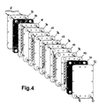
- FIG. 4 shows the use of the spacers 10 from FIG. 3 in an electrodialysis module. Between two end plates 32 and electrode plates adjoining them 34 are spacers 10 and carrier plates 36 in an alternating sequence arranged with the filter medium or the filter medium itself.
- the flow course through the electrodialysis module is represented by arrows.
- the Medium F (feed) to be dialyzed occurs on one side of the module and on the other side of the module after the separation process as retentate R or Diluate D.
Landscapes
- Chemical & Material Sciences (AREA)
- Chemical Kinetics & Catalysis (AREA)
- Engineering & Computer Science (AREA)
- Water Supply & Treatment (AREA)
- Health & Medical Sciences (AREA)
- Urology & Nephrology (AREA)
- Separation Using Semi-Permeable Membranes (AREA)
Applications Claiming Priority (2)
| Application Number | Priority Date | Filing Date | Title |
|---|---|---|---|
| CH227698 | 1998-11-12 | ||
| CH227698 | 1998-11-12 |
Publications (2)
| Publication Number | Publication Date |
|---|---|
| EP1000654A2 true EP1000654A2 (fr) | 2000-05-17 |
| EP1000654A3 EP1000654A3 (fr) | 2002-01-02 |
Family
ID=4229984
Family Applications (1)
| Application Number | Title | Priority Date | Filing Date |
|---|---|---|---|
| EP99811022A Withdrawn EP1000654A3 (fr) | 1998-11-12 | 1999-11-08 | Plaque intercalaire pour utilisation dans des procédés de séparation à membranes |
Country Status (1)
| Country | Link |
|---|---|
| EP (1) | EP1000654A3 (fr) |
Cited By (4)
| Publication number | Priority date | Publication date | Assignee | Title |
|---|---|---|---|---|
| SG116478A1 (en) * | 2003-02-11 | 2005-11-28 | Hyflux Ltd | Web structure membrane spacer. |
| WO2012095506A1 (fr) * | 2011-01-13 | 2012-07-19 | Jurag Separation A/S | Système de séparation à électro-membranes |
| WO2013079588A1 (fr) * | 2011-11-29 | 2013-06-06 | Henkel Ag & Co. Kgaa | Procédé de régénération de dispersions aqueuses et cellules chargées pour l'électrodialyse |
| WO2017021938A1 (fr) * | 2015-08-05 | 2017-02-09 | Wisewater Pte. Ltd | Entretoise de canal en spirale pour dispositifs d'empilement de membrane de sélectivité ionique |
Family Cites Families (5)
| Publication number | Priority date | Publication date | Assignee | Title |
|---|---|---|---|---|
| US4461693A (en) * | 1982-07-06 | 1984-07-24 | Ionics Incorporated | Polarity reversal electrodes |
| JPS6434406A (en) * | 1987-07-30 | 1989-02-03 | Kurita Machinery Manuf | Filtering and concentrating machine |
| EP0361499B1 (fr) * | 1988-09-30 | 1994-03-30 | Daikin Industries, Limited | Appareil pour la séparation de liquides |
| US5292422A (en) * | 1992-09-15 | 1994-03-08 | Ip Holding Company | Modules for electrodeionization apparatus |
| US5972191A (en) * | 1997-01-17 | 1999-10-26 | Archer Daniels Midland Company | Electrodialysis apparatus |
-
1999
- 1999-11-08 EP EP99811022A patent/EP1000654A3/fr not_active Withdrawn
Cited By (7)
| Publication number | Priority date | Publication date | Assignee | Title |
|---|---|---|---|---|
| SG116478A1 (en) * | 2003-02-11 | 2005-11-28 | Hyflux Ltd | Web structure membrane spacer. |
| WO2012095506A1 (fr) * | 2011-01-13 | 2012-07-19 | Jurag Separation A/S | Système de séparation à électro-membranes |
| CN103648619A (zh) * | 2011-01-13 | 2014-03-19 | 嘉士伯有限公司 | 电膜分离系统 |
| CN103648619B (zh) * | 2011-01-13 | 2015-11-25 | 嘉士伯有限公司 | 电膜分离系统 |
| EA025684B1 (ru) * | 2011-01-13 | 2017-01-30 | Карлсберг А/С | Электромембранная система разделения |
| WO2013079588A1 (fr) * | 2011-11-29 | 2013-06-06 | Henkel Ag & Co. Kgaa | Procédé de régénération de dispersions aqueuses et cellules chargées pour l'électrodialyse |
| WO2017021938A1 (fr) * | 2015-08-05 | 2017-02-09 | Wisewater Pte. Ltd | Entretoise de canal en spirale pour dispositifs d'empilement de membrane de sélectivité ionique |
Also Published As
| Publication number | Publication date |
|---|---|
| EP1000654A3 (fr) | 2002-01-02 |
Similar Documents
| Publication | Publication Date | Title |
|---|---|---|
| EP0805328B1 (fr) | Module d'écoulement | |
| DE60214968T2 (de) | Wärmeübertragungsplatte; plattenpackung und plattenwärmetauscher | |
| DE60009075T2 (de) | Wärmetauscherplatte | |
| EP3957940B1 (fr) | Module d'échangeur de chaleur à plaque à contre-courant et échangeur de chaleur à plaque à contre-courant | |
| DE4225060C1 (fr) | ||
| DE2406077C2 (de) | Diffusionsvorrichtung, | |
| DE3500571A1 (de) | Kuehler fuer kraftfahrzeuge | |
| DE102017206670A1 (de) | Bypassdichtung für Scheibenheizungsmatrix | |
| DE102021115559A1 (de) | Brennstoffzelle | |
| DE2209116A1 (de) | Filtervorrichtung | |
| EP0274058A2 (fr) | Echangeur de chaleur à plaques | |
| DE2951853C2 (fr) | ||
| DE2905001C2 (de) | Rohrbündelwärmetauscher | |
| DE69606410T2 (de) | Plattenwärmetauscher mit gestapelten platten, wobei diagonal gegenüberliegende ecken jeder platte versenkte eckenbereiche aufweisen | |
| AT393162B (de) | Plattenwaermeaustauscher mit besonderem profil der waermeaustauschzone | |
| EP1000654A2 (fr) | Plaque intercalaire pour utilisation dans des procédés de séparation à membranes | |
| EP0495184B1 (fr) | Echangeur de chaleur à plaques à écoulement à contre-courant | |
| DE102019210238A1 (de) | Stapelscheibenwärmetauscher | |
| DE2603505C3 (de) | Flachmembranmodul für umgekehrte Osmose und Ultrafiltration | |
| DE10130716A1 (de) | Wickelmodul zur Crossflow-Filtration | |
| EP0423857B1 (fr) | Procédé pour la production d'une tôle en U avec des tôles disposées parallèlement l'une à l'autre, dispositif pour la mise en oeuvre du procédé | |
| DE1211596B (de) | Einrichtung zur Dialyse, insbesondere Elektrodialyse | |
| DE3301211A1 (de) | Plattenwaermeaustauscher | |
| WO1999067591A1 (fr) | Echangeur de chaleur a plaques | |
| WO1998032583A1 (fr) | Dispositif pour produire des tubes a nervures transversales |
Legal Events
| Date | Code | Title | Description |
|---|---|---|---|
| PUAI | Public reference made under article 153(3) epc to a published international application that has entered the european phase |
Free format text: ORIGINAL CODE: 0009012 |
|
| AK | Designated contracting states |
Kind code of ref document: A2 Designated state(s): AT BE CH CY DE DK ES FI FR GB GR IE IT LI LU MC NL PT SE Kind code of ref document: A2 Designated state(s): CH DE FR GB LI NL |
|
| AX | Request for extension of the european patent |
Free format text: AL;LT;LV;MK;RO;SI |
|
| PUAL | Search report despatched |
Free format text: ORIGINAL CODE: 0009013 |
|
| AK | Designated contracting states |
Kind code of ref document: A3 Designated state(s): AT BE CH CY DE DK ES FI FR GB GR IE IT LI LU MC NL PT SE |
|
| AX | Request for extension of the european patent |
Free format text: AL;LT;LV;MK;RO;SI |
|
| 17P | Request for examination filed |
Effective date: 20020625 |
|
| AKX | Designation fees paid |
Free format text: AT BE CH CY DE LI |
|
| RBV | Designated contracting states (corrected) |
Designated state(s): CH DE FR GB LI NL |
|
| 17Q | First examination report despatched |
Effective date: 20021112 |
|
| STAA | Information on the status of an ep patent application or granted ep patent |
Free format text: STATUS: THE APPLICATION IS DEEMED TO BE WITHDRAWN |
|
| 18D | Application deemed to be withdrawn |
Effective date: 20030323 |