EP1000656A1 - Mischer für einen Extruder mit schwimmenden Ringen - Google Patents
Mischer für einen Extruder mit schwimmenden Ringen Download PDFInfo
- Publication number
- EP1000656A1 EP1000656A1 EP99307428A EP99307428A EP1000656A1 EP 1000656 A1 EP1000656 A1 EP 1000656A1 EP 99307428 A EP99307428 A EP 99307428A EP 99307428 A EP99307428 A EP 99307428A EP 1000656 A1 EP1000656 A1 EP 1000656A1
- Authority
- EP
- European Patent Office
- Prior art keywords
- driven
- rings
- polymer melt
- ring
- rotor
- Prior art date
- Legal status (The legal status is an assumption and is not a legal conclusion. Google has not performed a legal analysis and makes no representation as to the accuracy of the status listed.)
- Withdrawn
Links
- 238000007667 floating Methods 0.000 title claims abstract description 63
- 229920000642 polymer Polymers 0.000 claims abstract description 93
- 238000011144 upstream manufacturing Methods 0.000 claims abstract description 36
- 230000000694 effects Effects 0.000 claims abstract description 14
- 238000010008 shearing Methods 0.000 claims abstract description 6
- 238000000034 method Methods 0.000 claims description 4
- 230000002093 peripheral effect Effects 0.000 claims 1
- 239000000155 melt Substances 0.000 abstract description 5
- 238000002347 injection Methods 0.000 description 9
- 239000007924 injection Substances 0.000 description 9
- 238000001125 extrusion Methods 0.000 description 3
- 238000001746 injection moulding Methods 0.000 description 3
- 238000013459 approach Methods 0.000 description 2
- 125000006850 spacer group Chemical group 0.000 description 2
- 238000012546 transfer Methods 0.000 description 2
- 239000000470 constituent Substances 0.000 description 1
- 238000010276 construction Methods 0.000 description 1
- 230000000977 initiatory effect Effects 0.000 description 1
- 238000012423 maintenance Methods 0.000 description 1
- 238000004519 manufacturing process Methods 0.000 description 1
- 239000000289 melt material Substances 0.000 description 1
- 238000002844 melting Methods 0.000 description 1
- 230000008018 melting Effects 0.000 description 1
- 238000012986 modification Methods 0.000 description 1
- 230000004048 modification Effects 0.000 description 1
- 238000007789 sealing Methods 0.000 description 1
- 230000003068 static effect Effects 0.000 description 1
Images
Classifications
-
- B—PERFORMING OPERATIONS; TRANSPORTING
- B29—WORKING OF PLASTICS; WORKING OF SUBSTANCES IN A PLASTIC STATE IN GENERAL
- B29C—SHAPING OR JOINING OF PLASTICS; SHAPING OF MATERIAL IN A PLASTIC STATE, NOT OTHERWISE PROVIDED FOR; AFTER-TREATMENT OF THE SHAPED PRODUCTS, e.g. REPAIRING
- B29C45/00—Injection moulding, i.e. forcing the required volume of moulding material through a nozzle into a closed mould; Apparatus therefor
- B29C45/17—Component parts, details or accessories; Auxiliary operations
- B29C45/46—Means for plasticising or homogenising the moulding material or forcing it into the mould
- B29C45/47—Means for plasticising or homogenising the moulding material or forcing it into the mould using screws
- B29C45/50—Axially movable screw
- B29C45/52—Non-return devices
-
- B—PERFORMING OPERATIONS; TRANSPORTING
- B29—WORKING OF PLASTICS; WORKING OF SUBSTANCES IN A PLASTIC STATE IN GENERAL
- B29B—PREPARATION OR PRETREATMENT OF THE MATERIAL TO BE SHAPED; MAKING GRANULES OR PREFORMS; RECOVERY OF PLASTICS OR OTHER CONSTITUENTS OF WASTE MATERIAL CONTAINING PLASTICS
- B29B7/00—Mixing; Kneading
- B29B7/30—Mixing; Kneading continuous, with mechanical mixing or kneading devices
- B29B7/34—Mixing; Kneading continuous, with mechanical mixing or kneading devices with movable mixing or kneading devices
- B29B7/38—Mixing; Kneading continuous, with mechanical mixing or kneading devices with movable mixing or kneading devices rotary
- B29B7/40—Mixing; Kneading continuous, with mechanical mixing or kneading devices with movable mixing or kneading devices rotary with single shaft
- B29B7/42—Mixing; Kneading continuous, with mechanical mixing or kneading devices with movable mixing or kneading devices rotary with single shaft with screw or helix
- B29B7/421—Mixing; Kneading continuous, with mechanical mixing or kneading devices with movable mixing or kneading devices rotary with single shaft with screw or helix with screw and additionally other mixing elements on the same shaft, e.g. paddles, discs, bearings, rotor blades of the Banbury type
-
- B—PERFORMING OPERATIONS; TRANSPORTING
- B29—WORKING OF PLASTICS; WORKING OF SUBSTANCES IN A PLASTIC STATE IN GENERAL
- B29C—SHAPING OR JOINING OF PLASTICS; SHAPING OF MATERIAL IN A PLASTIC STATE, NOT OTHERWISE PROVIDED FOR; AFTER-TREATMENT OF THE SHAPED PRODUCTS, e.g. REPAIRING
- B29C48/00—Extrusion moulding, i.e. expressing the moulding material through a die or nozzle which imparts the desired form; Apparatus therefor
- B29C48/25—Component parts, details or accessories; Auxiliary operations
- B29C48/36—Means for plasticising or homogenising the moulding material or forcing it through the nozzle or die
- B29C48/395—Means for plasticising or homogenising the moulding material or forcing it through the nozzle or die using screws surrounded by a cooperating barrel, e.g. single screw extruders
-
- B—PERFORMING OPERATIONS; TRANSPORTING
- B29—WORKING OF PLASTICS; WORKING OF SUBSTANCES IN A PLASTIC STATE IN GENERAL
- B29C—SHAPING OR JOINING OF PLASTICS; SHAPING OF MATERIAL IN A PLASTIC STATE, NOT OTHERWISE PROVIDED FOR; AFTER-TREATMENT OF THE SHAPED PRODUCTS, e.g. REPAIRING
- B29C48/00—Extrusion moulding, i.e. expressing the moulding material through a die or nozzle which imparts the desired form; Apparatus therefor
- B29C48/25—Component parts, details or accessories; Auxiliary operations
- B29C48/36—Means for plasticising or homogenising the moulding material or forcing it through the nozzle or die
- B29C48/50—Details of extruders
- B29C48/505—Screws
- B29C48/56—Screws having grooves or cavities other than the thread or the channel
-
- B—PERFORMING OPERATIONS; TRANSPORTING
- B29—WORKING OF PLASTICS; WORKING OF SUBSTANCES IN A PLASTIC STATE IN GENERAL
- B29C—SHAPING OR JOINING OF PLASTICS; SHAPING OF MATERIAL IN A PLASTIC STATE, NOT OTHERWISE PROVIDED FOR; AFTER-TREATMENT OF THE SHAPED PRODUCTS, e.g. REPAIRING
- B29C48/00—Extrusion moulding, i.e. expressing the moulding material through a die or nozzle which imparts the desired form; Apparatus therefor
- B29C48/25—Component parts, details or accessories; Auxiliary operations
- B29C48/36—Means for plasticising or homogenising the moulding material or forcing it through the nozzle or die
- B29C48/50—Details of extruders
- B29C48/505—Screws
- B29C48/565—Screws having projections other than the thread, e.g. pins
-
- B—PERFORMING OPERATIONS; TRANSPORTING
- B29—WORKING OF PLASTICS; WORKING OF SUBSTANCES IN A PLASTIC STATE IN GENERAL
- B29C—SHAPING OR JOINING OF PLASTICS; SHAPING OF MATERIAL IN A PLASTIC STATE, NOT OTHERWISE PROVIDED FOR; AFTER-TREATMENT OF THE SHAPED PRODUCTS, e.g. REPAIRING
- B29C48/00—Extrusion moulding, i.e. expressing the moulding material through a die or nozzle which imparts the desired form; Apparatus therefor
- B29C48/25—Component parts, details or accessories; Auxiliary operations
- B29C48/36—Means for plasticising or homogenising the moulding material or forcing it through the nozzle or die
- B29C48/50—Details of extruders
- B29C48/68—Barrels or cylinders
- B29C48/685—Barrels or cylinders characterised by their inner surfaces, e.g. having grooves, projections or threads
- B29C48/686—Barrels or cylinders characterised by their inner surfaces, e.g. having grooves, projections or threads having grooves or cavities
-
- B—PERFORMING OPERATIONS; TRANSPORTING
- B29—WORKING OF PLASTICS; WORKING OF SUBSTANCES IN A PLASTIC STATE IN GENERAL
- B29C—SHAPING OR JOINING OF PLASTICS; SHAPING OF MATERIAL IN A PLASTIC STATE, NOT OTHERWISE PROVIDED FOR; AFTER-TREATMENT OF THE SHAPED PRODUCTS, e.g. REPAIRING
- B29C45/00—Injection moulding, i.e. forcing the required volume of moulding material through a nozzle into a closed mould; Apparatus therefor
- B29C45/17—Component parts, details or accessories; Auxiliary operations
- B29C45/46—Means for plasticising or homogenising the moulding material or forcing it into the mould
- B29C45/47—Means for plasticising or homogenising the moulding material or forcing it into the mould using screws
- B29C45/50—Axially movable screw
- B29C45/52—Non-return devices
- B29C2045/528—Mixing means forming part of or in close proximity to the non-return valve
-
- B—PERFORMING OPERATIONS; TRANSPORTING
- B29—WORKING OF PLASTICS; WORKING OF SUBSTANCES IN A PLASTIC STATE IN GENERAL
- B29C—SHAPING OR JOINING OF PLASTICS; SHAPING OF MATERIAL IN A PLASTIC STATE, NOT OTHERWISE PROVIDED FOR; AFTER-TREATMENT OF THE SHAPED PRODUCTS, e.g. REPAIRING
- B29C45/00—Injection moulding, i.e. forcing the required volume of moulding material through a nozzle into a closed mould; Apparatus therefor
- B29C45/17—Component parts, details or accessories; Auxiliary operations
- B29C45/46—Means for plasticising or homogenising the moulding material or forcing it into the mould
- B29C45/58—Details
- B29C45/581—Devices for influencing the material flow, e.g. "torpedo constructions" or mixing devices
-
- B—PERFORMING OPERATIONS; TRANSPORTING
- B29—WORKING OF PLASTICS; WORKING OF SUBSTANCES IN A PLASTIC STATE IN GENERAL
- B29C—SHAPING OR JOINING OF PLASTICS; SHAPING OF MATERIAL IN A PLASTIC STATE, NOT OTHERWISE PROVIDED FOR; AFTER-TREATMENT OF THE SHAPED PRODUCTS, e.g. REPAIRING
- B29C48/00—Extrusion moulding, i.e. expressing the moulding material through a die or nozzle which imparts the desired form; Apparatus therefor
- B29C48/03—Extrusion moulding, i.e. expressing the moulding material through a die or nozzle which imparts the desired form; Apparatus therefor characterised by the shape of the extruded material at extrusion
Definitions
- the present invention is in the field of polymer extruders and mixers for use in connection with providing high pressure polymer melts for injection moulding and extrusion and the like.
- a polymer melt mixer in a heated extruder barrel, sometimes referred to as a stator, including a bore defining a cylindrical internal chamber in which a screw rotor is axially positioned for a rotation within and with respect to the cylindrical chamber. It is also conventional to have the upstream portion of the rotor comprise a driven rotary screw member for feeding the polymer components along the length of the rotor or barrel to a downstream portion which provides mixing of the the melted components prior to injection of the polymer melt into a die or the like.
- the polymer melt injection is effected by moving the rotor in a downstream direction to force the viscous polymer melt constituents from the barrel out through an opening communicating with the interior of a die or the like.
- a device of the foregoing type is exemplified in prior U.S. Patent No. 5,013,233.
- the Semmekrot U.S. Patent Nos. 5,013,233 and 5,158,784 disclose a dimpled downstream rotor portion having cavities 22, 23 surrounded by a mixing ring or sleeve 9 having radial openings through which the polymer melt moves to and from the rotor dimples as it works its way from the upstream to the downstream end of the apparatus Mixing occurs between cavities 22, 23 of the rotor and mixing ring 9 which is arranged for free rotation about the rotor of the Semmekorot device.
- the mixing ring or sleeve nine is provided with an annular valve body 17 that coacts with a valve seat 18 on the rotor to prevent reverse flow of polymer melt in an upstream direction beyond a valve seat 18 during the injection process.
- West German DL 0155, 504 of Elektroger discloses a static mixing device for injection molding having plurality of discs 3 having flow through apertures 4 for producing turbulence and effecting mixing of polymer melt.
- Each of the discs is separated from the next adjacent disc by spacers to provide chambers between the discs.
- the discs and spacers are firmly clamped together so as to prevent them from rotating relative to each other.
- British Patent No. 1,475,216 discloses a driven cylindrical rotor cooperating with a plurality of inner and outer profile rings for cooperation with the rotor for effecting mixing of polymer melt.
- the rings are of two different types, namely, a plurality of spaced dr ven rotor rings spaced apart from each other along the length of an extension of the shaft and a plurality of non-driven floating rings interleaved between each pair of rotor rings.
- the rotor driven rings are mounted on a rotor sleeve keyed to the shaft so as to be rotated by the shaft.
- Both the driven rotor rings and the floating rings have parallel upstream and downstream faces between which polymer flow passageways extend so that the polymer melt moves first through one type of ring followed by movement through the other type of ring toward the downstream end of the barrel.
- the polymer flow passageways are arranged in their respective rings in concentric circles with respect to the axes of the shaft and the rings which are coaxial.
- the polymer passageways of both the driven rotor rings and the floating rings are alignable with each other, however, such alignment is only momentary since the floating rings and driven rings rotate at different speeds relative to each other
- the speed differential is achieved because the floating rings have an outer periphery in the form of a cylindrical surface which contacts the inner cylindrical surface of the extrusion chamber so that there is some, but not absolute, frictional resistance to rotation of the floating rings.
- the rotation of the driven rings causes the viscous polymer melt to create a driving rotational force on the floating rings which is partially resisted by the frictional contact of the outer periphery of the floating ring with the cylindrical surface of the barrel in which the entire assembly is positioned. Consequently, there is relative rotary motion between the upstream driven rotor ring and the next adjacent floating rotor ring which creates a shearing force on the polymer melt to provide a substantial and effective mixing of the polymer melt so that by the time it reaches the downstream end of the mixing chamber, the polymer melt has been thoroughly mixed.
- the upstream driven rotor ring is provided with a conical valve surface which during the initial portion of each cycle of operation is spaced from an identical conical valve surface on the downstream end of the screw shaft so that the space between the two conical valve surfaces comprises an annular polymer infeed aperture through which the polymer melt moves from the screw into the mixing chamber to pass through the driven rotor rings and the floating rings
- the conical valve surface on the downstream end of the screw shaft moves into sealing contact with the conical valve surface on the upstream driven rotor ring to prevent back flow of polymer melt toward the screw during subsequent movement of the seals, the shaft and the rotor rings move in unison toward the downstream end of the chamber to effect discharge of the polymer melt into the die.
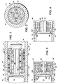
- Figure 1 of the drawings illustrates the first, and least complex, embodiment of the invention.
- the primary components of the first embodiment comprise a heated barrel or stator 10 having a cylindrical bore surface 12 which defines a cylindrical chamber 14 having a longitudinal axis coextensive with the center of cylindrical surface 12.
- a conventional power driven extruder screw 16 is coaxially positioned with respect to cylindrical bore 12 in chamber 14 and is rotated about its axis in conventional well known manner by power drive means (not shown).
- the extruder screw 16 can, for example, be of the types shown in U.S. Patent Nos. 4,779,989, 5,158,784 or 5,013,233.
- the invention is not limited to the foregoing types of extruder screws and a large number of conventional extruder screws and drive arrangements for same could be employed in practice of the invention.
- the extruder screw is capable of being moved to the right in the downstream direction for effecting injection of the polymer melt with such movement being effected by conventional piston means such as shown in Figure 2 of U.S. Patent No. 5, 013, 233
- rotation of the power driven extruder screw 16 effects the flow of polymer melt in the direction of arrows 18 from left to right through annular infeed opening 19 as shown in Figure 1.
- the left to right flow of the polymer melt is in a downstream direction and the term "downstream" means to the right and the term “upstream” means to the left as shown in Figure 1.
- the extruder screw includes an outwardly extending spiral screw member such as that shown in U.S. Patent No. 5, 013, 233 but which is not illustrated in the drawings for the sake of clarity.
- a driven shaft extension 20 extends in the down stream direction from the downstream end of the power driven extruder screw 16 and includes a key slot 22 in which a drive key 24 is positioned. The outer portion of drive key 24 is positioned in a slot in a rotor sleeve 26 so as to effect rotation of rotor sleeve 26.
- a plurality of driven rotor rings 28 extend radially outward from rotor sleeve 26 in a unitary manner as shown in Figure 1. Each driven rotor ring 28 has an outer cylindrical surface spaced from cylindrical bore surface 12 of barrel 10 and an upstream face 32 and a downstream face 34. Thus, rotation of rotor sleeve 26 easily effects driven rotation of the driven rotor rings 28 in an obvious manner without any frictional drag from barrel 10.
- a plurality of floating rings 36 are also provided on rotor sleeve 26 with the floating rings 36 being interleaved with the driven rotor rings 28.
- the floating rings 36 are not driven by rotor sleeve 26 but are instead mounted so as to be capable of rotation relative to rotor sleeve 26.
- Each floating ring 36 has an upstream face 38 which faces the downstream face 34 of an adjacent driven rotor ring 28.
- each floating ring has a downstream face 40 which faces an upstream face 32 of the next adjacent driven rotor ring 28 as shown in Figure 1.
- each floating ring 36 has an outer cylindrical surface 42 defining its outer periphery and lightly engaging the inner cylindrical surface 12 of the barrel or stator 10.
- Each of the driven rotor rings 28 is provided with a plurality of polymer flow passageways 44 which extend between their upstream face 32 and their downstream face 34 as shown in Figure 1.
- the polymer flow passageways 44 are arranged in three concentric circles comprising an inner circle most closely adjacent to rotor sleeve 26, an intermediate circle adjacent the inner circle and an outermost circle adjacent the outer periphery of each driven rotor ring as shown in Figure 2.
- the floating rings 36 are similarly provided with polymer flow passageways 46 which can be precisely aligned with the passageways 44 of the driven rotor rings 28. However, it should be understood that relative rotation of floating rings 36 with respect to driven rotor rings 28 causes such total alignment of the polymer flow apertures to be momentary.
- the power driven extruder screw 16, driven shaft 20, drive key 24 and rotor sleeve 26 are rotated by conventional electric motor drive means and such rotation consequently results in rotation of the driven rotor rings 28 in an obvious manner.
- Rotation of the power driven extruder screw 16 causes polymer melt to flow in the direction of arrows 18 and into the space immediately upstream of the power driven rotor ring 28 facing the screw 16 as shown in Figure 1.
- the polymer melt flows into the polymer flow passageways 44 of the most upstream power driven rotor ring 28 and moves through polymer passageway 44 to enter into the polymer flow passageway 46 of the floating ring 36 immediately downstream of the most upstream driven rotor ring 28.
- the frictional engagement of the outer cylindrical surface 42 of the floating rings 36 causes some resistance to rotation of the floating rings so that the power driven rotor rings 28 consequently rotate at a greater velocity than the floating rings 36.
- the speed of the polymer melt is quite substantial so that the polymer melt creates rotational force on floating rings 36 sufficient to overcome the,friction between surfaces 12 and 30 and causes the floating rings to rotate.
- the frictional drag between outer surface 30 of the floating rings and the barrel inner surface 12 causes floating rings 36 to rotate at a slower speed than the speed of rotation of the driven rotor rings 28.
- a second embodiment of the invention illustrated in Figures 3 and 4 differs from the first embodiment in that the initial movement of the power driven extruder screw 16 from its fully retracted position toward the downstream end of the barrel serves to effect closure of the annular infeed opening 19 between the extruder screw and the mixing chamber to preclude reverse flowback of polymer melt into the extruder screw.
- the foregoing results are achieved by the employment of a modified floating ring 136 positioned in facing relation to a conical valve surface 152 on the downstream end of power driven extruder screw 16 instead of a driven ring as employed in the embodiment of Figures 1 and 2.
- the upstream or forward face of the modified floating ring 136 includes a conical ring valve surface 150 which faces the conical through valve surface 152 as shown in Figure 3.
- the modified floating ring 136 includes a plurality of inner ring polymer flow passageways 146 which communicate with the next adjacent downstream ring polymer flow passageways 44 of driven rotor ring 128 which is identical to the driven rotor ring 28 of the first embodiment
- the modified floating ring 136 also includes a plurality of canted polymer flow passageways 148 which communicate with the outer most ring polymer flow passageways 144 of the driven ring member 128. It should also be observed that the modified floating ring 136 also has a group of intermediately positioned polymer flow passageways aligned with the intermediate group of polymer flow passageways of the next adjacent ring but which is not illustrated in the drawings.
- valve components are positioned so that the valve surfaces 150 and 152 are spaced from each other as shown in Figure 3.
- the aforementioned positioning of the valve components provides for the open annular infeed passageway 154 of annular shape between the valve surfaces which permits the inflow of polymer melt in the manner shown by the arrows in Figure 3.
- valve surfaces 150 and 152 are forcefully engaged with each other to close annular inflow passageway 154 to prevent reverse flow of polymer melt back toward the auger during the high pressure injection operation.
- the flow of polymer melt through the polymer flow passageways 44 enters the passageways of the floating rings 36 to effect rotational drive to the floating ring 36 due to the fact that the driven rings are rotating faster than the floating rings
- the polymer melt is consequently subjected to a shearing action due to the speed differential between the two different types of rings and the mixing of the polymer melt is consequently enhanced.
- the speed of rotation differential between the floating ring and the driven ring will be less than it will be if the viscosity was of a reduced value
- discharge of the polymer melt through the passageways on the downstream side of the floating rings enters a driven rotor ring that is rotating at a greater velocity than the speed of rotation of the floating ring s ) that shearing mixing of the polymer melt is effected at each transfer point from the float ng rings to the driven rings.
Landscapes
- Engineering & Computer Science (AREA)
- Mechanical Engineering (AREA)
- Manufacturing & Machinery (AREA)
- Processing And Handling Of Plastics And Other Materials For Molding In General (AREA)
Applications Claiming Priority (2)
| Application Number | Priority Date | Filing Date | Title |
|---|---|---|---|
| US09/189,946 US6254266B1 (en) | 1998-05-22 | 1998-11-12 | Floating ring mixer for extruder |
| US189946 | 2002-07-03 |
Publications (1)
| Publication Number | Publication Date |
|---|---|
| EP1000656A1 true EP1000656A1 (de) | 2000-05-17 |
Family
ID=22699417
Family Applications (1)
| Application Number | Title | Priority Date | Filing Date |
|---|---|---|---|
| EP99307428A Withdrawn EP1000656A1 (de) | 1998-11-12 | 1999-09-20 | Mischer für einen Extruder mit schwimmenden Ringen |
Country Status (4)
| Country | Link |
|---|---|
| US (1) | US6254266B1 (de) |
| EP (1) | EP1000656A1 (de) |
| CA (1) | CA2288542A1 (de) |
| MX (1) | MXPA99010441A (de) |
Cited By (2)
| Publication number | Priority date | Publication date | Assignee | Title |
|---|---|---|---|---|
| WO2004035282A2 (en) | 2002-10-21 | 2004-04-29 | Basf Aktiengesellschaft | Mixing device |
| CN110809938A (zh) * | 2019-11-18 | 2020-02-21 | 湖南省中医药研究院 | 黄精种子快速萌发的装置及方法 |
Families Citing this family (7)
| Publication number | Priority date | Publication date | Assignee | Title |
|---|---|---|---|---|
| DE10217758B4 (de) * | 2002-04-20 | 2005-06-16 | Krauss-Maffei Kunststofftechnik Gmbh | Rückstromsperre für Spritzgießmaschine |
| US6709147B1 (en) | 2002-12-05 | 2004-03-23 | Rauwendaal Extrusion Engineering, Inc. | Intermeshing element mixer |
| US7246936B2 (en) * | 2004-06-04 | 2007-07-24 | Certainteed Corp. | Dynamic mixer screw tip |
| DE102006014692B3 (de) * | 2006-03-28 | 2007-08-02 | Berstorff Gmbh | Schneckenelement |
| US10406722B2 (en) | 2016-09-22 | 2019-09-10 | Jeffrey A. Myers | Independently driven device for use with plastic melt feed screw |
| CN112265249B (zh) * | 2020-09-30 | 2022-09-13 | 佛山科学技术学院 | 基于挤压拉伸的高分子塑化输运方法、模块、装置及设备 |
| AT526874B1 (de) * | 2023-01-26 | 2025-01-15 | Ach Solution Gmbh | Materialfördervorrichtung |
Citations (5)
| Publication number | Priority date | Publication date | Assignee | Title |
|---|---|---|---|---|
| GB1475216A (en) * | 1974-10-09 | 1977-06-01 | Barmag Barmer Maschf | Mixing machine |
| US4057379A (en) * | 1974-06-04 | 1977-11-08 | Sato Iron Works Co., Ltd. | Kneading and extruding apparatus for extrudable material |
| US4541982A (en) * | 1982-12-06 | 1985-09-17 | Windmoller & Holscher | Process and apparatus for forming and rearranging partial streams of molten materials processed in an extruder for making thermoplastic and/or elastomeric products |
| US5013233A (en) * | 1988-05-03 | 1991-05-07 | Universiteit Twente | Distributive mixer device |
| JPH10100223A (ja) * | 1996-09-30 | 1998-04-21 | Sekisui Chem Co Ltd | 管状体の製造方法及び管状体製造用金型 |
Family Cites Families (8)
| Publication number | Priority date | Publication date | Assignee | Title |
|---|---|---|---|---|
| US3239882A (en) * | 1962-07-18 | 1966-03-15 | Sterling Extruder Corp | Dispersion head for extruder |
| GB1318503A (en) * | 1970-07-07 | 1973-05-31 | Desma Werke Gmbh | Conveying worm injection-moulding machine reverse-flow preventers |
| US3942773A (en) * | 1972-07-19 | 1976-03-09 | Csongor Desider G | Method and apparatus for extruding melted plastic mixtures |
| US4408887A (en) * | 1981-12-07 | 1983-10-11 | Kishihiro Yamaoka | Continuous kneader |
| US4779989A (en) * | 1986-12-01 | 1988-10-25 | Barr Robert A | Transfer mixer assembly for use with an extruder screw of a polymer extruder or the like |
| DE4202821C2 (de) * | 1992-01-31 | 1995-01-26 | S Rockstedt Gmbh Maschf | Mehrwellige kontinuierlich arbeitende Misch- und Knetmaschine für plastifizierbare Massen |
| US5599096A (en) * | 1996-03-04 | 1997-02-04 | Rog; Aleksandr | Disc screw extruder with free-floating operating member |
| US5988866A (en) * | 1998-05-22 | 1999-11-23 | Barr; Robert A. | Floating sleeve mixer and method |
-
1998
- 1998-11-12 US US09/189,946 patent/US6254266B1/en not_active Expired - Lifetime
-
1999
- 1999-09-20 EP EP99307428A patent/EP1000656A1/de not_active Withdrawn
- 1999-11-04 CA CA002288542A patent/CA2288542A1/en not_active Abandoned
- 1999-11-12 MX MXPA99010441A patent/MXPA99010441A/es unknown
Patent Citations (5)
| Publication number | Priority date | Publication date | Assignee | Title |
|---|---|---|---|---|
| US4057379A (en) * | 1974-06-04 | 1977-11-08 | Sato Iron Works Co., Ltd. | Kneading and extruding apparatus for extrudable material |
| GB1475216A (en) * | 1974-10-09 | 1977-06-01 | Barmag Barmer Maschf | Mixing machine |
| US4541982A (en) * | 1982-12-06 | 1985-09-17 | Windmoller & Holscher | Process and apparatus for forming and rearranging partial streams of molten materials processed in an extruder for making thermoplastic and/or elastomeric products |
| US5013233A (en) * | 1988-05-03 | 1991-05-07 | Universiteit Twente | Distributive mixer device |
| JPH10100223A (ja) * | 1996-09-30 | 1998-04-21 | Sekisui Chem Co Ltd | 管状体の製造方法及び管状体製造用金型 |
Non-Patent Citations (1)
| Title |
|---|
| PATENT ABSTRACTS OF JAPAN vol. 1998, no. 09 31 July 1998 (1998-07-31) * |
Cited By (3)
| Publication number | Priority date | Publication date | Assignee | Title |
|---|---|---|---|---|
| WO2004035282A2 (en) | 2002-10-21 | 2004-04-29 | Basf Aktiengesellschaft | Mixing device |
| US7255472B2 (en) | 2002-10-21 | 2007-08-14 | Basf Aktiengesellschaft | Mixing device with mixing ring having offset channels with spaced baffles |
| CN110809938A (zh) * | 2019-11-18 | 2020-02-21 | 湖南省中医药研究院 | 黄精种子快速萌发的装置及方法 |
Also Published As
| Publication number | Publication date |
|---|---|
| US6254266B1 (en) | 2001-07-03 |
| MXPA99010441A (es) | 2005-04-01 |
| CA2288542A1 (en) | 2000-05-12 |
Similar Documents
| Publication | Publication Date | Title |
|---|---|---|
| US6709147B1 (en) | Intermeshing element mixer | |
| US3564650A (en) | Apparatus for extruding plastic strands and cutting them up into pellets | |
| CA2462438C (en) | Apparatus for injection molding multilayered articles | |
| EP1156918B1 (de) | Schneckenextruder mit verbesserten dispersiven mischelementen | |
| US5215374A (en) | Plasticizing sections of cold feed rubber extruders | |
| US6254266B1 (en) | Floating ring mixer for extruder | |
| US5413475A (en) | Serial two-stage extruder | |
| US3790328A (en) | Apparatus for feeding elastic melt extruders | |
| US20020163852A1 (en) | Four wing, non-intermeshing rotors for synchronous drive to provide improved dispersive and distributive mixing in internal batch mixers | |
| US4306848A (en) | Injection molding apparatus having low shear screw | |
| US3613160A (en) | Variable bypass orifice for continuous mixer | |
| US5988866A (en) | Floating sleeve mixer and method | |
| US5304054A (en) | Plasticizing sections of cold feed rubber extruders | |
| US3209408A (en) | Antifriction plasticizer head for plastic-extruding machines | |
| CN108582723B (zh) | 复合锥形螺盘挤出装置 | |
| US7255472B2 (en) | Mixing device with mixing ring having offset channels with spaced baffles | |
| US4714422A (en) | Rotary plasticator screw injection machine | |
| US20180079126A1 (en) | Independently driven device for use with plastic melt feed screw | |
| US3271820A (en) | Pelletizer with steam ejection of pellets | |
| US6286988B1 (en) | Extrusion head having toothed wheels with mixing device and adjustable shear effect | |
| US3360821A (en) | Elastic melt extruder with peripheral feed | |
| US6062717A (en) | Chopper mixing screw | |
| US4015916A (en) | Heating and stratification device for an injection molding machine | |
| US10406722B2 (en) | Independently driven device for use with plastic melt feed screw | |
| CN116872468B (zh) | 塑料件加工用塑料挤出设备 |
Legal Events
| Date | Code | Title | Description |
|---|---|---|---|
| PUAI | Public reference made under article 153(3) epc to a published international application that has entered the european phase |
Free format text: ORIGINAL CODE: 0009012 |
|
| AK | Designated contracting states |
Kind code of ref document: A1 Designated state(s): DE FR GB IT |
|
| AX | Request for extension of the european patent |
Free format text: AL;LT;LV;MK;RO;SI |
|
| 17P | Request for examination filed |
Effective date: 20001117 |
|
| AKX | Designation fees paid |
Free format text: DE FR GB IT |
|
| RAP1 | Party data changed (applicant data changed or rights of an application transferred) |
Owner name: MYERS, JEFFREY, A. Owner name: BARR, ROBERT |
|
| RIN1 | Information on inventor provided before grant (corrected) |
Inventor name: MYERS, JEFFREY, A. Inventor name: BARR, ROBERT |
|
| 17Q | First examination report despatched |
Effective date: 20030404 |
|
| GRAP | Despatch of communication of intention to grant a patent |
Free format text: ORIGINAL CODE: EPIDOSNIGR1 |
|
| STAA | Information on the status of an ep patent application or granted ep patent |
Free format text: STATUS: THE APPLICATION IS DEEMED TO BE WITHDRAWN |
|
| 18D | Application deemed to be withdrawn |
Effective date: 20040803 |