EP1000663A1 - Vorrichtung zum Abscheiden von magnetisierbaren Teilen aus schütt- oder fliessfähigem Gut - Google Patents
Vorrichtung zum Abscheiden von magnetisierbaren Teilen aus schütt- oder fliessfähigem Gut Download PDFInfo
- Publication number
- EP1000663A1 EP1000663A1 EP99121457A EP99121457A EP1000663A1 EP 1000663 A1 EP1000663 A1 EP 1000663A1 EP 99121457 A EP99121457 A EP 99121457A EP 99121457 A EP99121457 A EP 99121457A EP 1000663 A1 EP1000663 A1 EP 1000663A1
- Authority
- EP
- European Patent Office
- Prior art keywords
- tube
- magnets
- rods
- magnetic
- outlet
- Prior art date
- Legal status (The legal status is an assumption and is not a legal conclusion. Google has not performed a legal analysis and makes no representation as to the accuracy of the status listed.)
- Granted
Links
- 239000000463 material Substances 0.000 title claims abstract description 9
- 230000009969 flowable effect Effects 0.000 title claims abstract description 4
- 239000002245 particle Substances 0.000 claims abstract description 23
- 238000000926 separation method Methods 0.000 claims 1
- 239000006249 magnetic particle Substances 0.000 abstract 2
- 239000002801 charged material Substances 0.000 abstract 1
- 239000013014 purified material Substances 0.000 abstract 1
- XEEYBQQBJWHFJM-UHFFFAOYSA-N Iron Chemical compound [Fe] XEEYBQQBJWHFJM-UHFFFAOYSA-N 0.000 description 16
- 229910052742 iron Inorganic materials 0.000 description 8
- 238000000034 method Methods 0.000 description 7
- 238000004140 cleaning Methods 0.000 description 6
- 238000005137 deposition process Methods 0.000 description 2
- 229910000831 Steel Inorganic materials 0.000 description 1
- 230000006735 deficit Effects 0.000 description 1
- 239000010959 steel Substances 0.000 description 1
- 239000002699 waste material Substances 0.000 description 1
Images

Classifications
-
- B—PERFORMING OPERATIONS; TRANSPORTING
- B03—SEPARATION OF SOLID MATERIALS USING LIQUIDS OR USING PNEUMATIC TABLES OR JIGS; MAGNETIC OR ELECTROSTATIC SEPARATION OF SOLID MATERIALS FROM SOLID MATERIALS OR FLUIDS; SEPARATION BY HIGH-VOLTAGE ELECTRIC FIELDS
- B03C—MAGNETIC OR ELECTROSTATIC SEPARATION OF SOLID MATERIALS FROM SOLID MATERIALS OR FLUIDS; SEPARATION BY HIGH-VOLTAGE ELECTRIC FIELDS
- B03C1/00—Magnetic separation
- B03C1/02—Magnetic separation acting directly on the substance being separated
- B03C1/10—Magnetic separation acting directly on the substance being separated with cylindrical material carriers
- B03C1/12—Magnetic separation acting directly on the substance being separated with cylindrical material carriers with magnets moving during operation; with movable pole pieces
Definitions
- the invention relates to a device for separating magnetizable Parts made of pourable or flowable goods.
- the said good can be in any form, as is the case with industrial or other applications.
- magnetizable parts iron filings or any other material that can be used are magnetic or can be magnetized.
- a known device of this type comprises a chute, which in its upper area has an inlet for the material to be cleaned, and in an outlet for the cleaned, i.e. of magnetizable particles free goods, as well as an outlet for the magnetizable particles.
- a chute which in its upper area has an inlet for the material to be cleaned, and in an outlet for the cleaned, i.e. of magnetizable particles free goods, as well as an outlet for the magnetizable particles.
- the tubes each contain a magnetic rod.
- the goods are fed into the shaft above. It fails through the grids.
- the magnetizable particles are thereby Magnetic force held on the outer surface of each tube, so that good free of magnetizable particles falls further down and optionally through another grate where another Cleaning takes place.
- the outer surface of the pipes After a certain period of time, the outer surface of the pipes a layer of magnetizable particles is formed. Then they will Magnetic rods with the help of a common bracket in the axial direction pulled out the pipes. With this axial movement of the magnetic bars also migrate those deposited on the lateral surface of the pipe in question Particles in the same direction, i.e. to the one end of that Tube where they drop due to a lack of magnetic force.
- the method has the following disadvantage: the removal of the above magnetizable particles sitting on the tubes is a discontinuous one Process. During this process, the pipes in question fall for the Deposition process. You can now all pipes during a free from magnetizable particles for a certain period of time. This means, that the entire cleaning process is interrupted for this period. Part of the pipes can also be freed of magnetizable particles, and run the cleaning process on the remaining number of pipes. This means that the cleaning process only with reduced throughput can be carried out. Both types of cleaning are disadvantageous.
- the invention has for its object a device of the type mentioned to be designed in such a way that the removal of magnetizable particles have deposited on the outer surfaces of the pipes without Impairment of the cleaning process can be carried out.
- the inventor has followed a very elegant path.
- By turning the Magnetic rods with helically arranged magnets inside the fixed pipe finds a continuous discharge of magnetizable particles on the outer surface of the tube instead.
- the particles namely migrate according to the circulation of the helically arranged Magnets along the outer surface of the pipe in question and fall on End of the pipe into a separate shaft for iron particles. in the The area of this shaft is non-magnetic
- the deposition process is thus done by removing the magnetizable Particles in no way affected.
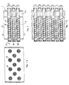
- Figures 1a and 1b show one in a vertical section and in a plan view Device according to the invention in a schematic representation.
- Figure 2 shows a coil magnetic rod in an elevation view.
- FIG. 3 is an enlarged detail representation from the subject of FIG Figure 2.
- Figure 4 is a view of the subject of Figure 2 looking towards a Face.
- the device shown schematically in FIGS. 1a and 1b comprises a device Drop shaft 1. This has three grids 2, 12, 22 arranged one above the other on. Each grate comprises several tubes 3. Each tube encloses one Coil magnetic rod 4.
- Each tube 3 and the associated coil magnetic rod 4 are mutually arranged coaxially.
- the tubes 3 are fixed, and the Coil magnetic bars continuously turn around during operation their own longitudinal axis.
- the helical magnetic rods can be seen more clearly from FIGS. 2, 3 and 4.
- each coil magnetic rod comprises a shaft 4.1.
- the shaft 4.1 carries a continuous helix 4.2. She also wears one Variety of magnets 4.3. The magnets are between each Gears of the helix 4.2 arranged.
- the wave 4.1 of everyone Helical magnetic rod 4 is driven at one end. The drive is not shown here.
- each coil magnetic rod 4 is enclosed by a tube 3.
- the magnets generate magnetic fields. Please refer the symbols + and -.
- the shaft 4.1 is made of steel St37.
- the good to be treated is a product of Sugar industry. It is a powdery good and contains iron particles. This good is shown in FIG. 1 at the chute 1 at the top located inlet 1.1 supplied. It falls through the grids 2, 12, 22 and occurs in a largely purified form, i.e. without the iron particles, on Outlet 1.2 out.
- the bars comprise each the fixed tube 3 and the inner one Coil magnetic rod 4.
- the iron particles are separated by the magnetic Fields held on the outer surface of the fixed tubes.
- the coil magnetic rod each comprising the shaft 4.1, the helix 4.2 and the magnet 4.3, rotating about its own axis, move the iron particles in the axial direction of each tube to the iron particle waste chute (1.3) where they drop due to the lack of a magnetic field.
- the iron particle waste chute In the area of the iron particle chute is non-magnetic.
Landscapes
- Physical Or Chemical Processes And Apparatus (AREA)
- Investigating Or Analyzing Materials By The Use Of Magnetic Means (AREA)
Abstract
Description
Claims (3)
- Vorrichtung zum kontinuierlichen Abscheiden von magnetisierbaren Teilchen aus schütt- oder fließfähigem Gut;1.1 mit einer Kammer, die einen Einlaß (1.1) für das teilchenbeladene Gut, einen Auslaß (1.2) für das gereinigte Gut und einen Auslaß (1.3) für die magnetisierbaren Teilchen aufweist;1.2 mit einer Anzahl von Stabrosten (2, 12, 22), die im Strömungsweg des Gutes angeordnet sind;1.3 die Stäbe umfassen jeweils ein Rohr (3) sowie einen von diesem umschlossenen Wendelmagnetstab(4) mit Magneten (4.3);1.4 die Magnete (4.3) sind wendelartig zur Rohrachse angeordnet;1.5 die Wendelmagnetstäbe sind jeweils durch einen Antrieb um die Längsachse des Rohres (3) verdrehbar.
- Vorrichtung nach Anspruch 1, dadurch gekennzeichnet, daß die Magnete (4.3) von einer zur Rohrachse koaxialen Welle (4.1) getragen sind.
- Vorrichtung nach einem der Ansprüche 1 bis 3, dadurch gekennzeichnet, daß die Rohre (3) feststehen.
Applications Claiming Priority (2)
| Application Number | Priority Date | Filing Date | Title |
|---|---|---|---|
| DE19852142 | 1998-11-12 | ||
| DE19852142A DE19852142C2 (de) | 1998-11-12 | 1998-11-12 | Vorrichtung zum Abscheiden von magnetisierbaren Teilen aus schütt- oder fließfähigem Gut |
Publications (2)
| Publication Number | Publication Date |
|---|---|
| EP1000663A1 true EP1000663A1 (de) | 2000-05-17 |
| EP1000663B1 EP1000663B1 (de) | 2004-03-17 |
Family
ID=7887527
Family Applications (1)
| Application Number | Title | Priority Date | Filing Date |
|---|---|---|---|
| EP99121457A Expired - Lifetime EP1000663B1 (de) | 1998-11-12 | 1999-10-28 | Vorrichtung zum Abscheiden von magnetisierbaren Teilen aus schütt- oder fliessfähigem Gut |
Country Status (2)
| Country | Link |
|---|---|
| EP (1) | EP1000663B1 (de) |
| DE (2) | DE19852142C2 (de) |
Cited By (9)
| Publication number | Priority date | Publication date | Assignee | Title |
|---|---|---|---|---|
| WO2002034653A1 (en) * | 2000-10-26 | 2002-05-02 | Shell Internationale Research Maatschappij B.V. | Device for transporting particles of magnetic material |
| EP1379334A4 (de) * | 2001-02-21 | 2008-07-02 | Robert T Wysolmierski | Magnetische eisenteilchenentfernungs- und sammelvorrichtung |
| US7419014B2 (en) | 2003-10-29 | 2008-09-02 | Shell Oil Company | Fluid jet drilling tool |
| US7448151B2 (en) | 2003-07-09 | 2008-11-11 | Shell Oil Company | Tool for excavating an object |
| WO2010031617A1 (de) * | 2008-09-18 | 2010-03-25 | Siemens Aktiengesellschaft | Vorrichtung zum trennen ferromagnetischer partikel aus einer suspension |
| CN102294299A (zh) * | 2010-06-25 | 2011-12-28 | 三隆齿轮股份有限公司 | 污油中磁性碎屑处理装置 |
| WO2014161819A1 (de) * | 2013-04-02 | 2014-10-09 | Dürr Systems GmbH | Vorrichtung und verfahren zum abscheiden von magnetisierbaren partikeln aus einem fluid |
| ITUA20163952A1 (it) * | 2016-05-11 | 2017-11-11 | Lorenzo Musa | Macchina elettromagnetica per selezionare le sementi |
| CN116899745A (zh) * | 2023-07-25 | 2023-10-20 | 浙江南都电源动力股份有限公司 | 一种管道自动清洁除铁器及除铁装置 |
Families Citing this family (4)
| Publication number | Priority date | Publication date | Assignee | Title |
|---|---|---|---|---|
| DE102015010967A1 (de) | 2014-09-12 | 2016-03-17 | Carl Freudenberg Kg | Filterelement zur Reinigung eines Luftstroms |
| CN106581850A (zh) * | 2016-12-08 | 2017-04-26 | 重庆大学 | 复杂孔隙结构中磁性颗粒的运动调控及回收方法 |
| CN109351469A (zh) * | 2018-11-14 | 2019-02-19 | 王光领 | 一种新型磁性过滤筛 |
| CN120079516B (zh) * | 2025-04-16 | 2026-04-03 | 江苏楚金新材料科技有限公司 | 一种基于废旧锂电池回收的高纯度铜粉的装置 |
Citations (3)
| Publication number | Priority date | Publication date | Assignee | Title |
|---|---|---|---|---|
| US2913113A (en) * | 1957-08-30 | 1959-11-17 | Los Angeles By Products Co | Method and apparatus for salvaging metal articles |
| DE2438972A1 (de) * | 1974-03-22 | 1975-09-25 | Bunri Ind Co Ltd | Foerderer fuer magnetische stoffe |
| US4867869A (en) * | 1987-12-03 | 1989-09-19 | Venturedyne, Ltd. | Grate magnet |
Family Cites Families (1)
| Publication number | Priority date | Publication date | Assignee | Title |
|---|---|---|---|---|
| DE4124990A1 (de) * | 1991-07-27 | 1993-01-28 | Voith Gmbh J M | Magnetfeld-trenneinrichtung zum abschneiden ferromagnetischer metallteile aus suspensionen, insbesondere aus bei der wiederverarbeitung von altpapier anfallenden suspensionen |
-
1998
- 1998-11-12 DE DE19852142A patent/DE19852142C2/de not_active Expired - Fee Related
-
1999
- 1999-10-28 DE DE59908864T patent/DE59908864D1/de not_active Expired - Fee Related
- 1999-10-28 EP EP99121457A patent/EP1000663B1/de not_active Expired - Lifetime
Patent Citations (3)
| Publication number | Priority date | Publication date | Assignee | Title |
|---|---|---|---|---|
| US2913113A (en) * | 1957-08-30 | 1959-11-17 | Los Angeles By Products Co | Method and apparatus for salvaging metal articles |
| DE2438972A1 (de) * | 1974-03-22 | 1975-09-25 | Bunri Ind Co Ltd | Foerderer fuer magnetische stoffe |
| US4867869A (en) * | 1987-12-03 | 1989-09-19 | Venturedyne, Ltd. | Grate magnet |
Cited By (12)
| Publication number | Priority date | Publication date | Assignee | Title |
|---|---|---|---|---|
| WO2002034653A1 (en) * | 2000-10-26 | 2002-05-02 | Shell Internationale Research Maatschappij B.V. | Device for transporting particles of magnetic material |
| AU2002221791B2 (en) * | 2000-10-26 | 2004-04-22 | Shell Internationale Research Maatschappij B.V. | Device for transporting particles of magnetic material |
| EP1379334A4 (de) * | 2001-02-21 | 2008-07-02 | Robert T Wysolmierski | Magnetische eisenteilchenentfernungs- und sammelvorrichtung |
| US7448151B2 (en) | 2003-07-09 | 2008-11-11 | Shell Oil Company | Tool for excavating an object |
| US7419014B2 (en) | 2003-10-29 | 2008-09-02 | Shell Oil Company | Fluid jet drilling tool |
| WO2010031617A1 (de) * | 2008-09-18 | 2010-03-25 | Siemens Aktiengesellschaft | Vorrichtung zum trennen ferromagnetischer partikel aus einer suspension |
| US8840794B2 (en) | 2008-09-18 | 2014-09-23 | Siemens Aktiengesellschaft | Device for separating ferromagnetic particles from a suspension |
| CN102294299A (zh) * | 2010-06-25 | 2011-12-28 | 三隆齿轮股份有限公司 | 污油中磁性碎屑处理装置 |
| WO2014161819A1 (de) * | 2013-04-02 | 2014-10-09 | Dürr Systems GmbH | Vorrichtung und verfahren zum abscheiden von magnetisierbaren partikeln aus einem fluid |
| CN105188945A (zh) * | 2013-04-02 | 2015-12-23 | 杜尔系统有限公司 | 用于将能磁化的颗粒从流体中分离出来的设备和方法 |
| ITUA20163952A1 (it) * | 2016-05-11 | 2017-11-11 | Lorenzo Musa | Macchina elettromagnetica per selezionare le sementi |
| CN116899745A (zh) * | 2023-07-25 | 2023-10-20 | 浙江南都电源动力股份有限公司 | 一种管道自动清洁除铁器及除铁装置 |
Also Published As
| Publication number | Publication date |
|---|---|
| DE19852142C2 (de) | 2001-08-16 |
| DE59908864D1 (de) | 2004-04-22 |
| EP1000663B1 (de) | 2004-03-17 |
| DE19852142A1 (de) | 2000-05-25 |
Similar Documents
| Publication | Publication Date | Title |
|---|---|---|
| EP1000663B1 (de) | Vorrichtung zum Abscheiden von magnetisierbaren Teilen aus schütt- oder fliessfähigem Gut | |
| EP2812119B1 (de) | Verfahren und vorrichtung zur trennung nichtmagnetischer bestandteile aus einem gemenge von metallschrott | |
| EP2981363B1 (de) | Vorrichtung und verfahren zum abscheiden von magnetisierbaren partikeln aus einem fluid | |
| DE2551030A1 (de) | Abwasser-reinigungsverfahren und vorrichtung zur durchfuehrung des verfahrens | |
| DE69017401T2 (de) | Magnetische Nassabscheider mit hoher Intensität. | |
| DE102010036267A1 (de) | Trennverfahren und -vorrichtung für NE-Metalle | |
| DE3707938A1 (de) | Vorrichtung zur aufbereitung, insbesondere filtrierung, der raumluft | |
| DE202019100675U1 (de) | Hocheffiziente Abwasserreinigungsvorrichtung | |
| DE2555798C3 (de) | Vorrichtung zum Abtrennen von stark magnetischen Teilchen | |
| CH627682A5 (de) | Vorrichtung zur bearbeitung von blechen mittels magnetpulver. | |
| DE69216813T2 (de) | Filtrationsanlage für Luftbehandlungsysteme oder Küchenhauben | |
| DE2210029A1 (de) | Verfahren und Vorrichtung zum magneti sehen Abscheiden von festen, magnetischen Teilchen aus einem stromenden Fluid | |
| DE2749661C2 (de) | Magnetscheider | |
| DE3218791A1 (de) | Magnetabscheider fuer rieselfaehiges festes gut | |
| DE102006013256B4 (de) | Vorrichtung und Verfahren zum Entfernen von Partikeln aus einer Flüssigkeit | |
| DE534622C (de) | Verfahren und Vorrichtung zur Trennung magnetisierbarer Bestandteile aus staubfoermigem Gut | |
| EP0501033A1 (de) | Filter zur Abscheidung ferromagnetischer und/oder paramagnetischer Verunreinigungen aus dünnflüssigen Medien | |
| DE2458577C3 (de) | Verfahren zum Reinigen von ölhaltigem Abwasser | |
| DE102011102215A1 (de) | Verfahren und Vorrichtung zur Absonderung aller nichtmagnetischen Bestandteile aus einem Gemenge von Metallschrott zur Erzielung reinen Eisenschrotts. | |
| DE1106712B (de) | Magnetisch oder elektrostatisch-magnetisch wirkende Vorrichtung zur Abscheidung magnetisierbarer Teile | |
| DE1963700C3 (de) | Verfahren und Vorrichtung zum Abscheiden von Sinter aus Brauch- oder Abwasser von Hüttenwerken | |
| EP3483126A1 (de) | Kläranlage sowie verfahren zur behandlung von abwasser | |
| DE1221390B (de) | Verfahren zum Reinigen von Magnetfiltern | |
| DE1300882B (de) | Magnetmechanische Vorrichtung zum Abscheiden und/oder zum Transport von magnetisierbaren Stoffen | |
| EP2324927A1 (de) | Einrichtung zum Aussortieren von magnetisch beeinflussbaren Stückchen |
Legal Events
| Date | Code | Title | Description |
|---|---|---|---|
| PUAI | Public reference made under article 153(3) epc to a published international application that has entered the european phase |
Free format text: ORIGINAL CODE: 0009012 |
|
| 17P | Request for examination filed |
Effective date: 20000311 |
|
| AK | Designated contracting states |
Kind code of ref document: A1 Designated state(s): DE GB IT NL |
|
| AX | Request for extension of the european patent |
Free format text: AL;LT;LV;MK;RO;SI |
|
| RAP1 | Party data changed (applicant data changed or rights of an application transferred) |
Owner name: ALLGAIER-WERKE GMBH |
|
| AKX | Designation fees paid |
Free format text: DE GB IT NL |
|
| 17Q | First examination report despatched |
Effective date: 20030425 |
|
| GRAP | Despatch of communication of intention to grant a patent |
Free format text: ORIGINAL CODE: EPIDOSNIGR1 |
|
| GRAS | Grant fee paid |
Free format text: ORIGINAL CODE: EPIDOSNIGR3 |
|
| GRAA | (expected) grant |
Free format text: ORIGINAL CODE: 0009210 |
|
| AK | Designated contracting states |
Kind code of ref document: B1 Designated state(s): DE GB IT NL |
|
| REG | Reference to a national code |
Ref country code: GB Ref legal event code: FG4D Free format text: NOT ENGLISH |
|
| GBT | Gb: translation of ep patent filed (gb section 77(6)(a)/1977) |
Effective date: 20040317 |
|
| REF | Corresponds to: |
Ref document number: 59908864 Country of ref document: DE Date of ref document: 20040422 Kind code of ref document: P |
|
| PLBE | No opposition filed within time limit |
Free format text: ORIGINAL CODE: 0009261 |
|
| STAA | Information on the status of an ep patent application or granted ep patent |
Free format text: STATUS: NO OPPOSITION FILED WITHIN TIME LIMIT |
|
| 26N | No opposition filed |
Effective date: 20041220 |
|
| PGFP | Annual fee paid to national office [announced via postgrant information from national office to epo] |
Ref country code: GB Payment date: 20050923 Year of fee payment: 7 |
|
| PGFP | Annual fee paid to national office [announced via postgrant information from national office to epo] |
Ref country code: NL Payment date: 20051025 Year of fee payment: 7 |
|
| PGFP | Annual fee paid to national office [announced via postgrant information from national office to epo] |
Ref country code: DE Payment date: 20051130 Year of fee payment: 7 |
|
| PGFP | Annual fee paid to national office [announced via postgrant information from national office to epo] |
Ref country code: IT Payment date: 20061031 Year of fee payment: 8 |
|
| PG25 | Lapsed in a contracting state [announced via postgrant information from national office to epo] |
Ref country code: NL Free format text: LAPSE BECAUSE OF NON-PAYMENT OF DUE FEES Effective date: 20070501 Ref country code: DE Free format text: LAPSE BECAUSE OF NON-PAYMENT OF DUE FEES Effective date: 20070501 |
|
| GBPC | Gb: european patent ceased through non-payment of renewal fee |
Effective date: 20061028 |
|
| NLV4 | Nl: lapsed or anulled due to non-payment of the annual fee |
Effective date: 20070501 |
|
| PG25 | Lapsed in a contracting state [announced via postgrant information from national office to epo] |
Ref country code: GB Free format text: LAPSE BECAUSE OF NON-PAYMENT OF DUE FEES Effective date: 20061028 |
|
| PG25 | Lapsed in a contracting state [announced via postgrant information from national office to epo] |
Ref country code: IT Free format text: LAPSE BECAUSE OF NON-PAYMENT OF DUE FEES Effective date: 20071028 |