EP1000682A2 - Transport- und Positioniereinrichtung - Google Patents
Transport- und Positioniereinrichtung Download PDFInfo
- Publication number
- EP1000682A2 EP1000682A2 EP99121917A EP99121917A EP1000682A2 EP 1000682 A2 EP1000682 A2 EP 1000682A2 EP 99121917 A EP99121917 A EP 99121917A EP 99121917 A EP99121917 A EP 99121917A EP 1000682 A2 EP1000682 A2 EP 1000682A2
- Authority
- EP
- European Patent Office
- Prior art keywords
- drive
- swivel arm
- swivel
- handlebar
- guide
- Prior art date
- Legal status (The legal status is an assumption and is not a legal conclusion. Google has not performed a legal analysis and makes no representation as to the accuracy of the status listed.)
- Granted
Links
Images



Classifications
-
- B—PERFORMING OPERATIONS; TRANSPORTING
- B21—MECHANICAL METAL-WORKING WITHOUT ESSENTIALLY REMOVING MATERIAL; PUNCHING METAL
- B21D—WORKING OR PROCESSING OF SHEET METAL OR METAL TUBES, RODS OR PROFILES WITHOUT ESSENTIALLY REMOVING MATERIAL; PUNCHING METAL
- B21D43/00—Feeding, positioning or storing devices combined with, or arranged in, or specially adapted for use in connection with, apparatus for working or processing sheet metal, metal tubes or metal profiles; Associations therewith of cutting devices
- B21D43/02—Advancing work in relation to the stroke of the die or tool
- B21D43/04—Advancing work in relation to the stroke of the die or tool by means in mechanical engagement with the work
- B21D43/05—Advancing work in relation to the stroke of the die or tool by means in mechanical engagement with the work specially adapted for multi-stage presses
-
- B—PERFORMING OPERATIONS; TRANSPORTING
- B23—MACHINE TOOLS; METAL-WORKING NOT OTHERWISE PROVIDED FOR
- B23Q—DETAILS, COMPONENTS, OR ACCESSORIES FOR MACHINE TOOLS, e.g. ARRANGEMENTS FOR COPYING OR CONTROLLING; MACHINE TOOLS IN GENERAL CHARACTERISED BY THE CONSTRUCTION OF PARTICULAR DETAILS OR COMPONENTS; COMBINATIONS OR ASSOCIATIONS OF METAL-WORKING MACHINES, NOT DIRECTED TO A PARTICULAR RESULT
- B23Q1/00—Members which are comprised in the general build-up of a form of machine, particularly relatively large fixed members
- B23Q1/25—Movable or adjustable work or tool supports
- B23Q1/44—Movable or adjustable work or tool supports using particular mechanisms
- B23Q1/50—Movable or adjustable work or tool supports using particular mechanisms with rotating pairs only, the rotating pairs being the first two elements of the mechanism
- B23Q1/52—Movable or adjustable work or tool supports using particular mechanisms with rotating pairs only, the rotating pairs being the first two elements of the mechanism a single rotating pair
-
- B—PERFORMING OPERATIONS; TRANSPORTING
- B23—MACHINE TOOLS; METAL-WORKING NOT OTHERWISE PROVIDED FOR
- B23Q—DETAILS, COMPONENTS, OR ACCESSORIES FOR MACHINE TOOLS, e.g. ARRANGEMENTS FOR COPYING OR CONTROLLING; MACHINE TOOLS IN GENERAL CHARACTERISED BY THE CONSTRUCTION OF PARTICULAR DETAILS OR COMPONENTS; COMBINATIONS OR ASSOCIATIONS OF METAL-WORKING MACHINES, NOT DIRECTED TO A PARTICULAR RESULT
- B23Q7/00—Arrangements for handling work specially combined with or arranged in, or specially adapted for use in connection with, machine tools, e.g. for conveying, loading, positioning, discharging, sorting
- B23Q7/14—Arrangements for handling work specially combined with or arranged in, or specially adapted for use in connection with, machine tools, e.g. for conveying, loading, positioning, discharging, sorting co-ordinated in production lines
Definitions
- the invention relates to a transport and / or positioning device, especially for workpiece transfer, especially for the transport of sheet metal parts in transfer presses.
- Machining systems with several arranged in a row Processing stations require workpiece transport from workstation to workstation.
- the workpiece in question For example, a sheet metal part in a processing station record, lead out of this, it into the next Insert the processing station and release the workpiece there, in order to process it in one of parking position spaced from the processing station remain.
- large part presses where large body parts of motor vehicles, in individual cases Whole body side parts are processed, the parts are several meters wide. The is accordingly Relative distance between individual processing stations large.
- the sheet metal parts have a considerable weight on. These parts must have a high stroke rate
- the Transfer device the required drive power apply to the workpiece and at the same time a high one Must ensure positioning precision.
- Transfer systems for example the workpiece transport. between press stages are subject to also relatively narrow structural constraints. E.g. it is desirable that the square be on the side next to the press sliding tables remains free, so that Sliding tables unhindered by the transfer device be moved out of the side of the transfer press can.
- the object of the invention is therefore a To create a transport and / or positioning device, bridging relatively long transport routes in short Time and precise positioning of the transported Allows parts.
- the transport and / or positioning device has a lever gear with a swivel arm on one End carries a carrier that is in with the workpiece Be engaged or the workpiece otherwise can record.
- the swivel arm lies in the power transmission path, that goes from a power source to that Carrier extends.
- the swivel arm takes over a quick translation. He's on two of those Carrier means guided or driven at spaced locations, being the distance between these two digits is smaller than the distance of the carrier from the Swivel axis of the lever. This results in a leverage ratio. This leads to the fact that the carrier means a moves faster and more far-reaching than at drive means engaging the swivel arm. To these can Guides, e.g.
- linear guides, slides and the like belong. Because this has a lower maximum speed reach and travel shorter distances than that Carrier means, their mass plays for the dynamics of the drive not as important as the mass of the carrier. They can be designed to be precise Provide leadership. This can be a high positioning accuracy can be achieved. Through the Lever translation on the swivel arm makes it possible with good accuracy, long transport routes closed quickly run through.
- two are in relation to each other mirror-symmetrical drive devices provided, their swivel arms with each other through a traverse are connected, which forms the carrier means.
- the Traverse can, for example, with suction spiders or otherwise Be provided facilities that serve temporarily To carry workpieces.
- the crossbeam is used by the two Swivel arms preferably on a loop-shaped path led, which forms the transfer curve and the example in a vertical plane. This will make the function created a two-axis transfer, in which the cross-beam is moved vertically and horizontally.
- the train or transfer curve is not fixed, but preferably selectable or adjustable by adding to the drive device appropriate drives can be controlled accordingly. This is preferably done by a programmable Control device taken over. Will the two Drive device attacking the ends of the traverse
- the traverse can also be controlled differently still swiveling movements about a vertical axis or a Execute the axis lying along the transport direction.
- the vehicle i.e.
- the traverse can also be provided with a device to this at Keep going through the transfer curve or specifically to twist (tilt).
- a device to this at Keep going through the transfer curve or specifically to twist (tilt).
- This can be done with both separate drives carried by the swivel arms, as well as power transmission means, such as parallelogram linkages or traction mechanism gearbox, otherwise arranged drives take place.
- the swivel arm is pivotable about an axis of rotation, the not arranged in a fixed position, but along a predetermined one Track is adjustable.
- the pivot axis fixed on a sled by a suitable bearing be the carriage is mounted on a guide.
- the slide guide can be vertical, if necessary oriented horizontally or otherwise, as well as straight or be curved.
- the axis of rotation can be defined Bearing of the swivel arm also in another way, for example via a Swing arm, a parallelogram or the like.
- the Swivel arm vertically oriented and swivels in the middle position to carry out a transport step to both sides out.
- the middle position which is the parking position the sides of the sliding tables are the neighboring ones Processing stations free and therefore also accessible. This is advantageous for changing tools.
- the drive device can on the press stands be stored, which is an extremely space and space saving Design allows and problems of a separation point between the press stands and the tables.
- the lever mechanism to which the swivel arm belongs can be designed differently.
- E.g. can it be one a connection point articulated to the swivel arm
- Have handlebars with a rotary drive in Connection is established.
- the rotary drive is on a slide is slidably mounted on a guide, which in turn has a fixed drive device can be connected through targeted control the slide drive and the rotary drive a desired Curve of the vehicle can be driven.
- the embodiment is the slide on a vertical guide stored.
- the handlebar grips around the middle Swing arm on, which is remote from the carrier means Is in turn pivotally supported on a slide, its linear guide parallel to the first-mentioned guide is aligned.
- This embodiment results in then particularly clear control and drive conditions, if the length of the handlebar is half Swivel arm length corresponds to the distance of the Center or tilt axis to the swivel axis of the swivel arm is fixed and if the handlebar is also centered on the Swivel arm attacks.
- the control is activated of the slide drive only a height adjustment of the carrier means and a control of the Swivel drive exclusively a linear adjustment of the Carrier in the direction of transport.
- the swivel arm can be connected by two interacting handlebars that are driven in pointed Angles are arranged to each other and on the swivel arm are fastened with a joint that is one for both handlebars defines matching or common hinge axis.
- the handlebars are preferably articulated on sledges a linear guide suspended with linear drives are provided.
- the guides can be vertical on the press stand be provided and a vertical guide device exhibit. The result is a compact design, in which the transport movement of the carrier means is achieved without moving in the direction of transport extending power transmission means should be provided.
- the linear strokes to be traversed by the slides are due to the translation into the swivel arm relatively short, so that a squat space-saving Design results.
- the handlebars and / or swivel arms can, if necessary be adjustable in length. This can be additional Create degrees of freedom in guiding the carrier.
- the drive device is preferably provided with a Force generating device connected via the lever gear a compensation force of the drive device leads to the carrier, which the weight of the Carrier means and the connected lever gear at least approximately compensated.
- the force generating device can in the embodiment with rotatingly driven Attack the handlebar on his sled.
- the rotary actuator can be force compensated. Is to it is possible to put the handlebar at a point between his Pivot axis and the hinge axis with a substantially vertically upwards or beyond the swivel axis in a downward facing more or less to apply constant force. This can be done using pneumatic cylinders respectively.
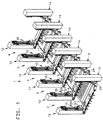
- a press line 1 is based on several successive workstations 2, 3, 4, 5, 6 for Machining of workpieces illustrated.
- For everyone Workstations 2 to 6 each have a sliding table 7, 8, 9, 10, 11, the inclusion of a no further illustrated tool is used.
- On both sides of the row formed by the sliding tables 7, 8, 9, 10, 11 are press stands 12, 14 arranged with the Sliding tables 7, 8, 9, 10, 11 stand on gap.
- the transfer unit 15 has two drive devices 16, 17 on each other with respect to a vertical plane are formed mirror-symmetrically and between each other hold a traverse 18, which is used as a carrier for Workpieces.
- a traverse 18 which is used as a carrier for Workpieces.
- the transfer press 1 is a body press there are 18 suction spiders 19, 20 on the crossbeams arranged, each spaced from each other Have suction cups 21. Due to the mirror symmetry between the drive devices 16, 17, the description of Corresponding drive device 16 for the drive device 17, with reference numerals corresponding for reference are used.
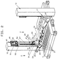
- a lever mechanism belongs to the drive device 16 23 with a swivel arm 24, one at one end Has receptacle 25 for the traverse 18.
- the recording 25 forms the output of the lever gear 23 and stores the Traverse 18 rotatable about a transverse to the direction of transport aligned axis - the so-called tilt axis.
- the swivel arm 24 is a guide 27, the one Sets pivot axis 28, mounted on a carriage 29.
- the length of the swivel arm 24, which in Figure 3 with L is designated.
- the carriage 29 can be driven by a or passive handlebar guidance to be replaced instead a linear guide represents a curved guide.
- the carriage 29 is vertical on a linear guide 31 adjustable.
- the carriage 29 runs free, i.e. it is not connected to any drive and in Vertical direction freely movable.
- the swivel arm 24 is on the carriage 29 freely pivotable. Thus at the level of Sliding tables 7, 8 and none below Drive devices available. If necessary, a Swivel motor can be provided for swiveling the traverses.
- the swivel arms 24 are driven by a Handlebar 32, whose length l is half the length L of the Swivel arm 24 is.
- the handlebar 32 is with the swivel arm 24 pivotally connected to a joint 33, the Joint axis 34 in the middle between the tilt axis K and the Pivot axis 28 is.
- the link 32 is connected at the end to a stub shaft 36, which is the output of one on a linear slide 37 mounted swivel drive 38 is.
- the carriage 37 is guided by a slide guide 39 in the vertical direction.
- the slide guide 39 is parallel to the slide guide 31 and how this is arranged on the press stand 12 or 14.
- the swivel drive 38 carried by the carriage 37 is by an actuator 41 and a reduction gear 43 formed, the output of the stub shaft 36 is.
- the carriage 37 is connected to a lifting drive 45, to which an actuator 46 and a downstream screw jack 47 belong. Both motors 41, 46 are subordinate the control of a central control device.
- a force generating device for example two pneumatic cylinders 51, 52, whose internal pressure is either essentially constant and / or possibly from the control device is controlled.
- the pneumatic cylinders 51, 52 are over Tension struts 53, 54 connected to the carriage 37.
- the transfer unit 15 described so far works as illustrated schematically in Figure 3 as follows:
- the control unit causes the servomotors 41, 46 to raise and lower the carriage 37 and to pivot the handlebar 32 such that the joint axis 34 runs through the distorted transfer curve K 0 illustrated in FIG. 3.
- the joint 33 forms the drive for the swivel arm 24. Its lower end is supported on the carriage 29, which thus forms the bearing for the swivel arm 24.
- the lever transmission from the drive at the joint 33 to the receptacle 25 creates the desired loop-shaped transfer curve K on the receptacle 25 and thus on the carrier means 18.
- the transfer curve K has a length in the transfer direction X which is twice as long as the length the curve K 0 in the transfer direction. Both curves are roughly the same in height.
- the swivel arm 24 thus translates into fast, that is to say the carrier means 18 moves considerably faster and is accelerated and braked more strongly than the joint 33 reached.
- the inert masses of these elements therefore impair the acceleration and braking of the carrier means 18 with reduced values.
- the drive device 16 presented also allowing good positioning accuracy.
- the vertical direction and the transport direction X are decoupled, ie a movement of the motor 41 is exclusively in an X movement and a movement of the motor 46 is exclusively in a pure Y movement implemented.
- Transfer unit 15 At rest and at the beginning of a work cycle of Transfer unit 15 is the swivel arm 24 from the handlebar 32 swiveled into vertical position.
- the tilt axis K is located in a first point A of the transfer curve K.
- the swivel drive 38 actuated by driving the motor 41 so that the Handlebar 32 to the left in Fig. 3, i.e. against the direction of transport X swings.
- the sled performs 37 a control of the motor 46 a lifting-lowering movement, so that the support means 18 with its tilt axis K Completed curve section B starting from path point A. and in an almost vertical lowering motion arrives at pickup point B.
- Deviating from the embodiment described above can the handlebar 32 also on a stationary Swivel drive to be attached.
- the height adjustment is then, for example, by a telescopic drive of the handlebar 32 accessible, which is then adjustable in length.
- a telescopic drive of the handlebar 32 accessible, which is then adjustable in length.
- Joint 33 can be arranged.
- the swivel arm however, it is subject to larger movements and accelerations.
- a swivel drive can also be attached to the Carriage 29 can be arranged and directly on the swivel arm 24 act. This both when the handlebar 32 is unchangeable in length and is mounted on a carriage 37 as well if the handlebar 32 is designed as a telescope and be Articulation point determined by a fixed swivel axis becomes. Regardless of how the swivel drive of the swivel arm 24 is realized in detail, the swivel arm 24 can also be designed as a telescope.
- the telescopic point can be both above and also arranged below the joint 33 and with a Be telescopic drive. Here it is possible to to dispense with the lower carriage 29. This design can lead to a reduced height, which also has advantages can have.
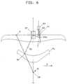
- a further modified embodiment of the Drive device 16 proceeds from that illustrated in FIG. 6 Kinematics.
- the handlebar 32 instead of that of the sled 37 carried swivel drive 38, the handlebar 32 with a lever arm 61 connected to it, which is connected to a carriage 63 via a connecting rod 62. This is guided in a linear guide, which is preferably parallel to the linear guide of the slide 37 is aligned.
- a drive of the carriage 63 causes a pivoting of the handlebar 32 as soon as it does not controlled synchronously with the drive of the carriage 37 becomes.
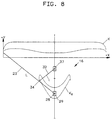
- FIG. 8 shows an embodiment of the drive device 16 illustrates in which the aspect ratios between the swivel arm 24 and the handlebar 32 different than previously described conditions.
- the length L of the swivel arm 24 exceeds the length l of the link 32 by more than double. This results in a larger translation.
- the guides and drives can according to all the variants and embodiments explained above be trained and arranged.
- the drive device 16 sort of hanging, i.e. 8 upside down in Fig. 8. This can mean if all drives and guides are as far above as possible the sliding tables 7, 8 are to be arranged.
- the drives of the sled can be assembled independently whether the carriage 37 is driven and the Carriage 29 runs freely, or whether the carriage 29 is driven is and the carriage 37 runs freely above the Lever gear can be arranged. You can also click on the Carriage 37, 29 are dispensed with when the swivel arm 24 designed as a telescope and thus the distance between the hinge axis 34 and the pivot axis 28 is variable.
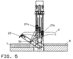
- FIGS. 4 and 5 Another embodiment of the transport and positioning unit 16 is shown in FIGS. 4 and 5. Training and storage of the swivel arm 24 and that of him worn traverse 18 matches the embodiment Fig. 2 match.
- the transfer unit 15 according to FIG. 4 differs however different from those described above by positioning the pivot axis 34 in space. To serve two links 32a, 32b, which on the joint 33 on the Swivel arm 24 are articulated. Both links 32a, 32b point the same hinge axis 34.
- the links 32a, 32b extend at an acute angle to each other away from the swivel arm 24 to slide 37a, 37b, which are connected to, for example, parallel linear guides the press stand 12 (14) are stored.
- slide 37a, 37b On the sledge 37a, 37b are, for example, the same length handlebars 32a, 32b pivoted freely.
- the slides 37a, 37b are each connected to a linear actuator 45a, 45b.
- These include high-speed motors 46a, 46b, which over Linear gear, e.g. screw jacks 47a, 47b on the Slides 37a, 37b act.
- a third link 32c which is also on the joint 33 or near it will result in one third carriage 37c, for example with an essentially constant, vertically upward force and is mounted on a vertical guide.
- the force generator Pneumatic cylinder 51 which on the tension strut 53rd is connected to the carriage 37c.
- the transfer curve K 0 is achieved on the joint axis 34 by the interaction of the lifting movement of the slides 37a, 37b.
- the swivel arm 24 converts the movement of the joint axis 34 into the transfer curve K.
- FIG. 7 is a kinematics illustrated, starting from the carriage 37, a parallelogram guide leads to the traverse 18.
- Parallel a link 32 ' is provided to the link 32, which is pivotally mounted on the carriage 37.
- To the Swivel arm 24 is pivotable about the hinge axis 34 short guide lever 71 articulated parallel to the imaginary connection of the opposite swivel axes the link 32, 32 'extends.
- the handlebar 32 ', the Length matches the length of the handlebar 32 is with the guide lever 71 pivotable at an axis 72 connected.
- the links 32, 32 ' form a parallelogram.
- the crosshead is tilted 18 determined by the orientation of the lever 73, the in every swivel position with the alignment of the connecting line between the upper ends of the links 32, 32 ' matches.
- the handlebar 32 'on the carriage an articulation point 74 may be connected, which with respect to the Carriage 37 is adjustable in height.
- a corresponding one Adjustment drive can be carried by the carriage 37. It is also possible to use the handlebar 32 'and / or the handlebar 24 'adjustable in length.
- the lever gear 23 takes over both the leadership and the drive of the carrier means 18, which thus the output of the lever gear forms.
Landscapes
- Engineering & Computer Science (AREA)
- Mechanical Engineering (AREA)
- Manipulator (AREA)
- Transmission Devices (AREA)
- Replacing, Conveying, And Pick-Finding For Filamentary Materials (AREA)
- Electrical Discharge Machining, Electrochemical Machining, And Combined Machining (AREA)
- Attitude Control For Articles On Conveyors (AREA)
- Multi-Process Working Machines And Systems (AREA)
Abstract
Description
- Fig. 1
- eine Pressenstrasse mit mehreren Arbeitsstationen, die durch Transfereinheiten miteinander verknüpft sind, in ausschnittsweiser perspektivischer Prinzipdarstellung,
- Fig. 2
- zwei Arbeitsstationen der Pressenstrasse nach Figur 1 und die dazwischen angeordnete Transfereinheit, in perspektivischer Darstellung, in einem anderen Maßstab,
- Fig. 3
- die Kinematik der Transfereinheit nach Figur 2, in schematischer Darstellung,
- Fig. 4
- eine abgewandelte Ausführungsform einer Transfereinheit zur Verknüpfung zweier Arbeitsstationen, in perspektivischer Darstellung,
- Fig. 5
- die Arbeitsstationen und die Transfereinheit nach Figur 4, in einer schematischen Seitenansicht,
- Fig. 6
- die Kinematik einer Transfereinheit nach dem in Figur 2 veranschaulichten Prinzip mit einer abgewandelten Ausführungsform eines Schwenkantriebs,
- Fig. 7
- die Kinematik einer Transfereinheit mit Parallelogrammführung für die Werkstückaufnahine, und
- Fig. 8
- die Kinematik einer abgewandelte Transfereinheit.
Claims (23)
- Transport- und/oder Positioniereinrichtung (15), insbesondere für den Werkstücktransfer,mit einer Antriebseinrichtung (16), die wenigstens ein Hebelgetriebe (23), mit einem Abtrieb (25) zum Antreiben und Positionieren eines Trägermittels (18) aufweist,
wobei zu dem Hebelgetriebe (23) ein Schwenkarm (24) gehört, dessen eines Ende den Abtrieb (25) bildet und mit dem Trägermittel (18) verbunden ist und der an zwei voneinander beabstandeten Verbindungsstellen (28, 34) mit einem Lager (27) und mit einem Antrieb (32, 33) verbunden ist,
wobei der Abstand zwischen der Lagerstelle (28) und der Antriebsstelle (34) kleiner ist, als der Abstand zwischen dem Abtrieb (25) und der Lagerstelle (28). - Einrichtung nach Anspruch 1, dadurch gekennzeichnet, dass der der Schwenkarm (24) derart geführt ist, dass der Abtrieb (25) eine schleifenförmige Bahn (K) durchläuft, die einen größeren Weg durchläuft, als der von der Lagerstelle (28) oder der Antriebsstelle (34) durchlaufene Weg.
- Einrichtung nach Anspruch 2, dadurch gekennzeichnet, dass die Bahn (K) innerhalb einer Vertikalebene verläuft.
- Einrichtung nach Anspruch 1, dadurch gekennzeichnet, dass der Schwenkarm (24) an dem Lager (27) um eine Horizontalachse (28) schwenkbar gelagert ist.
- Einrichtung nach Anspruch 1, dadurch gekennzeichnet, dass das Lager (27) des Schwenkarms (24) auf einer vorgegebenen, vorzugsweise geraden Bahn geführt ist.
- Einrichtung nach Anspruch 1, dadurch gekennzeichnet, dass die Verbindungsstelle (33), bei der der Antrieb (32) des Schwenkarms (24) mit dem Schwenkarm (24) verbunden ist, zwischen dem Lager (27) und dem Abtrieb (25) angeordnet ist.
- Einrichtung nach Anspruch 1, dadurch gekennzeichnet, dass der Antrieb (32) derart ausgebildet und geführt ist, dass die räumliche Lage der Verbindungsstelle (34) des Antriebs (32) mit dem Schwenkarm (24) von dem Antrieb (23) festgelegt ist.
- Einrichtung nach Anspruch 1, dadurch gekennzeichnet, dass der Antrieb (32) wenigstens einen Lenker (32) aufweist, über den der Schwenkarm (24) mit einer Führungseinrichtung (37), vorzugsweise einer Linearführungseinrichtung verbunden ist.
- Einrichtung nach Anspruch 8, dadurch gekennzeichnet, dass die Führungseinrichtung (37) mit einer Antriebseinheit (45) verbunden ist.
- Einrichtung nach Anspruch 8, dadurch gekennzeichnet, dass die Führungseinrichtung (37) eine Schlittenführung ist, an deren Schlitten (37) der Lenker (32) schwenkbar gelagert ist.
- Einrichtung nach Anspruch 10, dadurch gekennzeichnet, dass der Lenker (32) mit einem Schwenkantrieb (38) verbunden ist, mit dem die Schwenklage des Lenkers (32) festlegbar ist.
- Einrichtung nach Anspruch 11, dadurch gekennzeichnet, dass der Schwenkantrieb (38) von dem Schlitten (37) getragen ist.
- Einrichtung nach Anspruch 11, dadurch gekennzeichnet, dass der Schwenkantrieb (38) außerhalb (63) des Schlittens (37) angeordnet ist.
- Einrichtung nach Anspruch 1, dadurch gekennzeichnet, dass die Verbindungsstelle (34) zwischen dem Lenker (32) und dem Schwenkarm (24) mittig zwischen dem Lager (27) und dem Abtrieb (25) angeordnet ist.
- Einrichtung nach Anspruch 13, dadurch gekennzeichnet, dass der Schwenkantrieb an einem von der Drehachse des Lenkers (32) beabstandeten Stelle (62a) mit dem Lenker (32) verbunden ist, wobei der Schwenkantrieb vorzugsweise eine Führungseinrichtung (63) aufweist, deren Führungsrichtung parallel zu der Führungseinrichtung (37) des Lenkers (32) ausgerichtet ist, und wobei der Lenker (32) vorzugsweise als zweiarmiger Hebel ausgebildet ist, dessen eines Ende den Schwenkarm (24) führt und dessen anderes Ende mit dem Schwenkantrieb (62, 63) verbunden ist.
- Einrichtung nach Anspruch 1, dadurch gekennzeichnet, dass der Antrieb wenigstens zwei Lenker (32a, 32b) aufweist, über die der Schwenkarm (24) mit Führungseinrichtungen, vorzugsweise Linearführungseinrichtungen verbunden ist, wobei die beiden Lenker (32a, 32b) miteinander einen spitzen Winkel einschließen und an einer Verbindungsstelle um eine gemeinsame Schwenkachse (34) schwenkbar mit dem Schwenkarm (24) verbunden sind.
- Einrichtung nach Anspruch 16, dadurch gekennzeichnet, dass die beiden Führungseinrichtungen jeweils mit einer Antriebseinheit (45a, 45b) verbunden sind, wobei die Führungseinrichtungen Schlittenführungen sind, an deren Schlitten (37a, 37b) die Lenker (32a, 32b) frei schwenkbar gelagert sind.
- Einrichtung nach Anspruch 17, dadurch gekennzeichnet, dass die Führungseinrichtungen zueinander parallele Linearführungen sind.
- Einrichtung nach Anspruch 1 oder 8, dadurch gekennzeichnet, dass der Schwenkarm (24) und/oder der Lenker (32) teleskopierbar ausgebildet und mit einem Teleskopantrieb versehen ist.
- Einrichtung nach Anspruch 1, dadurch gekennzeichnet, dass der Schwenkarm (24) mit einer Einrichtung (24', 32', 71, 73) zur Kippausrichtung des Trägermittels (18) versehen ist.
- Einrichtung nach Anspruch 1, dadurch gekennzeichnet, dass der Schwenkarm (24) eine feststehende Riemenscheibe besitzt, die über einen Zahnriemen mit einer gleich großen Riemenscheibe, die fest mit dem Trägermittel (18) verbunden ist, verbunden ist und ein Verkippen des Trägermittels um eine horizontale Achse quer zur Transportrichtung verhindert.
- Einrichtung nach Anspruch 21, bei der sich die Riemenscheibe auf dem Schwenkarm (24) an der Verbindungsstelle (28) befindet.
- Einrichtung nach Anspruch 21 oder 22, bei der die Riemenscheibe auf dem Schwenkarm (24) nicht mehr fest mit dem Schwenkarm (24) verbunden ist, sondern von einem Motor zur gezielten Verkippung des Trägermittels angetrieben wird.
Applications Claiming Priority (2)
| Application Number | Priority Date | Filing Date | Title |
|---|---|---|---|
| DE19851744A DE19851744A1 (de) | 1998-11-10 | 1998-11-10 | Transport- und Positioniereinrichtung |
| DE19851744 | 1998-11-10 |
Publications (3)
| Publication Number | Publication Date |
|---|---|
| EP1000682A2 true EP1000682A2 (de) | 2000-05-17 |
| EP1000682A3 EP1000682A3 (de) | 2001-06-20 |
| EP1000682B1 EP1000682B1 (de) | 2004-01-21 |
Family
ID=7887268
Family Applications (1)
| Application Number | Title | Priority Date | Filing Date |
|---|---|---|---|
| EP99121917A Expired - Lifetime EP1000682B1 (de) | 1998-11-10 | 1999-11-05 | Transport- und Positioniereinrichtung |
Country Status (6)
| Country | Link |
|---|---|
| US (1) | US6382400B1 (de) |
| EP (1) | EP1000682B1 (de) |
| AT (1) | ATE258085T1 (de) |
| BR (1) | BR9905355A (de) |
| CA (1) | CA2289177A1 (de) |
| DE (2) | DE19851744A1 (de) |
Cited By (1)
| Publication number | Priority date | Publication date | Assignee | Title |
|---|---|---|---|---|
| CN104226836A (zh) * | 2013-06-06 | 2014-12-24 | 会田工程技术有限公司 | 伺服多工位送料装置及伺服多工位送料装置的控制方法 |
Families Citing this family (18)
| Publication number | Priority date | Publication date | Assignee | Title |
|---|---|---|---|---|
| TW200505606A (en) * | 2003-05-20 | 2005-02-16 | Ishikawajima Harima Heavy Ind | Panel transporting device |
| RU2336967C2 (ru) * | 2003-05-20 | 2008-10-27 | Исикавадзима-Харима Хэви Индастриз Ко., Лтд. | Устройство для транспортировки панели |
| JP4725003B2 (ja) * | 2003-05-20 | 2011-07-13 | 株式会社Ihi | パネル搬送装置 |
| US7168553B2 (en) * | 2003-11-13 | 2007-01-30 | Applied Materials, Inc. | Dynamically balanced substrate carrier handler |
| RU2337049C1 (ru) * | 2004-05-10 | 2008-10-27 | Исикавадзима-Харима Хэви Индастриз Ко., Лтд. | Устройство транспортирования панели |
| US7562765B2 (en) * | 2004-05-10 | 2009-07-21 | Ihi Corporation | Panel carrying device |
| JP5306161B2 (ja) * | 2009-12-16 | 2013-10-02 | アイダエンジニアリング株式会社 | ワーク搬送装置 |
| CN103506884B (zh) * | 2013-09-03 | 2016-01-20 | 宁夏共享集团有限责任公司 | 一种配套高端数控加工生产线的正向翻转送料机构 |
| DE102014117026B3 (de) * | 2014-11-20 | 2015-12-03 | Strothmann Machines & Handling GmbH | Transfervorrichtung |
| CN106882568A (zh) * | 2017-03-28 | 2017-06-23 | 苏州塞维拉上吴电梯轨道系统有限公司 | 一种电梯导轨输送线自动对中装置 |
| CN107161665B (zh) * | 2017-05-19 | 2023-05-02 | 常州君合科技股份有限公司 | 工件上料装置 |
| CN109986365B (zh) * | 2019-05-10 | 2023-05-12 | 厉雄伟 | 一种立式钢丝网架焊接生产线 |
| DE102019213871B4 (de) * | 2019-09-11 | 2022-08-18 | bavius technologie gmbh | Vorrichtung zum schwenken, wenden und wechseln von werkstück-paletten an einem horizontal-bearbeitungszentrum, sowie palettenträger |
| DE102019213870B4 (de) * | 2019-09-11 | 2022-08-18 | bavius technologie gmbh | Vorrichtung zum schwenken, wenden und wechseln von werkstück-paletten, sowie horizontal-bearbeitungszentrum |
| DE102020112613B3 (de) * | 2020-05-11 | 2021-08-19 | Aida Europe Gmbh | Transfersystem für Pressen und Pressenanordnung |
| CN115091081B (zh) * | 2022-06-25 | 2025-02-11 | 长沙佳顺玛钢件有限公司 | 一种便捷式焊接装置 |
| CN115744114A (zh) * | 2022-12-06 | 2023-03-07 | 一汽丰田汽车有限公司 | 运搬中转车 |
| CN120517823B (zh) * | 2025-07-23 | 2025-09-16 | 苏州青林自动化科技有限公司 | 一种辅助平整的码垛装置及自动码垛系统 |
Family Cites Families (17)
| Publication number | Priority date | Publication date | Assignee | Title |
|---|---|---|---|---|
| US3991885A (en) * | 1975-01-27 | 1976-11-16 | Warren William H | Path control means for a swivel operated article transfer device |
| DE3040655C2 (de) * | 1980-10-29 | 1984-03-29 | Maschinenfabrik Müller-Weingarten AG, 7987 Weingarten | Be- und/oder Entladegerät für Pressen, Stanzen o.dgl. Werkzeugmaschinen |
| US4496280A (en) * | 1982-12-22 | 1985-01-29 | Brems John Henry | Workpiece transfer mechanism |
| US4490091A (en) * | 1983-03-29 | 1984-12-25 | Brems John Henry | Slave rotate mechanism for mechanical hands of gantry type transfer system |
| JPS59191528A (ja) * | 1983-04-14 | 1984-10-30 | Toyota Motor Corp | 加工装置のワ−ク搬送装置 |
| JPS63207429A (ja) * | 1987-02-23 | 1988-08-26 | Honda Motor Co Ltd | プレスマシンのワ−ク搬送装置 |
| US4806070A (en) * | 1987-04-13 | 1989-02-21 | General Electric Company | Article transfer apparatus |
| SE465863B (sv) * | 1989-07-13 | 1991-11-11 | Volvo Ab | Oeverfoeringsanordning vid presslinje |
| US5215181A (en) * | 1991-01-02 | 1993-06-01 | Blatt John A | Dual-belt shuttle unit |
| US5174709A (en) * | 1991-03-06 | 1992-12-29 | Leland D. Blatt | Workpiece transfer device |
| US5452981A (en) * | 1991-03-06 | 1995-09-26 | Leland D. Blatt | Automatic tool changer |
| DE4237312A1 (de) * | 1992-11-05 | 1994-05-11 | Schuler Gmbh L | Transferpresse o. dgl. Umformmaschine |
| US5359875A (en) * | 1993-05-14 | 1994-11-01 | Amsd Partnership | Apparatus and method for transferring and forming parts in a press |
| DE19628333A1 (de) * | 1996-07-13 | 1998-01-15 | Schuler Pressen Gmbh & Co | Umsetzeinrichtung für Blechteile in einer Pressenanlage |
| DK82796A (da) * | 1996-08-02 | 1998-02-03 | Tetra Lavel Food Hoyer | Overføringsindretning til aflevering af produkter, især spiseisprodukter, til en underliggende transportør |
| US5899108A (en) * | 1996-12-19 | 1999-05-04 | Schuler Pressen Gmbh & Co. | Flexible multi-axis transfer device |
| DE19728361A1 (de) * | 1997-07-03 | 1999-01-07 | Schuler Pressen Gmbh & Co | Mehrstationenpresse zum Umformen von Blechteilen |
-
1998
- 1998-11-10 DE DE19851744A patent/DE19851744A1/de not_active Withdrawn
-
1999
- 1999-11-05 EP EP99121917A patent/EP1000682B1/de not_active Expired - Lifetime
- 1999-11-05 AT AT99121917T patent/ATE258085T1/de not_active IP Right Cessation
- 1999-11-05 DE DE59908360T patent/DE59908360D1/de not_active Expired - Lifetime
- 1999-11-09 CA CA002289177A patent/CA2289177A1/en not_active Abandoned
- 1999-11-10 BR BR9905355-1A patent/BR9905355A/pt not_active Application Discontinuation
- 1999-11-10 US US09/437,256 patent/US6382400B1/en not_active Expired - Fee Related
Cited By (1)
| Publication number | Priority date | Publication date | Assignee | Title |
|---|---|---|---|---|
| CN104226836A (zh) * | 2013-06-06 | 2014-12-24 | 会田工程技术有限公司 | 伺服多工位送料装置及伺服多工位送料装置的控制方法 |
Also Published As
| Publication number | Publication date |
|---|---|
| DE59908360D1 (de) | 2004-02-26 |
| EP1000682B1 (de) | 2004-01-21 |
| DE19851744A1 (de) | 2000-05-11 |
| EP1000682A3 (de) | 2001-06-20 |
| CA2289177A1 (en) | 2000-05-10 |
| BR9905355A (pt) | 2000-08-29 |
| ATE258085T1 (de) | 2004-02-15 |
| US6382400B1 (en) | 2002-05-07 |
Similar Documents
| Publication | Publication Date | Title |
|---|---|---|
| EP1000682B1 (de) | Transport- und Positioniereinrichtung | |
| EP0850709B1 (de) | Transfereinrichtung und Mehrstationenpresse | |
| EP0671228B1 (de) | Transporteinrichtung für Werkstücke in einer Presse | |
| DE102004018059B4 (de) | Transfereinrichtung und Transferverfahren | |
| EP3615458B1 (de) | Umsetzeinrichtung | |
| WO2002018073A2 (de) | Gelenkarm-transportsystem | |
| EP0672480A1 (de) | Transportsystem | |
| EP0850710B1 (de) | Flexibler Mehrachstransfer | |
| DE3817117C2 (de) | ||
| DE19628556A1 (de) | Vorrichtung zur Entnahme und Zuführung von Formteilen | |
| WO2005075123A1 (de) | Transportvorrichtung für werkstücke durch pressenanlagen | |
| EP1000681B1 (de) | Transfereinrichtung mit kombiniertem Antrieb | |
| EP0901848B1 (de) | Transferpressen mit automatischem Toolingwechsel | |
| EP1704003A1 (de) | Transportvorrichtung | |
| EP1000683A2 (de) | Positioniereinrichtung mit Gewichtsausgleich | |
| EP1123761B1 (de) | Horizontales Transportsystem | |
| DE102004023525B4 (de) | Vorrichtung zum schrittweisen Verschieben von Werkstücken | |
| DE3439908A1 (de) | Maschinen zum auffalten von kartons aus ebenen zuschnitten | |
| EP1000680B1 (de) | Modulare Transfereinrichtung mit Schwenk- und Linearantrieben | |
| EP0507098B1 (de) | Transporteinrichtung zum Transportieren von grossflächigen Teilen in einer Stufenpresse | |
| EP1280622B1 (de) | Transfereinrichtung und verfahren zur steuerung einer transfereinrichtung | |
| EP0597386B1 (de) | Einrichtung zum Umsetzen von Blechteilen in einer Pressenanlage | |
| EP1048373A2 (de) | Orientierstation mit Stabgetriebe | |
| DE3217521A1 (de) | Vorrichtung fuer den transfer von werkstuecken | |
| DE2731579A1 (de) | Stapelvorrichtung fuer profilstaebe aus stahl |
Legal Events
| Date | Code | Title | Description |
|---|---|---|---|
| PUAI | Public reference made under article 153(3) epc to a published international application that has entered the european phase |
Free format text: ORIGINAL CODE: 0009012 |
|
| AK | Designated contracting states |
Kind code of ref document: A2 Designated state(s): AT BE CH CY DE DK ES FI FR GB GR IE IT LI LU MC NL PT SE |
|
| AX | Request for extension of the european patent |
Free format text: AL;LT;LV;MK;RO;SI |
|
| PUAL | Search report despatched |
Free format text: ORIGINAL CODE: 0009013 |
|
| AK | Designated contracting states |
Kind code of ref document: A3 Designated state(s): AT BE CH CY DE DK ES FI FR GB GR IE IT LI LU MC NL PT SE |
|
| AX | Request for extension of the european patent |
Free format text: AL;LT;LV;MK;RO;SI |
|
| RIC1 | Information provided on ipc code assigned before grant |
Free format text: 7B 21D 43/00 A, 7B 21D 43/22 B, 7B 21D 43/05 B |
|
| 17P | Request for examination filed |
Effective date: 20011010 |
|
| 17Q | First examination report despatched |
Effective date: 20011130 |
|
| AKX | Designation fees paid |
Free format text: AT BE CH CY DE DK ES FI FR GB GR IE IT LI LU MC NL PT SE |
|
| GRAH | Despatch of communication of intention to grant a patent |
Free format text: ORIGINAL CODE: EPIDOS IGRA |
|
| GRAS | Grant fee paid |
Free format text: ORIGINAL CODE: EPIDOSNIGR3 |
|
| GRAA | (expected) grant |
Free format text: ORIGINAL CODE: 0009210 |
|
| AK | Designated contracting states |
Kind code of ref document: B1 Designated state(s): AT BE CH CY DE DK ES FI FR GB GR IE IT LI LU MC NL PT SE |
|
| PG25 | Lapsed in a contracting state [announced via postgrant information from national office to epo] |
Ref country code: NL Free format text: LAPSE BECAUSE OF FAILURE TO SUBMIT A TRANSLATION OF THE DESCRIPTION OR TO PAY THE FEE WITHIN THE PRESCRIBED TIME-LIMIT Effective date: 20040121 Ref country code: IT Free format text: LAPSE BECAUSE OF FAILURE TO SUBMIT A TRANSLATION OF THE DESCRIPTION OR TO PAY THE FEE WITHIN THE PRESCRIBED TIME-LIMIT;WARNING: LAPSES OF ITALIAN PATENTS WITH EFFECTIVE DATE BEFORE 2007 MAY HAVE OCCURRED AT ANY TIME BEFORE 2007. THE CORRECT EFFECTIVE DATE MAY BE DIFFERENT FROM THE ONE RECORDED. Effective date: 20040121 Ref country code: IE Free format text: LAPSE BECAUSE OF FAILURE TO SUBMIT A TRANSLATION OF THE DESCRIPTION OR TO PAY THE FEE WITHIN THE PRESCRIBED TIME-LIMIT Effective date: 20040121 Ref country code: FI Free format text: LAPSE BECAUSE OF FAILURE TO SUBMIT A TRANSLATION OF THE DESCRIPTION OR TO PAY THE FEE WITHIN THE PRESCRIBED TIME-LIMIT Effective date: 20040121 Ref country code: CY Free format text: LAPSE BECAUSE OF FAILURE TO SUBMIT A TRANSLATION OF THE DESCRIPTION OR TO PAY THE FEE WITHIN THE PRESCRIBED TIME-LIMIT Effective date: 20040121 |
|
| REG | Reference to a national code |
Ref country code: GB Ref legal event code: FG4D Free format text: NOT ENGLISH |
|
| REG | Reference to a national code |
Ref country code: CH Ref legal event code: EP |
|
| REG | Reference to a national code |
Ref country code: IE Ref legal event code: FG4D Free format text: GERMAN |
|
| REF | Corresponds to: |
Ref document number: 59908360 Country of ref document: DE Date of ref document: 20040226 Kind code of ref document: P |
|
| PG25 | Lapsed in a contracting state [announced via postgrant information from national office to epo] |
Ref country code: SE Free format text: LAPSE BECAUSE OF FAILURE TO SUBMIT A TRANSLATION OF THE DESCRIPTION OR TO PAY THE FEE WITHIN THE PRESCRIBED TIME-LIMIT Effective date: 20040421 Ref country code: GR Free format text: LAPSE BECAUSE OF FAILURE TO SUBMIT A TRANSLATION OF THE DESCRIPTION OR TO PAY THE FEE WITHIN THE PRESCRIBED TIME-LIMIT Effective date: 20040421 Ref country code: DK Free format text: LAPSE BECAUSE OF FAILURE TO SUBMIT A TRANSLATION OF THE DESCRIPTION OR TO PAY THE FEE WITHIN THE PRESCRIBED TIME-LIMIT Effective date: 20040421 |
|
| PG25 | Lapsed in a contracting state [announced via postgrant information from national office to epo] |
Ref country code: ES Free format text: LAPSE BECAUSE OF FAILURE TO SUBMIT A TRANSLATION OF THE DESCRIPTION OR TO PAY THE FEE WITHIN THE PRESCRIBED TIME-LIMIT Effective date: 20040502 |
|
| GBT | Gb: translation of ep patent filed (gb section 77(6)(a)/1977) |
Effective date: 20040423 |
|
| NLV1 | Nl: lapsed or annulled due to failure to fulfill the requirements of art. 29p and 29m of the patents act | ||
| REG | Reference to a national code |
Ref country code: IE Ref legal event code: FD4D |
|
| ET | Fr: translation filed | ||
| PG25 | Lapsed in a contracting state [announced via postgrant information from national office to epo] |
Ref country code: LU Free format text: LAPSE BECAUSE OF NON-PAYMENT OF DUE FEES Effective date: 20041105 Ref country code: AT Free format text: LAPSE BECAUSE OF NON-PAYMENT OF DUE FEES Effective date: 20041105 |
|
| PLBE | No opposition filed within time limit |
Free format text: ORIGINAL CODE: 0009261 |
|
| STAA | Information on the status of an ep patent application or granted ep patent |
Free format text: STATUS: NO OPPOSITION FILED WITHIN TIME LIMIT |
|
| PG25 | Lapsed in a contracting state [announced via postgrant information from national office to epo] |
Ref country code: MC Free format text: LAPSE BECAUSE OF NON-PAYMENT OF DUE FEES Effective date: 20041130 Ref country code: LI Free format text: LAPSE BECAUSE OF NON-PAYMENT OF DUE FEES Effective date: 20041130 Ref country code: CH Free format text: LAPSE BECAUSE OF NON-PAYMENT OF DUE FEES Effective date: 20041130 Ref country code: BE Free format text: LAPSE BECAUSE OF NON-PAYMENT OF DUE FEES Effective date: 20041130 |
|
| 26N | No opposition filed |
Effective date: 20041022 |
|
| BERE | Be: lapsed |
Owner name: *SCHULER PRESSEN G.M.B.H. & CO. K.G. Effective date: 20041130 |
|
| REG | Reference to a national code |
Ref country code: CH Ref legal event code: PL |
|
| BERE | Be: lapsed |
Owner name: *SCHULER PRESSEN G.M.B.H. & CO. K.G. Effective date: 20041130 |
|
| PG25 | Lapsed in a contracting state [announced via postgrant information from national office to epo] |
Ref country code: PT Free format text: LAPSE BECAUSE OF NON-PAYMENT OF DUE FEES Effective date: 20040621 |
|
| PGFP | Annual fee paid to national office [announced via postgrant information from national office to epo] |
Ref country code: DE Payment date: 20101110 Year of fee payment: 12 |
|
| PGFP | Annual fee paid to national office [announced via postgrant information from national office to epo] |
Ref country code: GB Payment date: 20101123 Year of fee payment: 12 |
|
| PGFP | Annual fee paid to national office [announced via postgrant information from national office to epo] |
Ref country code: FR Payment date: 20111125 Year of fee payment: 13 |
|
| GBPC | Gb: european patent ceased through non-payment of renewal fee |
Effective date: 20121105 |
|
| REG | Reference to a national code |
Ref country code: FR Ref legal event code: ST Effective date: 20130731 |
|
| REG | Reference to a national code |
Ref country code: DE Ref legal event code: R119 Ref document number: 59908360 Country of ref document: DE Effective date: 20130601 |
|
| PG25 | Lapsed in a contracting state [announced via postgrant information from national office to epo] |
Ref country code: DE Free format text: LAPSE BECAUSE OF NON-PAYMENT OF DUE FEES Effective date: 20130601 |
|
| PG25 | Lapsed in a contracting state [announced via postgrant information from national office to epo] |
Ref country code: FR Free format text: LAPSE BECAUSE OF NON-PAYMENT OF DUE FEES Effective date: 20121130 Ref country code: GB Free format text: LAPSE BECAUSE OF NON-PAYMENT OF DUE FEES Effective date: 20121105 |