EP1000709A2 - Accessoire pour placer des moyens de fixation pour des outils à entraínement rotatif - Google Patents
Accessoire pour placer des moyens de fixation pour des outils à entraínement rotatif Download PDFInfo
- Publication number
- EP1000709A2 EP1000709A2 EP99402757A EP99402757A EP1000709A2 EP 1000709 A2 EP1000709 A2 EP 1000709A2 EP 99402757 A EP99402757 A EP 99402757A EP 99402757 A EP99402757 A EP 99402757A EP 1000709 A2 EP1000709 A2 EP 1000709A2
- Authority
- EP
- European Patent Office
- Prior art keywords
- collar
- stem
- fastener
- mounting
- driving
- Prior art date
- Legal status (The legal status is an assumption and is not a legal conclusion. Google has not performed a legal analysis and makes no representation as to the accuracy of the status listed.)
- Granted
Links
Images

Classifications
-
- B—PERFORMING OPERATIONS; TRANSPORTING
- B25—HAND TOOLS; PORTABLE POWER-DRIVEN TOOLS; MANIPULATORS
- B25F—COMBINATION OR MULTI-PURPOSE TOOLS NOT OTHERWISE PROVIDED FOR; DETAILS OR COMPONENTS OF PORTABLE POWER-DRIVEN TOOLS NOT PARTICULARLY RELATED TO THE OPERATIONS PERFORMED AND NOT OTHERWISE PROVIDED FOR
- B25F5/00—Details or components of portable power-driven tools not particularly related to the operations performed and not otherwise provided for
-
- B—PERFORMING OPERATIONS; TRANSPORTING
- B25—HAND TOOLS; PORTABLE POWER-DRIVEN TOOLS; MANIPULATORS
- B25B—TOOLS OR BENCH DEVICES NOT OTHERWISE PROVIDED FOR, FOR FASTENING, CONNECTING, DISENGAGING, OR HOLDING
- B25B13/00—Spanners; Wrenches
- B25B13/02—Spanners; Wrenches with rigid jaws
- B25B13/06—Spanners; Wrenches with rigid jaws of socket type
-
- B—PERFORMING OPERATIONS; TRANSPORTING
- B25—HAND TOOLS; PORTABLE POWER-DRIVEN TOOLS; MANIPULATORS
- B25B—TOOLS OR BENCH DEVICES NOT OTHERWISE PROVIDED FOR, FOR FASTENING, CONNECTING, DISENGAGING, OR HOLDING
- B25B23/00—Details of, or accessories for, spanners, wrenches, screwdrivers
- B25B23/0007—Connections or joints between tool parts
- B25B23/0035—Connection means between socket or screwdriver bit and tool
Definitions
- This invention pertains to a fastener-driving accessory useful with a rotary driving tool, which may be electrically or pneumatically powered.
- a fastener-driving accessory useful with a rotary driving tool, which may be electrically or pneumatically powered.
- two interchangeable collars are provided, namely a fastener-driving collar and a bit-mounting collar.
- the fastener-driving collar can have two interchangeable sockets, either of which can serve as a fastener-driving socket.
- the bit-mounting collar can mount a fastener-driving bit of a type known heretofore.
- This invention addresses a recognized need for an improved means for interchanging fastener-driving elements, such as socket heads and driving bits, in a rotary power tool, which may be electrically or pneumatically powered, particularly but not exclusively in a rotary power tool equipped with a fastener-driving element carried by an elongate member, as discussed above.
- the fastener-driving accessory useful with a rotary power tool, which may be electrically or pneumatically powered.
- the fastener-driving accessory comprises a collar-driving stem and a collar, either a fastener-driving collar or a bit-mounting collar, according to claim 1.
- the collardriving stem is connected to a tool-drivable stem, by a quill.
- the collar-driving stem defines an axis and has a collar-mounting portion having a polygonal cross-section. It is preferred that the collar-mounting portion has a hexagonal cross-section.
- Each of the fastener-driving and bit-mounting collars defines an axis.
- the fastener-driving collar defines two axially aligned sockets, each having a polygonal cross-section, which is similar to but larger than the polygonal cross-section of the collar-mounting portion.
- the axially aligned sockets are interchangeable to serve respectively as a stem-receiving socket and as a fastener-driving socket.
- the fastener-driving collar has two opposite ends and one continuous passage defining the axially aligned sockets, extending between the opposite ends, and having a polygonal cross-section conforming to the polygonal cross-sections of the axially aligned sockets.
- the collar-mounting portion of the collar-driving stem is adapted to be non-rotatably plugged more than half way through the continuous passage when plugged into either of the axially aligned sockets so as to protect the polygonal cross-section of an intermediate portion of the fastener-driving collar against wearing as either of the axially aligned sockets wears.
- the fastener driving accessory may further comprise a bit mounting collar, according to claim 5, and may be combined with a fastener driving bit, according to claim 7.
- the fastener-driving and bit-mounting collars are interchangeable. Means are provided for securing whichever collar is used removably on the collar-driving stem when the collar-mounting portion is plugged into whichever socket serves as the stem-receiving socket.
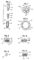
- a fastener-driving accessory 10 constituting a preferred embodiment of this invention is useful with a rotary driving tool, either electrically powered or pneumatically powered, which is not shown except for a chuck C shown in broken lines.
- the fastener-driving accessory 10 comprises a tool-drivable stem 20, a collar-mounting stem 30, a tubular quill 40 connecting the respective stems 20, 30, and two interchangeable collars, namely a fastener-driving collar 50 adapted to drive a fastener of a known type, such as a hex-head fastener 100, and a bit-mounting collar 60 adapted to mount a fastener-driving bit of a known type, such as a fastener-driving bit 120 adapted to drive Phillips-head fasteners (not shown).
- the fastener-driving accessory 10 can be advantageously employed in a rotary driving tool, such as a screw gun, which is adapted to be conveniently operated by a standing operator, as exemplified in U.S. patent No. 4,236,555 .
- the fastener-driving accessory 10 also can be advantageously employed in a roofing washer-dispensing and fastener-driving machine, as exemplified in U.S. Patents N° 5,445,297, N° 5,555,780, and N° 5,584,415.
- the tool-drivable stem 20 has a hexagonal cross-section, except for a circumferential recess 22 near one end 24 of the stem 20, and except for a hole or holes to be later described.
- the circumferential recess 22 enables the stem 20 to coact with a known detent (not shown) in the tool chuck C when the same end 24 of the stem 20 is plugged partly into the tool chuck C.
- the other end 26 of the stem 20 is plugged partly into one end of the tubular quill 40.
- the stem 20 is secured to the quill 40 by a roll pin 28 driven through a suitably sized hole in the quill 40, through a suitably sized cross-bore in the stem 20, and through a suitably sized, diametrically opposed hole in the quill 40.
- the diametrically opposed holes provided in the tubular quill 40 for the roll pin 28 are oversized, as compared to the roll pin 28. Acordingly, when such a load is applied, the roll pin 28 is not stressed by the applied load and tendencies of the roll pin 28 to break are reduced.
- the collar-mounting stem 30 has an essentially identical, hexagonal cross-section.
- One end 32 of the stem 30 is plugged partly into the other end of the tubular quill 40, with a sliding fit, and a collar-mounting portion 34 including the other end 36 of the stem 30 projects from the quill 40.
- the stem 40 is secured to the quill 40 by a roll pin 38 driven through a suitably sized hole in the quill 40, through a suitably sized cross-bore in the stem 20, and through a suitably sized, diametrically opposed hole in the quill 40.
- the collar-mounting portion 34 of the stem 30 projects from the quill 40 and is used to mount a selected one of the interchangeable collars.
- the fastener-driving collar 50 has a passage 52 extending continuously through the collar 50 and defining two axially aligned sockets 54, 56, which open respectively at the opposite ends of the collar 50.
- the sockets 54, 56 are interchangeable to serve respectively as a stem-receiving socket and as a fastener-driving socket.
- the socket 54 serves as the stem-receiving socket
- the socket 56 serves as the fastener-driving socket.
- the passage 52 has a hexagonal cross-section, which is similar to but larger than the hexagonal cross-section of the collar-mounting stem 30.
- each of the sockets 54, 56 has a hexagonal cross-section, which is similar to but larger than the hexagonal cross-section of the collar-mounting stem 30.
- the collar-mounting portion 34 of the collar-mounting stem 30 is plugged partly and non-rotatably into whichever of the sockets 54, 56, serves as the stem-receiving socket, with a sliding fit and more than halfway through the passage 52, so as to cause the stem 30 and the collar 50 to be conjointly rotatable.
- the collar-mounting portion 34 of the stem 30 is plugged partly and non-rotatably into the socket 54, more than halfway through the passage 52.
- the collar-mounting stem 30 is secured to the fastener-driving collar 50 by a spring-biased pintle 70 mounted operatively in a radial socket 72 of the stem 30, biased in a radially outward direction by a coil spring 74 disposed in the socket 72, retained by a deformed margin 76 of the socket 72, and projecting in a radially outward direction, into a hole 78 in the collar 50.
- the hole 78 is centered approximately halfway between the opposite ends of the collar 50.
- the spring-biased pintle 70 secures the stem 30 to the collar 50 but enables the collar 50 to be readily removed, as when it is desired to interchange the collar 50 with the bit-mounting collar 60.
- the spring-biased pintle 70 is depressed by a pointed instrument (not shown) to remove the collar 50.
- the collar-mounting stem 30 is secured removably to the fastener-driving collar 50 by a roll pin 80 driven through a suitably sized hole 82 in the collar 50, through a suitably sized cross-bore 84 in the stem 30, and through a suitably sized, diametrically opposed hole 86 in the collar 50.
- the roll pin 80 is driven by an impact tool (not shown) to remove the collar 50.
- the collar-mounting stem 30 is secured removably to the fastener-driving collar 50 by a set screw 90 driven through a suitably sized, threaded hole 92 in the collar 50, through a suitably sized, unthreaded cross-bore 94 in the stem 30, and through a suitably sized, diametrically opposed, threaded hole 96 in the collar 50.
- the set screw 90 is unthreaded to remove the collar 50.
- Whichever of the sockets 54, 56, serves as the fastener-driving socket is adapted to receive and coact with the head of a hex-head fastener of a known type, so as to drive the fastener rotatably when the fastener-driving accessory is driven rotatably by the tool chuck C.
- the socket 54 serving as the fastener-driving socket receives and coacts with the head 102 of the hex-head fastener 100, so as to drive the fastener 100 rotatably when the fastener-driving accessory is driven rotatably by the tool chuck C.
- the fastener-driving collar 50 is reversible so as to interchange the sockets 54, 56. Effectively, the useful life of the collar 50 is doubled, as compared to the useful life that the collar 50 would have if the collar 50 were to have a single socket.
- an intermediate portion 58 of the passage 52 does not become worn but continues to have a hexagonal cross-section except for the hole 78, the holes 82, 86, or the holes 92, 96 (see Figures 10, 11, and 12) so that the collar 50 continues to be conjointly rotatable with the stem 30, even if whichever of the sockets 54, 56, serves as the fastener-driving socket has become worn.
- the bit-mounting collar 60 has a stem-receiving end 62 and a bit-mounting end 64.
- the collar 60 defines a stem-receiving socket 66 opening at the stem-receiving end 62 and having a hexagonal cross-section, which is similar to but larger than the hexagonal cross-section of the collar-mounting stem 30.
- the collar 60 has an axial passage 68 extending between the bit-mounting end 64 and the socket 66 and having a circular cross-section with a cross-sectional area smaller than the cross-sectional area of the hexagonal cross-section of the socket 66.
- the collar-mounting portion 34 of the collar-mounting stem 30 is plugged into the socket 66, which has sufficient axial length for such portion 34 to be axially spaced from the axial passage 68 when plugged into the socket 66.
- the bit-mounting collar 60 is secured to the collar-mounting stem 30 by the spring-biased pintle 70, which projects in a radially outward direction, into a hole 98 in the collar 60.
- the collar 60 can be alternatively secured to the stem 30, essentially as the collar 50 can be alternatively secured to the stem 30, by a roll pin (not shown) similar to the roll pin 80 shown in Figures 10 and 11 or by a set screw (not shown) similar to the set screw 90 shown in Figure 12.
- the bit-mounting collar 60 is adapted to mount a fastener-driving bit of a known type, such as the fastener-driving bit 120.
- the fastener-driving bit 120 has a socket-fitting portion 122 and a fastener-driving portion 124, which has a fastener-driving tip 126.
- the socket-fitting portion 122 has a hexagonal cross-section conforming to the hexagonal cross-section of the collar-mounting stem 30.
- the fastener-driving portion 124 has an axial length greater than the axial length of the axial passage 68 of the bit-mounting collar 60 and has cross-sectional shapes varying along the axial length of such portion 124 but adapting such portion to extend through the passage 68.
- the socket-fitting portion 122 is plugged slidably into the stem-receiving socket 66 of the bit-mounting collar 60 so that the fastener-driving portion 124 precedes the socket-fitting portion 122 and extends through the passage 68, whereby the fastener-driving tip 126 projects axially from the collar 60, before the collar-mounting portion 34 of the collar-mounting stem 30 is plugged into the socket 66.
- the fastener-driving bit 120 defines six three-sided surfaces 130, each having two straight sides meeting at a 120° angle and a concave side conforming to a 120° circular arc.
- the bit-mounting collar 60 defines six substantially similar, slightly larger surfaces 140. When the bit 120 is mounted to the collar 60, the three-sided surfaces 130 of the bit engage the slightly larger surfaces 140 of the collar 60, so as to prevent the bit 120 from being withdrawn from the collar 60, through the passage 68.
Landscapes
- Engineering & Computer Science (AREA)
- Mechanical Engineering (AREA)
- Portable Nailing Machines And Staplers (AREA)
- Details Of Spanners, Wrenches, And Screw Drivers And Accessories (AREA)
- Earth Drilling (AREA)
- Food-Manufacturing Devices (AREA)
- Perforating, Stamping-Out Or Severing By Means Other Than Cutting (AREA)
- Insertion Pins And Rivets (AREA)
Applications Claiming Priority (2)
| Application Number | Priority Date | Filing Date | Title |
|---|---|---|---|
| US09/192,049 US6282998B1 (en) | 1998-11-13 | 1998-11-13 | Fastener-driving accessory for rotary driving tool |
| US192049 | 1998-11-13 |
Publications (3)
| Publication Number | Publication Date |
|---|---|
| EP1000709A2 true EP1000709A2 (fr) | 2000-05-17 |
| EP1000709A3 EP1000709A3 (fr) | 2002-05-22 |
| EP1000709B1 EP1000709B1 (fr) | 2004-07-21 |
Family
ID=22708023
Family Applications (1)
| Application Number | Title | Priority Date | Filing Date |
|---|---|---|---|
| EP99402757A Expired - Lifetime EP1000709B1 (fr) | 1998-11-13 | 1999-11-05 | Accessoire pour placer des moyens de fixation pour des outils à entraínement rotatif |
Country Status (11)
| Country | Link |
|---|---|
| US (1) | US6282998B1 (fr) |
| EP (1) | EP1000709B1 (fr) |
| JP (1) | JP2000141237A (fr) |
| KR (1) | KR20000034953A (fr) |
| CN (1) | CN1089052C (fr) |
| AT (1) | ATE271443T1 (fr) |
| CA (1) | CA2284329C (fr) |
| DE (1) | DE69918774T2 (fr) |
| ES (1) | ES2226312T3 (fr) |
| NO (1) | NO995515L (fr) |
| TW (1) | TW418151B (fr) |
Families Citing this family (15)
| Publication number | Priority date | Publication date | Assignee | Title |
|---|---|---|---|---|
| US6602260B2 (en) * | 2001-02-02 | 2003-08-05 | Ams Research Corporation | Powered bone screw device |
| CA98829S (en) | 2002-03-04 | 2004-08-31 | Maxtech Mfg Inc | Screw guide |
| USD525101S1 (en) | 2002-03-04 | 2006-07-18 | Maxtech Manufacturing, Inc. | Screw guide |
| US6981976B1 (en) * | 2002-05-13 | 2006-01-03 | Biomet, Inc. | Method and apparatus for inserting and countersinking a modular screw |
| US7127972B2 (en) * | 2003-03-05 | 2006-10-31 | Klein David T | Method and apparatus for attaching a rod member to a remote surface |
| US20040231468A1 (en) * | 2003-05-23 | 2004-11-25 | Mark Odachowski | Hand or automatic driven tool for attaching screwed anchors |
| US6848346B1 (en) | 2003-07-09 | 2005-02-01 | Illinois Tool Work Inc | Hurricane shutter fastener installation bit |
| US7077037B2 (en) * | 2003-10-31 | 2006-07-18 | Spx Corporation | Apparatus and method for removing a bolt from an assembly |
| US7947047B2 (en) * | 2005-06-20 | 2011-05-24 | Ams Research Corporation | Medical screwdrivers and methods |
| US20090288524A1 (en) * | 2008-05-23 | 2009-11-26 | Jayson Michael Vasi | Rodrunner |
| US20160028202A1 (en) | 2014-07-22 | 2016-01-28 | Milwaukee Electric Tool Corporation | Hand tools |
| CN106005427A (zh) * | 2016-06-27 | 2016-10-12 | 广州飞机维修工程有限公司 | 航空座椅前脚底座装配工具 |
| US11143480B1 (en) * | 2019-03-21 | 2021-10-12 | Alfred T. R. Wilson | Arms power cleaning lubrication coupler and method |
| US11554423B2 (en) * | 2021-02-17 | 2023-01-17 | Ricardo Godina | Power drill accessories |
| TWI868944B (zh) * | 2023-09-22 | 2025-01-01 | 廖秉晟 | 深孔套筒驅動桿結構改良 |
Family Cites Families (23)
| Publication number | Priority date | Publication date | Assignee | Title |
|---|---|---|---|---|
| US3965510A (en) | 1975-05-09 | 1976-06-29 | Illinois Tool Works Inc. | Combination drilling and wrenching tool |
| US3960191A (en) | 1975-06-17 | 1976-06-01 | Illinois Tool Works Inc. | Fastener feeding and driving attachment |
| US4107800A (en) | 1977-06-13 | 1978-08-22 | Illinois Tool Works Inc. | Combination drilling and wrenching tool |
| US4236555A (en) | 1979-07-23 | 1980-12-02 | Illinois Tool Works Inc. | Stand-up screwgun |
| US4296656A (en) | 1980-04-21 | 1981-10-27 | Illinois Tool Works Inc. | Driver bit attachment |
| US4349929A (en) | 1980-07-31 | 1982-09-21 | Illinois Tool Works Inc. | Twist-lock connection and tool utilizing same |
| US4344340A (en) * | 1980-10-20 | 1982-08-17 | Wayne Erickson | Extensible socket wrench |
| US4397412A (en) | 1981-02-09 | 1983-08-09 | Illinois Tool Works Inc. | Standup screw gun for long fasteners |
| DE8530813U1 (de) * | 1985-10-31 | 1988-04-28 | Wera Werk Hermann Werner Gmbh & Co, 5600 Wuppertal | Schraubendrehereinsatz |
| US4803904A (en) * | 1986-07-22 | 1989-02-14 | Louis Stanich | Extension device for power screwdriver |
| US4945790A (en) * | 1989-08-07 | 1990-08-07 | Arthur Golden | Multi-purpose hand tool |
| US5302068A (en) | 1990-10-03 | 1994-04-12 | Illinois Tool Works Inc. | Fastener having recessed, non-circular head, and fastener-driving tool |
| US5168781A (en) | 1991-10-21 | 1992-12-08 | Illinois Tool Works Inc. | Drive socket |
| DE4336376C2 (de) * | 1992-10-24 | 1997-08-07 | Schmidt Ulrich Ush Schraubwerk | Spannfutter für Werkzeug-Einsatzstücke |
| US5485769A (en) * | 1993-03-24 | 1996-01-23 | Snap-On Incorporated | Square drive adapter |
| US5680800A (en) * | 1995-11-13 | 1997-10-28 | Sharpe; Jon B. | Socket drive extension grip |
| DE29601149U1 (de) * | 1996-01-24 | 1996-03-07 | Chang, Jui-Feng, Tai Ping Hsiang, Taichung | Verlängerung für ein Handwerkzeug |
| DE19628901C1 (de) * | 1996-07-18 | 1998-01-08 | Werner Hermann Wera Werke | Drehmomentübertragendes Werkzeug |
| US5732606A (en) * | 1996-09-20 | 1998-03-31 | Chiang; Shu Chi | Extendible screw driver |
| US5802936A (en) * | 1997-03-07 | 1998-09-08 | Liu; Kuo Chen | Tool having a rotatable driving stem |
| US5921157A (en) * | 1997-04-27 | 1999-07-13 | Smith; Roger S. | Dual-bar lug nut removing system |
| US5836223A (en) * | 1997-06-25 | 1998-11-17 | Lin; Ching-Chou | Length-adjustable screwdriver |
| US5927161A (en) * | 1998-02-12 | 1999-07-27 | Clifford; Curwin A. | Adjustable tool extension |
-
1998
- 1998-11-13 US US09/192,049 patent/US6282998B1/en not_active Expired - Lifetime
-
1999
- 1999-09-29 KR KR1019990041748A patent/KR20000034953A/ko not_active Abandoned
- 1999-09-29 CA CA002284329A patent/CA2284329C/fr not_active Expired - Fee Related
- 1999-10-13 CN CN99122207A patent/CN1089052C/zh not_active Expired - Fee Related
- 1999-11-04 JP JP11313327A patent/JP2000141237A/ja active Pending
- 1999-11-05 TW TW088119443A patent/TW418151B/zh not_active IP Right Cessation
- 1999-11-05 ES ES99402757T patent/ES2226312T3/es not_active Expired - Lifetime
- 1999-11-05 DE DE69918774T patent/DE69918774T2/de not_active Expired - Fee Related
- 1999-11-05 EP EP99402757A patent/EP1000709B1/fr not_active Expired - Lifetime
- 1999-11-05 AT AT99402757T patent/ATE271443T1/de not_active IP Right Cessation
- 1999-11-11 NO NO995515A patent/NO995515L/no unknown
Also Published As
| Publication number | Publication date |
|---|---|
| JP2000141237A (ja) | 2000-05-23 |
| ES2226312T3 (es) | 2005-03-16 |
| DE69918774D1 (de) | 2004-08-26 |
| US6282998B1 (en) | 2001-09-04 |
| CA2284329C (fr) | 2003-04-08 |
| EP1000709A3 (fr) | 2002-05-22 |
| NO995515L (no) | 2000-05-15 |
| KR20000034953A (ko) | 2000-06-26 |
| NO995515D0 (no) | 1999-11-11 |
| TW418151B (en) | 2001-01-11 |
| CN1089052C (zh) | 2002-08-14 |
| ATE271443T1 (de) | 2004-08-15 |
| CN1253870A (zh) | 2000-05-24 |
| CA2284329A1 (fr) | 2000-05-13 |
| DE69918774T2 (de) | 2005-09-01 |
| EP1000709B1 (fr) | 2004-07-21 |
Similar Documents
| Publication | Publication Date | Title |
|---|---|---|
| US6282998B1 (en) | Fastener-driving accessory for rotary driving tool | |
| US6050158A (en) | Adjustment hand tool/screwdriver | |
| US6748828B2 (en) | Multi-sized tool adapter | |
| US5515754A (en) | Rotary hand tool | |
| US6626071B2 (en) | Multi-functional hand tool assembly with storage handle and multiple tool attachments | |
| US6354177B2 (en) | 6-in-1 rotary tool | |
| US6494121B1 (en) | Assembling screwdriver with hexagonal socket design | |
| US4465115A (en) | Hammerhead | |
| US5943922A (en) | Chuck for threaded fasteners | |
| US4102375A (en) | Variable-length tool holder | |
| US7252022B1 (en) | Multiple shop socket tool | |
| US10850371B2 (en) | Anvil for an impact wrench | |
| US6286400B1 (en) | Electrical installer putty-filled screw hole clearing 10-in-1 driving tool | |
| IE49746B1 (en) | Drill bit with fastener-driving collar assembly | |
| MX2008001788A (es) | Llave de puntas multiples con horadador de muro seco. | |
| US4466315A (en) | Combination tool including spanner wrench and screwdriver | |
| GB2081613A (en) | Attachment of drill bits and drivers to power tools | |
| US20020108473A1 (en) | Wrenches having two driving stems pivotally connected with each other | |
| GB2644265A (en) | Multiple-bit hand tool including power nut/bit driver | |
| US8186248B1 (en) | High speed extension breaker bar | |
| US20080286061A1 (en) | Adaptor shank for SDS format pneumatic hammer/ drill gun | |
| US4572035A (en) | Tool constructions for removing frozen nuts | |
| GB2268241A (en) | Fastener having recessed,non-circular head | |
| US6230593B1 (en) | Handle structure for a screwdriver | |
| US6539824B2 (en) | Welding chip hammer with replacement point |
Legal Events
| Date | Code | Title | Description |
|---|---|---|---|
| PUAI | Public reference made under article 153(3) epc to a published international application that has entered the european phase |
Free format text: ORIGINAL CODE: 0009012 |
|
| AK | Designated contracting states |
Kind code of ref document: A2 Designated state(s): AT BE CH CY DE DK ES FI FR GB GR IE IT LI LU MC NL PT SE |
|
| AX | Request for extension of the european patent |
Free format text: AL;LT;LV;MK;RO;SI |
|
| 17P | Request for examination filed |
Effective date: 20001113 |
|
| PUAL | Search report despatched |
Free format text: ORIGINAL CODE: 0009013 |
|
| AX | Request for extension of the european patent |
Free format text: AL;LT;LV;MK;RO;SI |
|
| 17Q | First examination report despatched |
Effective date: 20021018 |
|
| AKX | Designation fees paid |
Designated state(s): AT BE CH CY DE DK ES FI FR GB GR IE IT LI LU MC NL PT SE |
|
| GRAP | Despatch of communication of intention to grant a patent |
Free format text: ORIGINAL CODE: EPIDOSNIGR1 |
|
| GRAS | Grant fee paid |
Free format text: ORIGINAL CODE: EPIDOSNIGR3 |
|
| GRAA | (expected) grant |
Free format text: ORIGINAL CODE: 0009210 |
|
| AK | Designated contracting states |
Kind code of ref document: B1 Designated state(s): AT BE CH CY DE DK ES FI FR GB GR IE IT LI LU MC NL PT SE |
|
| PG25 | Lapsed in a contracting state [announced via postgrant information from national office to epo] |
Ref country code: NL Free format text: LAPSE BECAUSE OF FAILURE TO SUBMIT A TRANSLATION OF THE DESCRIPTION OR TO PAY THE FEE WITHIN THE PRESCRIBED TIME-LIMIT Effective date: 20040721 Ref country code: LI Free format text: LAPSE BECAUSE OF FAILURE TO SUBMIT A TRANSLATION OF THE DESCRIPTION OR TO PAY THE FEE WITHIN THE PRESCRIBED TIME-LIMIT Effective date: 20040721 Ref country code: IT Free format text: LAPSE BECAUSE OF FAILURE TO SUBMIT A TRANSLATION OF THE DESCRIPTION OR TO PAY THE FEE WITHIN THE PRESCRIBED TIME-LIMIT;WARNING: LAPSES OF ITALIAN PATENTS WITH EFFECTIVE DATE BEFORE 2007 MAY HAVE OCCURRED AT ANY TIME BEFORE 2007. THE CORRECT EFFECTIVE DATE MAY BE DIFFERENT FROM THE ONE RECORDED. Effective date: 20040721 Ref country code: FI Free format text: LAPSE BECAUSE OF FAILURE TO SUBMIT A TRANSLATION OF THE DESCRIPTION OR TO PAY THE FEE WITHIN THE PRESCRIBED TIME-LIMIT Effective date: 20040721 Ref country code: CY Free format text: LAPSE BECAUSE OF FAILURE TO SUBMIT A TRANSLATION OF THE DESCRIPTION OR TO PAY THE FEE WITHIN THE PRESCRIBED TIME-LIMIT Effective date: 20040721 Ref country code: CH Free format text: LAPSE BECAUSE OF FAILURE TO SUBMIT A TRANSLATION OF THE DESCRIPTION OR TO PAY THE FEE WITHIN THE PRESCRIBED TIME-LIMIT Effective date: 20040721 Ref country code: AT Free format text: LAPSE BECAUSE OF FAILURE TO SUBMIT A TRANSLATION OF THE DESCRIPTION OR TO PAY THE FEE WITHIN THE PRESCRIBED TIME-LIMIT Effective date: 20040721 |
|
| REG | Reference to a national code |
Ref country code: GB Ref legal event code: FG4D |
|
| REG | Reference to a national code |
Ref country code: CH Ref legal event code: EP |
|
| REG | Reference to a national code |
Ref country code: IE Ref legal event code: FG4D |
|
| REF | Corresponds to: |
Ref document number: 69918774 Country of ref document: DE Date of ref document: 20040826 Kind code of ref document: P |
|
| PG25 | Lapsed in a contracting state [announced via postgrant information from national office to epo] |
Ref country code: SE Free format text: LAPSE BECAUSE OF FAILURE TO SUBMIT A TRANSLATION OF THE DESCRIPTION OR TO PAY THE FEE WITHIN THE PRESCRIBED TIME-LIMIT Effective date: 20041021 Ref country code: GR Free format text: LAPSE BECAUSE OF FAILURE TO SUBMIT A TRANSLATION OF THE DESCRIPTION OR TO PAY THE FEE WITHIN THE PRESCRIBED TIME-LIMIT Effective date: 20041021 Ref country code: DK Free format text: LAPSE BECAUSE OF FAILURE TO SUBMIT A TRANSLATION OF THE DESCRIPTION OR TO PAY THE FEE WITHIN THE PRESCRIBED TIME-LIMIT Effective date: 20041021 |
|
| PG25 | Lapsed in a contracting state [announced via postgrant information from national office to epo] |
Ref country code: LU Free format text: LAPSE BECAUSE OF NON-PAYMENT OF DUE FEES Effective date: 20041105 Ref country code: IE Free format text: LAPSE BECAUSE OF NON-PAYMENT OF DUE FEES Effective date: 20041105 |
|
| PGFP | Annual fee paid to national office [announced via postgrant information from national office to epo] |
Ref country code: FR Payment date: 20041119 Year of fee payment: 6 |
|
| PG25 | Lapsed in a contracting state [announced via postgrant information from national office to epo] |
Ref country code: MC Free format text: LAPSE BECAUSE OF NON-PAYMENT OF DUE FEES Effective date: 20041130 |
|
| PGFP | Annual fee paid to national office [announced via postgrant information from national office to epo] |
Ref country code: ES Payment date: 20041209 Year of fee payment: 6 |
|
| PGFP | Annual fee paid to national office [announced via postgrant information from national office to epo] |
Ref country code: BE Payment date: 20041216 Year of fee payment: 6 |
|
| PGFP | Annual fee paid to national office [announced via postgrant information from national office to epo] |
Ref country code: DE Payment date: 20041230 Year of fee payment: 6 |
|
| NLV1 | Nl: lapsed or annulled due to failure to fulfill the requirements of art. 29p and 29m of the patents act | ||
| REG | Reference to a national code |
Ref country code: CH Ref legal event code: PL |
|
| REG | Reference to a national code |
Ref country code: ES Ref legal event code: FG2A Ref document number: 2226312 Country of ref document: ES Kind code of ref document: T3 |
|
| ET | Fr: translation filed | ||
| PLBE | No opposition filed within time limit |
Free format text: ORIGINAL CODE: 0009261 |
|
| STAA | Information on the status of an ep patent application or granted ep patent |
Free format text: STATUS: NO OPPOSITION FILED WITHIN TIME LIMIT |
|
| 26N | No opposition filed |
Effective date: 20050422 |
|
| REG | Reference to a national code |
Ref country code: IE Ref legal event code: MM4A |
|
| PGFP | Annual fee paid to national office [announced via postgrant information from national office to epo] |
Ref country code: GB Payment date: 20051102 Year of fee payment: 7 |
|
| PG25 | Lapsed in a contracting state [announced via postgrant information from national office to epo] |
Ref country code: ES Free format text: LAPSE BECAUSE OF NON-PAYMENT OF DUE FEES Effective date: 20051107 |
|
| PG25 | Lapsed in a contracting state [announced via postgrant information from national office to epo] |
Ref country code: BE Free format text: LAPSE BECAUSE OF NON-PAYMENT OF DUE FEES Effective date: 20051130 |
|
| PG25 | Lapsed in a contracting state [announced via postgrant information from national office to epo] |
Ref country code: DE Free format text: LAPSE BECAUSE OF NON-PAYMENT OF DUE FEES Effective date: 20060601 |
|
| PG25 | Lapsed in a contracting state [announced via postgrant information from national office to epo] |
Ref country code: FR Free format text: LAPSE BECAUSE OF NON-PAYMENT OF DUE FEES Effective date: 20060731 |
|
| REG | Reference to a national code |
Ref country code: FR Ref legal event code: ST Effective date: 20060731 |
|
| REG | Reference to a national code |
Ref country code: ES Ref legal event code: FD2A Effective date: 20051107 |
|
| GBPC | Gb: european patent ceased through non-payment of renewal fee |
Effective date: 20061105 |
|
| PG25 | Lapsed in a contracting state [announced via postgrant information from national office to epo] |
Ref country code: GB Free format text: LAPSE BECAUSE OF NON-PAYMENT OF DUE FEES Effective date: 20061105 |
|
| BERE | Be: lapsed |
Owner name: ILLINOIS *TOOL WORKS INC. Effective date: 20051130 |
|
| PG25 | Lapsed in a contracting state [announced via postgrant information from national office to epo] |
Ref country code: PT Free format text: LAPSE BECAUSE OF NON-PAYMENT OF DUE FEES Effective date: 20041221 |