EP1000716A2 - Werkbank speziell geeignet für verwendung als sägebock - Google Patents
Werkbank speziell geeignet für verwendung als sägebock Download PDFInfo
- Publication number
- EP1000716A2 EP1000716A2 EP99308767A EP99308767A EP1000716A2 EP 1000716 A2 EP1000716 A2 EP 1000716A2 EP 99308767 A EP99308767 A EP 99308767A EP 99308767 A EP99308767 A EP 99308767A EP 1000716 A2 EP1000716 A2 EP 1000716A2
- Authority
- EP
- European Patent Office
- Prior art keywords
- workpiece
- workbench
- guide
- gap
- work surface
- Prior art date
- Legal status (The legal status is an assumption and is not a legal conclusion. Google has not performed a legal analysis and makes no representation as to the accuracy of the status listed.)
- Withdrawn
Links
Images


Classifications
-
- B—PERFORMING OPERATIONS; TRANSPORTING
- B27—WORKING OR PRESERVING WOOD OR SIMILAR MATERIAL; NAILING OR STAPLING MACHINES IN GENERAL
- B27B—SAWS FOR WOOD OR SIMILAR MATERIAL; COMPONENTS OR ACCESSORIES THEREFOR
- B27B21/00—Hand saws without power drive; Equipment for hand sawing, e.g. saw horses
-
- Y—GENERAL TAGGING OF NEW TECHNOLOGICAL DEVELOPMENTS; GENERAL TAGGING OF CROSS-SECTIONAL TECHNOLOGIES SPANNING OVER SEVERAL SECTIONS OF THE IPC; TECHNICAL SUBJECTS COVERED BY FORMER USPC CROSS-REFERENCE ART COLLECTIONS [XRACs] AND DIGESTS
- Y10—TECHNICAL SUBJECTS COVERED BY FORMER USPC
- Y10S—TECHNICAL SUBJECTS COVERED BY FORMER USPC CROSS-REFERENCE ART COLLECTIONS [XRACs] AND DIGESTS
- Y10S269/00—Work holders
- Y10S269/901—Collapsible or foldable work holder supporting structure
-
- Y—GENERAL TAGGING OF NEW TECHNOLOGICAL DEVELOPMENTS; GENERAL TAGGING OF CROSS-SECTIONAL TECHNOLOGIES SPANNING OVER SEVERAL SECTIONS OF THE IPC; TECHNICAL SUBJECTS COVERED BY FORMER USPC CROSS-REFERENCE ART COLLECTIONS [XRACs] AND DIGESTS
- Y10—TECHNICAL SUBJECTS COVERED BY FORMER USPC
- Y10T—TECHNICAL SUBJECTS COVERED BY FORMER US CLASSIFICATION
- Y10T83/00—Cutting
- Y10T83/687—By tool reciprocable along elongated edge
- Y10T83/704—With work-support and means to vary relationship between tool and work support
Definitions
- the present invention relates to workbenches.
- a conventional workbench comprises a pair of elongate vice beams which form a working surface and which can be shifted relative to one another in the manner of a vice by means of a pair of independently operable vice operating screws.
- This known workbench is capable of clamping workpieces of different shapes and sizes between the two vice beams, such that the workpiece is firmly gripped whilst it is worked upon.
- a workbench comprising a stand and a work surface supported on the stand, the work surface having means to clamp a workpiece on the workbench, wherein the work surface comprises a cutter guide.
- the work surface is adapted to clamp a workpiece at either side of its cutter guide. This has the advantage that a workpiece is fully supported and the sawn-off piece does not drop, reducing splintering of the workpiece.
- the cutter guide is a gap within the surface of the work surface. More preferably the gap is adjustable. This has the advantage that a cutter, for example saw can pass through the gap in the surface of the work surface providing easier access to the workpiece. Preferably a recess is provided between the work surface and stand in the vicinity of the gap.
- a support tray is provided in the recess, beneath the gap, preferably the position of the tray is adjustable. This has the advantage that a piece of rough wood can be selectively placed in the tray and the workpiece supported thereon in the vicinity of its area to be cut, thereby the cutter can bear down through the workpiece, pressing the workpiece onto the rough wood further reducing flexing of the workpiece.
- the workbench comprises a mitre guide for guiding a cutter through a workpiece.
- the mitre guide is an angled gap within the surface of the work surface.
- the mitre guide is an attachment to the work surface, more preferably it is adjustable to provide complex angles to the cut.
- the cutter guide is a mitre guide.
- the workbench comprises a stand or frame 2 and a work surface in four separable vice sections 4, 6, 8 and 10.
- Sections 4 and 6 are slidably mounted to a support rail 12 and can be shifted towards and away from each other by a vice operating screw 14 operable by handle 16.
- sections 8 and 10 are mounted to support rail 18 and are shifted by screw 20 operable by handle 22.
- Between sections 4 and 10 and between sections 6 and 8 is a gap 24, the use of which will be described further hereinunder.
- the lower surface of the work surface 26 stands proud of the top 28 of the frame 2 due to its support on rails 12, 18.
- vice sections 4, 6 and 8, 10 are moved away from each other in order to form a gap 32.
- a workpiece 30, such as a length of timber is then placed into the gap 32 and is supported by the rails 12, 18.
- the handle 12 is then turned to move vice sections 4 and 6 towards each other until the workpiece is clamped thereby.
- sections 8 and 10 are moved together to completely clamp the workpiece in place.
- a saw or cutter (not illustrated) can then be drawn through the workbench 30 via gap 24. Gap 24 allowing the saw to pass through the surface of the workbench, whilst the workpiece is fully retained either side of the cut 34 by the vice sections 4, 6 and 8, 10. This prevents the cut away piece falling to the floor and also renders the workpiece less flexible during the cutting process.
- a piece of rough wood 36 or the like can be placed lengthwise across the top of the frame 28. This allows the cut through the workpiece to be made on to a support surface, which further reduces flexing of the workpiece.
- the workbench is modified to include support trays 38, 40 for a piece of rough wood 36.
- Each support tray 38, 40 extends beneath the level of the work surface in the vicinity of the gap 24.
- Tray 38 is attached by screws 42 to the vice sections 4 and 10 and likewise tray 40 is attached by screws 42 to vice sections 6 and 8.
- Screws 42 are adjustable to allow the position of the tray 38 or 40 beneath the gap 24 to be adjusted in the direction X, thereby facilitating the use of different thickness or support/rough wood 36.
- additional rails 13, 17 are provided to facilitate the opening and closing of gap 24, whereby vice sections 4 and 10 are slidably mounted to one pair of rails 13 and 17 and vice sections 6 and 8 to the other rails not illustrated, as before handles and screws are provided to facilitate the independent operation of the vice sections.
- This allows the gap 24 to be adjusted in width in order to allow a variety or plurality of cuts in a workpiece therethrough. The provision of a larger gap, more readily allowing the making of an angled (mitred) cut through the workpiece.
- the mounting of the trays 38 and 40 also being adjustable to facilitate the placement of the trays beneath the adjustable gap 24, by providing a series of attachment points 33 for the screws 42 or by providing a rail mounting 35 along which the tray 38 can slide. Similar provisions are provided for the other tray 40.
- the vice sections are modified in that they are cut away at their edges adjacent gap 24, as best illustrated in Fig. 5, in order to allow angled access to a workpiece held by the workbench. This facilitates holding the saw at an angle across the work surface.
- the vice sections are modified in that they are cut away at an angle at their edges facing gap 24, as best illustrated in Fig. 6, in order to allow a saw to go through the width of a workpiece at an angle.
- a mitre guide 49 comprising two adjustable arms 50, 52 interconnected by two spaced screw threads 54, 56 which are received in bores 58, 60 in arm 50 and each of which threads carry a respective nut 62, 64. Tightening and loosening of the nuts enable the gap A between the arms 50,52 to be altered as desired.
- a workpiece to be cut is placed through the gap A in the guide 49 and the nuts 62 and 64 are tightened until the arms 50 and 52 are clamped against the workpiece 30.
- the faces 66, 68 of the arms 50, 52 can then be used as a guide for a saw 68.
- the mitre guide is placed at a desired angle to the edges of the workpiece in order to facilitate the required angle of cut.
- a protractor 70 or the like as best illustrated in Fig. 9 is incorporated in a further embodiment on the mitre guide to facilitate placing the arms 50, 52 at the required angle to the surfaces of the workpiece.
- stops 72, 74 protrude out of surfaces 60, 68 and are independently adjustable along the direction B by placement in a desired socket 76 and 78 respectively within the arms 50, 52. This provides a stop for the saw enabling the depth of cut to be restricted as desired and also for the cut to be formed at a second angle if the stops 72 and 74 are at different heights.
- the mitre guide 49 is placed through gap 24 of the workbench, a workpiece is then placed through its gap A and the guide 49 tightened to the required position for the cut.
- the mitre guide is formed as an integral part of the workbench with the lower end of the guide pivotally mounted at 82 to the edge 84 of the vice section 4, whereby the winding together of vice sections 4 and 6 also clamp the guide to the surfaces of the workpiece, whilst the pivotal mounting facilitates the placement of the guide at the desired angle.
- the lower screw rod 56 is omitted.
- the arms 50, 52 have been shown as straight they could in fact be shaped differently, for example they could be arc shaped to accommodate a rounded workpiece or to form an arc shaped guide for the saw.
- the mitre guide is manufactured from a material which will not damage the saw or cutter and the front edges 66, 68 could carry rollers to aid the motion of the saw or cutter.
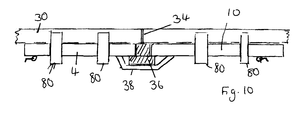
- Lugs 80 could be provided in the clamping surface of the work surface, as best illustrated in Fig. 10 which can hold a particularly wide workpiece over the top of the work surface, this extends the potential clamping width and a rough piece of wood 36 can be placed in gap 24 to provide additional support for the cut.
Landscapes
- Life Sciences & Earth Sciences (AREA)
- Engineering & Computer Science (AREA)
- Mechanical Engineering (AREA)
- Wood Science & Technology (AREA)
- Forests & Forestry (AREA)
- Sawing (AREA)
Applications Claiming Priority (4)
| Application Number | Priority Date | Filing Date | Title |
|---|---|---|---|
| GB9824111A GB2343407A (en) | 1998-11-04 | 1998-11-04 | Sawbench |
| GB9825500 | 1998-11-18 | ||
| GBGB9825500.3A GB9825500D0 (en) | 1998-11-18 | 1998-11-18 | Mitre guide |
| GB9824111 | 1999-11-04 |
Publications (2)
| Publication Number | Publication Date |
|---|---|
| EP1000716A2 true EP1000716A2 (de) | 2000-05-17 |
| EP1000716A3 EP1000716A3 (de) | 2004-01-07 |
Family
ID=26314610
Family Applications (1)
| Application Number | Title | Priority Date | Filing Date |
|---|---|---|---|
| EP19990308767 Withdrawn EP1000716A3 (de) | 1998-11-04 | 1999-11-04 | Werkbank speziell geeignet für verwendung als sägebock |
Country Status (2)
| Country | Link |
|---|---|
| US (1) | US6286405B1 (de) |
| EP (1) | EP1000716A3 (de) |
Cited By (1)
| Publication number | Priority date | Publication date | Assignee | Title |
|---|---|---|---|---|
| CN115351267A (zh) * | 2022-08-19 | 2022-11-18 | 重庆市铜梁区渝良铸造有限公司 | 一种精密铸造组树的分割装置 |
Families Citing this family (6)
| Publication number | Priority date | Publication date | Assignee | Title |
|---|---|---|---|---|
| US7059231B2 (en) * | 2003-05-19 | 2006-06-13 | Neil John Graham | Dental model cutter |
| US20040231750A1 (en) * | 2003-05-19 | 2004-11-25 | Vancleave Arnold A. | Laminate sheet seaming system |
| US7931058B2 (en) * | 2008-07-09 | 2011-04-26 | Felix Cruz | Flexible work table to miter and cut materials |
| USD667034S1 (en) | 2010-09-16 | 2012-09-11 | Woodworker's Supply, Inc. | No-mar workpiece support |
| US8336868B2 (en) * | 2010-09-16 | 2012-12-25 | Woodworker's Supply, Inc. | No-mar workpiece support |
| US8714498B2 (en) | 2011-02-08 | 2014-05-06 | Ip Holdings, Llc | Tray stand |
Family Cites Families (9)
| Publication number | Priority date | Publication date | Assignee | Title |
|---|---|---|---|---|
| GB2329147B (en) * | 1970-01-15 | 1999-11-17 | Huang Lung Lin | Device for supporting a saw |
| IT1054874B (it) * | 1976-02-19 | 1981-11-30 | Star Utensili Elett | Banco di lavoro ripiegabile |
| US4154435A (en) * | 1978-02-22 | 1979-05-15 | The Black And Decker Manufacturing Company | Portable workbench |
| US4527786A (en) * | 1982-07-30 | 1985-07-09 | Hsu Wen C | Workbench |
| US4648585A (en) * | 1985-06-07 | 1987-03-10 | Yang Tai Her | Vise structure having articulatable vise jaws |
| DE3667762D1 (de) * | 1985-08-19 | 1990-02-01 | Yang Tai Her | Werkbank und klemmvorrichtung fuer ein werkbankoberteil. |
| US4909491A (en) * | 1989-02-08 | 1990-03-20 | Cheng Wen H | Saw platform and workbench |
| EP0853530A1 (de) * | 1995-09-25 | 1998-07-22 | KENT, Frank Michael John | Mehrzweck werktischsystem |
| US5862731A (en) * | 1997-07-30 | 1999-01-26 | Chen; Fu-Yuan | Multifunctional workbench for woodworking |
-
1999
- 1999-11-04 US US09/433,203 patent/US6286405B1/en not_active Expired - Fee Related
- 1999-11-04 EP EP19990308767 patent/EP1000716A3/de not_active Withdrawn
Cited By (1)
| Publication number | Priority date | Publication date | Assignee | Title |
|---|---|---|---|---|
| CN115351267A (zh) * | 2022-08-19 | 2022-11-18 | 重庆市铜梁区渝良铸造有限公司 | 一种精密铸造组树的分割装置 |
Also Published As
| Publication number | Publication date |
|---|---|
| EP1000716A3 (de) | 2004-01-07 |
| US6286405B1 (en) | 2001-09-11 |
Similar Documents
| Publication | Publication Date | Title |
|---|---|---|
| US7140286B2 (en) | Dual adjustable feather jig | |
| US5730434A (en) | Clamping devices for compound miter saws | |
| EP0142368A2 (de) | Werkstückträger für eine Werkzeugmaschine | |
| US5273090A (en) | Wood working assembly | |
| US5421384A (en) | Unlimited width dovetailing system with overhead clamp | |
| US4291869A (en) | Workbench | |
| US20080053284A1 (en) | Sawing apparatus and saw fence system | |
| US5394781A (en) | Support structure and guide | |
| JPS6232077B2 (de) | ||
| EP3703912B1 (de) | Stützzusatzeinrichtung für eine werkstückauflageeinrichtung | |
| US4109900A (en) | Chainsaw vise | |
| US6990882B2 (en) | Device for precision cuts on aluminum and vinyl siding and other construction materials | |
| US5176058A (en) | Workpiece fixture | |
| EP0685284A1 (de) | Sägetisch mit Werkstückspannvorrichtung | |
| US6286405B1 (en) | Workbench | |
| US6708593B1 (en) | Folding, straight-line, workpiece guide for a band saw | |
| DE20203938U1 (de) | Bearbeitungsmaschine zum wenigstens teilweisen konturenabhängigen Ausschneiden oder Fräsen | |
| US5385183A (en) | Tool for producing straight edge | |
| US6868612B2 (en) | Cutting guide device for circular saws | |
| US20040074098A1 (en) | Cabinet scraper with handles | |
| CA1264336A (en) | Workholder for machine tools | |
| DE20107745U1 (de) | Schneidevorrichtung für plattenförmige Werkstücke | |
| US4889330A (en) | Trowel vise | |
| US20070107806A1 (en) | Ezee-feed | |
| US7377200B2 (en) | Workpiece holding devices for use with saws |
Legal Events
| Date | Code | Title | Description |
|---|---|---|---|
| PUAI | Public reference made under article 153(3) epc to a published international application that has entered the european phase |
Free format text: ORIGINAL CODE: 0009012 |
|
| AK | Designated contracting states |
Kind code of ref document: A2 Designated state(s): AT BE CH CY DE DK ES FI FR GB GR IE IT LI LU MC NL PT SE |
|
| AX | Request for extension of the european patent |
Free format text: AL;LT;LV;MK;RO;SI |
|
| 111L | Licence recorded |
Free format text: 20020705 0100 TEST-RITE INTERNATIONAL (U.K.) LIMITED |
|
| RAP1 | Party data changed (applicant data changed or rights of an application transferred) |
Owner name: TRABILIS LIMITED |
|
| REG | Reference to a national code |
Ref country code: DE Ref legal event code: 8566 |
|
| PUAL | Search report despatched |
Free format text: ORIGINAL CODE: 0009013 |
|
| AK | Designated contracting states |
Kind code of ref document: A3 Designated state(s): AT BE CH CY DE DK ES FI FR GB GR IE IT LI LU MC NL PT SE |
|
| AX | Request for extension of the european patent |
Extension state: AL LT LV MK RO SI |
|
| RIC1 | Information provided on ipc code assigned before grant |
Ipc: 7B 25H 1/10 B Ipc: 7B 25H 1/14 B Ipc: 7B 27B 21/00 A |
|
| AKX | Designation fees paid | ||
| STAA | Information on the status of an ep patent application or granted ep patent |
Free format text: STATUS: THE APPLICATION IS DEEMED TO BE WITHDRAWN |
|
| 18D | Application deemed to be withdrawn |
Effective date: 20040708 |