EP1000730A1 - Spritzgiessvorrichtung - Google Patents
Spritzgiessvorrichtung Download PDFInfo
- Publication number
- EP1000730A1 EP1000730A1 EP99122007A EP99122007A EP1000730A1 EP 1000730 A1 EP1000730 A1 EP 1000730A1 EP 99122007 A EP99122007 A EP 99122007A EP 99122007 A EP99122007 A EP 99122007A EP 1000730 A1 EP1000730 A1 EP 1000730A1
- Authority
- EP
- European Patent Office
- Prior art keywords
- screw
- pulley
- synchronization
- disposed
- support
- Prior art date
- Legal status (The legal status is an assumption and is not a legal conclusion. Google has not performed a legal analysis and makes no representation as to the accuracy of the status listed.)
- Granted
Links
Images


Classifications
-
- B—PERFORMING OPERATIONS; TRANSPORTING
- B29—WORKING OF PLASTICS; WORKING OF SUBSTANCES IN A PLASTIC STATE IN GENERAL
- B29C—SHAPING OR JOINING OF PLASTICS; SHAPING OF MATERIAL IN A PLASTIC STATE, NOT OTHERWISE PROVIDED FOR; AFTER-TREATMENT OF THE SHAPED PRODUCTS, e.g. REPAIRING
- B29C45/00—Injection moulding, i.e. forcing the required volume of moulding material through a nozzle into a closed mould; Apparatus therefor
- B29C45/03—Injection moulding apparatus
-
- B—PERFORMING OPERATIONS; TRANSPORTING
- B29—WORKING OF PLASTICS; WORKING OF SUBSTANCES IN A PLASTIC STATE IN GENERAL
- B29C—SHAPING OR JOINING OF PLASTICS; SHAPING OF MATERIAL IN A PLASTIC STATE, NOT OTHERWISE PROVIDED FOR; AFTER-TREATMENT OF THE SHAPED PRODUCTS, e.g. REPAIRING
- B29C45/00—Injection moulding, i.e. forcing the required volume of moulding material through a nozzle into a closed mould; Apparatus therefor
- B29C45/17—Component parts, details or accessories; Auxiliary operations
- B29C45/46—Means for plasticising or homogenising the moulding material or forcing it into the mould
- B29C45/47—Means for plasticising or homogenising the moulding material or forcing it into the mould using screws
- B29C45/50—Axially movable screw
- B29C45/5008—Drive means therefor
-
- B—PERFORMING OPERATIONS; TRANSPORTING
- B29—WORKING OF PLASTICS; WORKING OF SUBSTANCES IN A PLASTIC STATE IN GENERAL
- B29C—SHAPING OR JOINING OF PLASTICS; SHAPING OF MATERIAL IN A PLASTIC STATE, NOT OTHERWISE PROVIDED FOR; AFTER-TREATMENT OF THE SHAPED PRODUCTS, e.g. REPAIRING
- B29C45/00—Injection moulding, i.e. forcing the required volume of moulding material through a nozzle into a closed mould; Apparatus therefor
- B29C45/17—Component parts, details or accessories; Auxiliary operations
- B29C45/46—Means for plasticising or homogenising the moulding material or forcing it into the mould
- B29C45/47—Means for plasticising or homogenising the moulding material or forcing it into the mould using screws
- B29C45/50—Axially movable screw
- B29C45/5008—Drive means therefor
- B29C2045/5056—Drive means therefor screws axially driven by a rotatable screw shaft cooperating with a fixed nut
Definitions
- the present invention relates to an injection apparatus.
- the injection molding machine includes a mold clamping apparatus and an injection apparatus.
- the mold clamping apparatus is provided with a stationary platen and a movable platen.
- the movable platen is advanced and retracted by a mold clamping cylinder, to thereby perform mold closing, mold clamping, and mold opening.
- the injection apparatus includes a heating cylinder for heating and melting resin supplied from a hopper, and an injection nozzle for injecting the molten resin. Further, a screw is disposed within the heating cylinder such that the screw can be rotated and can be advanced and retracted. When the screw is advanced by a drive section disposed at the rear end of the screw, the resin is injected from the injection nozzle, and when the screw is retracted by the drive section, the resin is metered.
- the drive section comprises a front plate for supporting the heating cylinder; a rear plate disposed a predetermined distance away from the front plate; guide bars disposed between and supported by the front plate and the rear plate; and a movable plate disposed to be slidable along the guide bars.
- the above-described screw is rotatably supported by the movable plate.
- a ball screw shaft and a ball nut are disposed between the front plate and the movable plate.
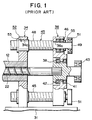
- FIG. 1 is a fragmentary sectional view of a drive section of a conventional injection apparatus
- FIG. 2 is a side view of the drive section of the conventional injection apparatus
- FIG. 3 is a schematic diagram showing the concept of the drive section of the conventional injection apparatus.
- reference numeral 12 denotes a heating cylinder
- 22 denotes a screw
- 31 denotes a slide table slidably disposed on an unillustrated frame
- 34 denotes a stationary plate fixed to the slide table 31.
- the rear end (right end in FIG. 1) of the heating cylinder 12 is fixed to the stationary plate 34.
- a movable plate 36 is disposed such that the movable plate 36 can be advanced and retracted relative to the stationary plate 34.
- a screw support shaft 38 is disposed at the approximate center of the movable plate 36 and is rotatably supported thereby via bearings 41 and 42.
- the rear end of the screw 22 is fixed to the screw support shaft 38, and a driven pulley 43 is fixed to the rear end of the screw support shaft 38.
- An unillustrated metering motor is attached to one side surface S1 of the movable plate 36, and an unillustrated drive pulley is attached to the output shaft of the metering motor.
- An unillustrated timing belt extends between and is wound, under tension, around the drive pulley and the driven pulley 43.
- the bearing 42 assumes the form of a thrust bearing in order to bear injection force that acts on the screw 22 upon injection.
- Parallel ball screw shafts 45 are disposed at a plurality of positions, for example, at two positions in the vicinity of the circumferential edge of the movable plate 36 and are rotatably supported by the movable plate 36 via bearings 46.
- Each of the ball screw shafts 45 has a screw portion 48 and a shaft portion 49 projecting from the rear end (right end in FIG. 1) of the screw portion 48.
- the shaft portion 49 penetrates a hole 36a formed in the movable plate 36 and extends rearward (rightward in FIG. 1), and a driven pulley 51 is attached to the rear end of the shaft portion 49.
- the screw portion 48 penetrates a hole 34a formed in the stationary plate 34 and extends forward (leftward in FIG.
- the ball nut 52 has a flange portion 53 at its front end (left end in FIG. 1) and is fixed to the stationary plate 34 by use of unillustrated bolts that penetrate the flange portion 53.
- Reference numeral 55 denotes a press plate for pressing the bearing 46.
- An injection motor 75 is attached to the approximate center of the other side surface S2 of the movable plate 36.
- a drive pulley 76 is attached to the output shaft 75a of the injection motor 75, and a timing belt 77 extends between and is wound, under tension, around the drive pulley 76 and the driven pulley 51.
- An unillustrated heater is disposed to surround the heating cylinder 12 and is adapted to heat the heating cylinder 12 to thereby melt the resin within the heating cylinder 12. Therefore, when the screw 22 is retracted by a predetermined amount, while being rotated, molten resin for one shot is accumulated on the front side of an unillustrated screw head.
- ⁇ 1 represents an effective angle of engagement of the drive pulley 76 which establishes meshing engagement for transmitting rotation from the injection motor 75 to the timing belt 77
- ⁇ 2 and ⁇ 3 respectively represent effective angles of engagement of the driven pulleys 51 which establish meshing engagements for transmitting rotation from the timing belt 77 to the respective ball screw shafts 45
- the inter-axis distance L1 between the drive pulley 76 and the driven pulleys 51 or the widths of the driven pulleys 51, the drive pulley 76, and the timing belt 77 may be increased in order to increase the drive-side effective angle ⁇ 1.
- the size of the injection apparatus increases, because the width of the movable plate 36 or the depth of the drive section must be increased.
- the widths of the driven pulleys 51, the drive pulley 76, and the timing belt 77 are increased, noise generated when the injection motor 75 is driven at high speed increases.
- An injection apparatus which comprises a cylinder section; a stationary plate fixed to a rear end of said cylinder section; a movable plate movable relative to said stationary plate; an injection member disposed within said cylinder section such that said injection member can be advanced and retracted, a rear end of said injection member being rotatably supported by said movable plate; drive means for generating a rotation; a plurality of conversion means each disposed between said stationary plate and said movable plate and adapted to covert a rotational force to a thrust force; transmission means disposed between said drive means and only a first conversion means of said plurality of conversion means for transmitting the rotation generated by said drive means to said first conversion means; and synchronization means for synchronizing rotation of said first conversion means with rotation of the remaining conversion means.
- An injection apparatus which comprises an injection apparatus comprising a first support; a second support, moveable relative to said first support; a cylinder fixed to said first support; a screw, rotatably connected to said second support, disposed within said cylinder; at least first and second ball and screw mechanisms connecting said first support to said second support, operable to move said second support relative to said first support; a motor having a rotatable output shaft; a first transmission transmitting a rotation of the output shaft of the motor to only said first ball and screw mechanism; and a second transmission transmitting a rotation of the first ball and screw mechanism to at least said second ball and screw mechanism.
- a method of operating an injection apparatus including a cylinder fixed to a first support and a metering screw rotatably connected to a second support and disposed within said cylinder is provided, comprising rotating a driving pulley with a motor; rotating a first screw through a belt connection from said driving pulley to a driven pulley fixed to said first screw; rotating at least a second screw through a transmission connected between said first screw and said second screw; and moving said first support relative to said second support via forces exerted by said first and second screws respectively on first and second nuts disposed about said first and second screws.
- FIG. 4 is a fragmentary sectional view of a drive section of an injection apparatus according to an embodiment of the present invention
- FIG. 5 is a sectional view of a main portion of the injection apparatus according to the embodiment of the present invention
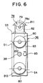
- FIG. 6 is a side view of the drive section of the injection apparatus according to the embodiment of the present invention.
- reference numeral 12 denotes a heating cylinder serving as the cylinder section, and an injection nozzle 12a is attached to the front end (left end in FIG. 5) of the heating cylinder 12.
- a screw 22 serving as the injection member is disposed within the heating cylinder 12 such that the screw 22 can be rotated and can be advanced and retracted.
- the screw 22 has a screw head 22a at its front end, and extends rearward (rightward in FIG. 5) within the heating cylinder 12.
- the rear end (right end in FIG. 5) of the screw 22 is connected to a drive section, which will be described later.
- a spiral flight 23 is formed on the peripheral surface of the screw 22, thereby forming a groove 26.
- a resin supply port 29 is formed at a predetermined position on the heating cylinder 12, and a hopper 30 is fixed to the resin supply port 29.
- resin 33 accommodated within the hopper 30 can be supplied to the resin supply port 29.
- the resin supply port 29 is formed at a position such that the resin supply port 29 faces the rear end portion (right-side end in FIG. 5) of the groove 26 when the screw 22 is positioned at a foremost position (leftward in FIG. 5) within the heating cylinder 12.
- reference numeral 12 denotes the heating cylinder
- 22 denotes the screw
- 31 denotes a slide table slidably disposed on an unillustrated frame
- 34 denotes a stationary plate fixed to the slide table 31.
- the rear end (right end in FIG. 4) of the heating cylinder 12 is fixed to the stationary plate 34.
- a movable plate 36 is disposed such that the movable plate 36 can be advanced and retracted relative to the stationary plate 34.
- a screw support shaft 38 is disposed at the approximate center of the movable plate 36 and is rotatably supported thereby via bearings 41 and 42.
- the rear end of the screw 22 is fixed to the screw support shaft 38, and an unillustrated driven pulley is fixed to the rear end of the screw support shaft 38.
- the bearing 42 assumes the form of a thrust bearing in order to bear injection force that acts on the screw 22 upon injection.
- An unillustrated metering motor serving as the first drive means is attached to one side surface S1 of the movable plate 36, and an unillustrated drive pulley is attached to the output shaft of the metering motor.
- a timing belt extends between and is wound, under tension, around the drive pulley and the driven pulley.
- Each of the drive pulley, the driven pulley, and the timing belt is of a toothed type.
- Parallel ball screw shafts 45 are disposed at a plurality of positions, for example, at two positions in the vicinity of the circumferential edge of the movable plate 36 and are rotatably supported by the movable plate 36 via bearings 46.
- Each of the ball screw shafts 45 has a screw portion 48 and a shaft portion 49 projecting from the rear end (right end in FIG. 4) of the screw portion 48.
- the shaft portion 49 penetrates a hole 36a formed in the movable plate 36 and extends rearward (rightward in FIG. 4), and a synchronization pulley 80 is attached to the rear end of the shaft portion 49.
- a driven pulley 81 is attached to the front end (left end in FIG. 4) of the shaft portion 49.
- Reference numeral 55 denotes a press plate for pressing the bearing 46.
- each ball screw shaft 45 penetrates a hole 34a formed in the stationary plate 34 and extends forward (leftward in FIG. 4) to be screw-engaged with a ball nut 52 attached to the stationary plate 34.
- the ball nut 52 has a flange portion 53 at its front end (left end in FIG. 4) and is fixed to the stationary plate 34 by use of unillustrated bolts that penetrate the flange portion 53.
- a ball screw composed of the ball screw shaft 45 and the ball nut 52 serving as the conversion means is disposed between the stationary plate 34 and the movable plate 36 and is adapted to covert rotational force to thrust force.
- An injection motor 78 serving as the second drive means is attached to the top surface S3 of the movable plate 36.
- a drive pulley 79 is attached to the output shaft 78a of the injection motor 78, and a timing belt 82 extends between and is wound, under tension, around the drive pulley 79 and the driven pulley 81.
- the drive pulley 79, the driven pulley 81, and the timing belt 82 constitute the transmission means.
- a tension roller 85 is rotatably disposed on the rear end surface S4 of the movable plate 36, and a timing belt 83 extends between and is wound, under tension, around the synchronization pulley 80 and the tension roller 85.
- the tension roller 85 is movably disposed, and tension is applied to the timing belt 83 in the direction of an arrow in FIG. 6.
- the tension roller 85 is disposed on the back-face-side of the timing belt 83 in order to apply tension to the timing belt 83 in the direction indicated by the arrow.
- a tension roller may be disposed on the front-face-side of the timing belt 83 in order to apply tension to the timing belt 83 in the direction opposite that indicated by the arrow.
- a toothed tension roller is not used for the tension roller 85.
- the synchronization pulley 80, the timing belt 83, and the tension roller 85 constitute the synchronization means for synchronizing rotation of one ball screw with rotation of the remaining ball screw(s).
- Each of the drive pulley 79, the synchronization pulley 80, the driven pulley 81, the timing belts 82 and 83, and the tension roller 85 is of a toothed type.
- An unillustrated heater is disposed to surround the heating cylinder 12 and is adapted to heat the heating cylinder 12 to thereby melt the resin 33 within the heating cylinder 12. Therefore, when the screw 22 is retracted by a predetermined amount, while being rotated, the molten resin 33, in an amount required for one shot, is accumulated on the front side of the screw head 22a.
- the injection motor 78 is driven.
- the rotation of the injection motor 78 is transmitted to each of the ball screw shafts 45 via the drive pulley 79, the timing belt 82, and the driven pulley 81.
- the rotations transmitted to the respective ball screw shafts 45 are synchronized with each other via the timing belt 83 and the synchronization pulleys 80.
- the timing belt 82 in order to rotate the two ball screw shafts 45 through driving of the single injection motor 78, the timing belt 82 extends between and is wound around the drive pulley 79 and the driven pulley 81, and the timing belt 83 extends between and is wound around the synchronization pulleys 80 and the tension roller 85. Therefore, each of the timing belts 82 and 83 travels along a track of a substantially oval shape.
- an effective angle ⁇ 11 of the drive pulley 79 which contributes to transmission of rotation from the injection motor 78 to the timing belt 82 is 180° or approximately 180 °
- an effective angle ⁇ 12 of the driven pulley 81 which contributes to transmission of rotation from the timing belt 82 to the corresponding ball screw shaft 45 is 180° or approximately 180 ° .
- each synchronization pulley 80 which contributes to synchronization of rotation transmitted from the shaft portion 49 becomes approximately 180 ° .
- the rotation transmitted from the injection motor 78 can be reliably transmitted to the timing belt 83, and the rotations transmitted to the respective synchronization pulleys 80 can be synchronized in a reliable manner.
- the rotation can be transmitted to the ball screw shafts 45 in a stabilized manner, so that the performance of the injection apparatus can be improved.
- the size of the injection apparatus can be decreased.
- the drive pulley 79, the driven pulley 81, and the timing belt 82 are disposed independent of the synchronization pulleys 80 and the timing belt 83, the specifications of the drive pulley 79, the driven pulley 81, and the timing belt 82 can be set to differ from those of the synchronization pulleys 80 and the timing belt 83. Therefore, the size of, for example, the driven pulley 81 can be decreased, and the corresponding inertia can be decreased.
- the synchronization means is constituted by the synchronization pulleys 80, the timing belt 83, and the tension roller 85.
- the synchronization means may be constituted by a gear mechanism.
- a synchronization gear is attached to the rear end of each shaft portion 49, and an idle gear is disposed between the synchronization gears in order to transmit rotation.
- the idle gear is disposed such that all of the synchronization gears rotate in the same direction.
- the invention relates to an injection apparatus comprising: a cylinder section; a stationary plate; a movable plate movable relative to said stationary plate; an injection member disposed within said cylinder section; drive means for generating a rotation; and conversion means.
Landscapes
- Engineering & Computer Science (AREA)
- Manufacturing & Machinery (AREA)
- Mechanical Engineering (AREA)
- Injection Moulding Of Plastics Or The Like (AREA)
- Materials For Medical Uses (AREA)
Applications Claiming Priority (2)
| Application Number | Priority Date | Filing Date | Title |
|---|---|---|---|
| JP32387198 | 1998-11-13 | ||
| JP32387198A JP3316190B2 (ja) | 1998-11-13 | 1998-11-13 | 射出装置 |
Publications (2)
| Publication Number | Publication Date |
|---|---|
| EP1000730A1 true EP1000730A1 (de) | 2000-05-17 |
| EP1000730B1 EP1000730B1 (de) | 2003-08-06 |
Family
ID=18159535
Family Applications (1)
| Application Number | Title | Priority Date | Filing Date |
|---|---|---|---|
| EP99122007A Expired - Lifetime EP1000730B1 (de) | 1998-11-13 | 1999-11-11 | Spritzgiessvorrichtung |
Country Status (9)
| Country | Link |
|---|---|
| US (1) | US6409957B1 (de) |
| EP (1) | EP1000730B1 (de) |
| JP (1) | JP3316190B2 (de) |
| KR (1) | KR100355742B1 (de) |
| CN (1) | CN1086337C (de) |
| AT (1) | ATE246584T1 (de) |
| DE (1) | DE69910144T2 (de) |
| SG (1) | SG80659A1 (de) |
| TW (1) | TW467819B (de) |
Cited By (2)
| Publication number | Priority date | Publication date | Assignee | Title |
|---|---|---|---|---|
| EP1231043A1 (de) * | 2001-02-08 | 2002-08-14 | Negri Bossi S.P.A. | Spritzgiessanordnung für Spritzgiessmaschinen für Kunststoff |
| EP2374597A1 (de) * | 2010-04-09 | 2011-10-12 | Wittmann Battenfeld GmbH | Einspritzeinheit einer Spritzgiessmaschine |
Families Citing this family (6)
| Publication number | Priority date | Publication date | Assignee | Title |
|---|---|---|---|---|
| JP4059892B2 (ja) * | 2005-07-06 | 2008-03-12 | ファナック株式会社 | 射出成形機の射出装置 |
| CN102642283A (zh) * | 2011-12-12 | 2012-08-22 | 宁波长飞亚塑料机械制造有限公司 | 注塑机注射装置的双丝杠同步驱动装置 |
| CN106612032A (zh) * | 2015-10-21 | 2017-05-03 | 王心成 | 一种多轴齿轮减速大载荷伺服动力头及使用方法 |
| JP6339648B2 (ja) * | 2016-11-22 | 2018-06-06 | ファナック株式会社 | 射出装置および軸芯位置調整方法 |
| JP6457572B2 (ja) * | 2017-03-13 | 2019-01-23 | ファナック株式会社 | 射出装置 |
| CN108773036A (zh) * | 2018-06-27 | 2018-11-09 | 东华机械有限公司 | 双丝杆注射的电动射台机构 |
Citations (4)
| Publication number | Priority date | Publication date | Assignee | Title |
|---|---|---|---|---|
| EP0188622A1 (de) * | 1984-07-07 | 1986-07-30 | Fanuc Ltd. | Einspritzmechanismus mit drehender schraube für einspritzgiessvorrichtung |
| EP0247208A1 (de) * | 1985-11-30 | 1987-12-02 | Fanuc Ltd. | Antriebsvorrichtung für spritzgiessmaschine |
| EP0427866A1 (de) * | 1989-05-24 | 1991-05-22 | Fanuc Ltd. | Spritzgiessvorrichtung vom typ mit zwei platten |
| EP0627289A1 (de) * | 1993-05-29 | 1994-12-07 | Karl Hehl | Spritzgiesseinheit für eine Kunststoff-Spritzgiessmaschine |
Family Cites Families (1)
| Publication number | Priority date | Publication date | Assignee | Title |
|---|---|---|---|---|
| JPS60174623A (ja) * | 1984-02-21 | 1985-09-07 | Toshiba Mach Co Ltd | 射出成形機 |
-
1998
- 1998-11-13 JP JP32387198A patent/JP3316190B2/ja not_active Expired - Fee Related
-
1999
- 1999-10-22 TW TW088118287A patent/TW467819B/zh not_active IP Right Cessation
- 1999-10-26 SG SG9905336A patent/SG80659A1/en unknown
- 1999-10-29 KR KR1019990047428A patent/KR100355742B1/ko not_active Expired - Fee Related
- 1999-11-01 CN CN99122185A patent/CN1086337C/zh not_active Expired - Fee Related
- 1999-11-08 US US09/435,858 patent/US6409957B1/en not_active Expired - Fee Related
- 1999-11-11 DE DE69910144T patent/DE69910144T2/de not_active Expired - Lifetime
- 1999-11-11 EP EP99122007A patent/EP1000730B1/de not_active Expired - Lifetime
- 1999-11-11 AT AT99122007T patent/ATE246584T1/de not_active IP Right Cessation
Patent Citations (4)
| Publication number | Priority date | Publication date | Assignee | Title |
|---|---|---|---|---|
| EP0188622A1 (de) * | 1984-07-07 | 1986-07-30 | Fanuc Ltd. | Einspritzmechanismus mit drehender schraube für einspritzgiessvorrichtung |
| EP0247208A1 (de) * | 1985-11-30 | 1987-12-02 | Fanuc Ltd. | Antriebsvorrichtung für spritzgiessmaschine |
| EP0427866A1 (de) * | 1989-05-24 | 1991-05-22 | Fanuc Ltd. | Spritzgiessvorrichtung vom typ mit zwei platten |
| EP0627289A1 (de) * | 1993-05-29 | 1994-12-07 | Karl Hehl | Spritzgiesseinheit für eine Kunststoff-Spritzgiessmaschine |
Cited By (3)
| Publication number | Priority date | Publication date | Assignee | Title |
|---|---|---|---|---|
| EP1231043A1 (de) * | 2001-02-08 | 2002-08-14 | Negri Bossi S.P.A. | Spritzgiessanordnung für Spritzgiessmaschinen für Kunststoff |
| US6682338B2 (en) | 2001-02-08 | 2004-01-27 | Negri Bossi S.P.A. | Injection assembly for injection moulding machines for plastics material |
| EP2374597A1 (de) * | 2010-04-09 | 2011-10-12 | Wittmann Battenfeld GmbH | Einspritzeinheit einer Spritzgiessmaschine |
Also Published As
| Publication number | Publication date |
|---|---|
| TW467819B (en) | 2001-12-11 |
| SG80659A1 (en) | 2001-05-22 |
| DE69910144T2 (de) | 2004-06-09 |
| CN1253874A (zh) | 2000-05-24 |
| KR20000035109A (ko) | 2000-06-26 |
| KR100355742B1 (ko) | 2002-10-19 |
| JP3316190B2 (ja) | 2002-08-19 |
| DE69910144D1 (de) | 2003-09-11 |
| ATE246584T1 (de) | 2003-08-15 |
| CN1086337C (zh) | 2002-06-19 |
| JP2000141438A (ja) | 2000-05-23 |
| US6409957B1 (en) | 2002-06-25 |
| EP1000730B1 (de) | 2003-08-06 |
Similar Documents
| Publication | Publication Date | Title |
|---|---|---|
| EP0723848B1 (de) | Spritzvorrichtung für eine elektrische Spritzgiessmaschine | |
| JP3321766B2 (ja) | 射出成形機の射出装置 | |
| US6364650B1 (en) | Injection apparatus with load detection between support members | |
| JP3321452B2 (ja) | 電動射出成形機 | |
| EP1000730A1 (de) | Spritzgiessvorrichtung | |
| US7261554B2 (en) | Injection unit of injection molding machine | |
| EP1674233A1 (de) | Elektrische spritzgiessvorrichtung und diese verwendendes spritzgiessverfahren | |
| US6059556A (en) | Injection apparatus for injection molding machine | |
| US6015284A (en) | Injection unit for injection molding machines | |
| JP3496089B2 (ja) | 射出成形機の駆動装置 | |
| JP3336267B2 (ja) | 射出装置 | |
| JP4626870B2 (ja) | 射出成形機の駆動装置 | |
| JP2893477B2 (ja) | 竪型射出成形機の射出機構 | |
| JP2000246772A (ja) | 電動式射出成形機の射出装置 | |
| JP3130824B2 (ja) | エジェクタ装置 | |
| JP3878936B2 (ja) | 電動射出成形機の射出装置 | |
| JPH06106586A (ja) | 電動射出成形機の射出装置 | |
| JPH10235698A (ja) | 電動射出成形機 | |
| JP2001221304A (ja) | 動力伝達装置 | |
| JP2000176978A (ja) | 射出成形機の射出装置 | |
| JP3179757B2 (ja) | 射出装置 | |
| JP2952460B2 (ja) | 射出成形機におけるエジェクター装置 | |
| JPH11198197A (ja) | 電動式射出成形機のエジェクタ装置 | |
| JP2005178275A (ja) | 射出成形機 | |
| JP2004223745A (ja) | 射出装置及び射出方法 |
Legal Events
| Date | Code | Title | Description |
|---|---|---|---|
| PUAI | Public reference made under article 153(3) epc to a published international application that has entered the european phase |
Free format text: ORIGINAL CODE: 0009012 |
|
| AK | Designated contracting states |
Kind code of ref document: A1 Designated state(s): AT CH DE FR GB IT LI |
|
| AX | Request for extension of the european patent |
Free format text: AL;LT;LV;MK;RO;SI |
|
| 17P | Request for examination filed |
Effective date: 20001117 |
|
| AKX | Designation fees paid |
Free format text: AT CH DE FR GB IT LI |
|
| 17Q | First examination report despatched |
Effective date: 20010824 |
|
| GRAH | Despatch of communication of intention to grant a patent |
Free format text: ORIGINAL CODE: EPIDOS IGRA |
|
| GRAH | Despatch of communication of intention to grant a patent |
Free format text: ORIGINAL CODE: EPIDOS IGRA |
|
| GRAA | (expected) grant |
Free format text: ORIGINAL CODE: 0009210 |
|
| AK | Designated contracting states |
Designated state(s): AT CH DE FR GB IT LI |
|
| REG | Reference to a national code |
Ref country code: GB Ref legal event code: FG4D |
|
| REG | Reference to a national code |
Ref country code: CH Ref legal event code: EP |
|
| REF | Corresponds to: |
Ref document number: 69910144 Country of ref document: DE Date of ref document: 20030911 Kind code of ref document: P |
|
| REG | Reference to a national code |
Ref country code: CH Ref legal event code: NV Representative=s name: RIEDERER HASLER & PARTNER PATENTANWAELTE AG |
|
| ET | Fr: translation filed | ||
| PLBE | No opposition filed within time limit |
Free format text: ORIGINAL CODE: 0009261 |
|
| STAA | Information on the status of an ep patent application or granted ep patent |
Free format text: STATUS: NO OPPOSITION FILED WITHIN TIME LIMIT |
|
| 26N | No opposition filed |
Effective date: 20040507 |
|
| PGFP | Annual fee paid to national office [announced via postgrant information from national office to epo] |
Ref country code: FR Payment date: 20041109 Year of fee payment: 6 |
|
| PGFP | Annual fee paid to national office [announced via postgrant information from national office to epo] |
Ref country code: GB Payment date: 20041110 Year of fee payment: 6 |
|
| PG25 | Lapsed in a contracting state [announced via postgrant information from national office to epo] |
Ref country code: GB Free format text: LAPSE BECAUSE OF NON-PAYMENT OF DUE FEES Effective date: 20051111 |
|
| GBPC | Gb: european patent ceased through non-payment of renewal fee |
Effective date: 20051111 |
|
| PG25 | Lapsed in a contracting state [announced via postgrant information from national office to epo] |
Ref country code: FR Free format text: LAPSE BECAUSE OF NON-PAYMENT OF DUE FEES Effective date: 20060731 |
|
| REG | Reference to a national code |
Ref country code: FR Ref legal event code: ST Effective date: 20060731 |
|
| PGFP | Annual fee paid to national office [announced via postgrant information from national office to epo] |
Ref country code: CH Payment date: 20081117 Year of fee payment: 10 |
|
| PGFP | Annual fee paid to national office [announced via postgrant information from national office to epo] |
Ref country code: AT Payment date: 20081112 Year of fee payment: 10 |
|
| PGFP | Annual fee paid to national office [announced via postgrant information from national office to epo] |
Ref country code: IT Payment date: 20081126 Year of fee payment: 10 |
|
| REG | Reference to a national code |
Ref country code: CH Ref legal event code: PL |
|
| PG25 | Lapsed in a contracting state [announced via postgrant information from national office to epo] |
Ref country code: AT Free format text: LAPSE BECAUSE OF NON-PAYMENT OF DUE FEES Effective date: 20091111 |
|
| PG25 | Lapsed in a contracting state [announced via postgrant information from national office to epo] |
Ref country code: LI Free format text: LAPSE BECAUSE OF NON-PAYMENT OF DUE FEES Effective date: 20091130 Ref country code: CH Free format text: LAPSE BECAUSE OF NON-PAYMENT OF DUE FEES Effective date: 20091130 |
|
| PG25 | Lapsed in a contracting state [announced via postgrant information from national office to epo] |
Ref country code: IT Free format text: LAPSE BECAUSE OF NON-PAYMENT OF DUE FEES Effective date: 20091111 |
|
| PGFP | Annual fee paid to national office [announced via postgrant information from national office to epo] |
Ref country code: DE Payment date: 20131106 Year of fee payment: 15 |
|
| REG | Reference to a national code |
Ref country code: DE Ref legal event code: R119 Ref document number: 69910144 Country of ref document: DE |
|
| PG25 | Lapsed in a contracting state [announced via postgrant information from national office to epo] |
Ref country code: DE Free format text: LAPSE BECAUSE OF NON-PAYMENT OF DUE FEES Effective date: 20150602 |