EP1000735A2 - Dispositif de remplissage dans des presses axiales pour poudre - Google Patents
Dispositif de remplissage dans des presses axiales pour poudre Download PDFInfo
- Publication number
- EP1000735A2 EP1000735A2 EP99121951A EP99121951A EP1000735A2 EP 1000735 A2 EP1000735 A2 EP 1000735A2 EP 99121951 A EP99121951 A EP 99121951A EP 99121951 A EP99121951 A EP 99121951A EP 1000735 A2 EP1000735 A2 EP 1000735A2
- Authority
- EP
- European Patent Office
- Prior art keywords
- filler
- filling
- shoe
- filling device
- plate
- Prior art date
- Legal status (The legal status is an assumption and is not a legal conclusion. Google has not performed a legal analysis and makes no representation as to the accuracy of the status listed.)
- Granted
Links
- 239000000843 powder Substances 0.000 title claims abstract description 45
- 239000000945 filler Substances 0.000 claims abstract description 97
- 238000006073 displacement reaction Methods 0.000 claims 1
- 230000001105 regulatory effect Effects 0.000 claims 1
- 238000003825 pressing Methods 0.000 description 8
- 239000011159 matrix material Substances 0.000 description 6
- XEEYBQQBJWHFJM-UHFFFAOYSA-N Iron Chemical compound [Fe] XEEYBQQBJWHFJM-UHFFFAOYSA-N 0.000 description 5
- 238000000034 method Methods 0.000 description 5
- 238000003860 storage Methods 0.000 description 5
- 230000008878 coupling Effects 0.000 description 3
- 238000010168 coupling process Methods 0.000 description 3
- 238000005859 coupling reaction Methods 0.000 description 3
- 239000000969 carrier Substances 0.000 description 2
- 239000000919 ceramic Substances 0.000 description 2
- 230000009849 deactivation Effects 0.000 description 2
- 229910052742 iron Inorganic materials 0.000 description 2
- 230000007246 mechanism Effects 0.000 description 2
- 230000008569 process Effects 0.000 description 2
- 230000003213 activating effect Effects 0.000 description 1
- 230000004913 activation Effects 0.000 description 1
- 238000010276 construction Methods 0.000 description 1
- 230000001419 dependent effect Effects 0.000 description 1
- 238000009826 distribution Methods 0.000 description 1
- 230000000694 effects Effects 0.000 description 1
- 238000009434 installation Methods 0.000 description 1
- 230000007257 malfunction Effects 0.000 description 1
- 238000004519 manufacturing process Methods 0.000 description 1
- 239000000463 material Substances 0.000 description 1
- 230000000284 resting effect Effects 0.000 description 1
- 230000001360 synchronised effect Effects 0.000 description 1
- 238000011144 upstream manufacturing Methods 0.000 description 1
Images


Classifications
-
- B—PERFORMING OPERATIONS; TRANSPORTING
- B28—WORKING CEMENT, CLAY, OR STONE
- B28B—SHAPING CLAY OR OTHER CERAMIC COMPOSITIONS; SHAPING SLAG; SHAPING MIXTURES CONTAINING CEMENTITIOUS MATERIAL, e.g. PLASTER
- B28B13/00—Feeding the unshaped material to moulds or apparatus for producing shaped articles; Discharging shaped articles from such moulds or apparatus
- B28B13/02—Feeding the unshaped material to moulds or apparatus for producing shaped articles
- B28B13/0215—Feeding the moulding material in measured quantities from a container or silo
- B28B13/023—Feeding the moulding material in measured quantities from a container or silo by using a feed box transferring the moulding material from a hopper to the moulding cavities
-
- B—PERFORMING OPERATIONS; TRANSPORTING
- B30—PRESSES
- B30B—PRESSES IN GENERAL
- B30B15/00—Details of, or accessories for, presses; Auxiliary measures in connection with pressing
- B30B15/30—Feeding material to presses
- B30B15/302—Feeding material in particulate or plastic state to moulding presses
- B30B15/304—Feeding material in particulate or plastic state to moulding presses by using feed frames or shoes with relative movement with regard to the mould or moulds
-
- B—PERFORMING OPERATIONS; TRANSPORTING
- B22—CASTING; POWDER METALLURGY
- B22F—WORKING METALLIC POWDER; MANUFACTURE OF ARTICLES FROM METALLIC POWDER; MAKING METALLIC POWDER; APPARATUS OR DEVICES SPECIALLY ADAPTED FOR METALLIC POWDER
- B22F2998/00—Supplementary information concerning processes or compositions relating to powder metallurgy
Definitions
- the invention relates to a filling device for in particular axial powder presses according to the generic terms Features of claim 1.
- a filling device For filling a powder press with powder, in particular Ceramic and iron powder, is between each pressing process a filling device over the filler plate or Matrix plate opening of a filler plate or one therein recessed die plate of an adapter fill them with powder. Before pressing the powder the filling device in a rest position next to the press withdrawn.
- various adjustment mechanisms known, for example Crank or spindle drives whose drive z.
- the filling device comprises a filling shoe, which on a Filler main body of a filling drive is firmly attached and so that it can be moved back and forth on the filler plate slides. Introduces into a central opening of the filling shoe Filling tube into it, the one with the filling shoe and the filling drive is rigidly connected. At the end of the filling pipe that comes out of the Filling shoe protrudes, a hose is attached over which Powder is fed from a silo. The silo is in the Usually above the filling device and to the side of the press arranged.
- the filling shoe When filling the die with powder, the filling shoe must be over pushed the die plate opening in the die plate and firmly pressed onto it to ensure a safe, even and sufficient filling of the die to be able to guarantee.
- the contact pressure must also be large enough to prevent powder between the filling shoe and the filling plate.
- the required Pressure must be particularly high if the usually with heavy powder partially filled hose and the silo at Moving the filling device to be pivoted and on the filling shoe in particular one of the shift opposing force and tilting the filling shoe exercise.
- the disadvantage is that on the filler plate and the die and about this on the adapter of the press a not centric pressure from obliquely above or pull from obliquely acts below, causing malfunctions, wear and tear Mispressions can result.
- the devices complicated structure, difficult to adjust and have to be replaced almost completely regularly, as the Filling shoe is mostly made of plastic and at Pulling over the filler plate wears out quickly, especially if powder residues between get this.
- a filling device is known from DE 39 16 951 A1 a filling device with a filler main body, a Filling shoe and a powder feeder.
- the filling device is back and forth on a filler plate slidable.
- the purpose of this device is as possible easy adjustment of the position of the filler main body with the filling shoe opposite the position of a die.
- the filler main body is only one rod-shaped cantilever arm at the end of an elaborate mechanism educated.
- the filling shoe sits on the cantilever arm on the press side and can be pressed onto the filler plate in the filling position.
- the filling shoe is by means of horizontal joints pivoted in a bracket, which in turn the forms the front end of the cantilever arm.
- the object of the invention is a filling device to propose in particular for axial powder presses that have a simple structure and an even pressure of the filling shoe on the filler and / or die plate enable.
- the detachably adjustable The filler shoe can be coupled to the filler drive plate the filling shoe with an even pressure distribution on the Filler plate.
- Coupling the filling shoe to the filler drive plate via a frame enables a well controllable pressing of the filling shoe to the filler plate. Forces such. B. from that Filling hose when moving the filling device on this act, are no longer transferred to the filling shoe.
- Coupling the filler shoe via filler shoe bearing bolts overlapped by recesses in the underside of the frame are made easy with intermittent contact pressure and safely moving the filling shoe on top of the Filler plate.
- an optional less compressible pressure can act on the filling shoe, so that it is pressed firmly enough onto the filler plate to prevent powder residue from entering between the filling shoe and prevent filler plate.
- the filling shoe which is mostly made of plastic manufactured wear part for larger quantities of manufacturing green parts or compacts because of its Wear must be replaced frequently, quickly easy lifting of the frame from the filling device be taken and exchanged.
- the attachment of the powder feeder to the Filler drive plate via adjustable carrier enables one variable setting of the outlet openings of the filling pipes the die.
- the density of the filled powder, especially iron or ceramic powder, is with this Structure not only in the entire die but also in individual sections of this easily adjustable. Thereby can e.g. B. Matrices for making eccentric Sintered parts, e.g. B. for connecting rods, more specifically filled with powder become.
- the quick adjustment of the whole Can be applied to other compacts.
- a suitable filling shoe in the Filling device can be used.
- Filling tubes with different, also not circular Cross sections enable a targeted feed of powder or powder quantities in certain areas of the die.
- This Filling effect can be achieved by using adjustable flaps in the pipes to be adapted to special requirements.
- This and the use of several filling tubes side by side enables an optimized filling of the die. Thereby especially the filling pressure and the density adjustable.
- the setting of the individual component groups is general easier because the individual adjustment elements in the area of Filler drive plate easily accessible in front of the press are upstream.
- one comprises Powder press a press stand 1 on which a base plate 2 sits.
- the press stand 1 is above the base plate 2 guided at least one vertically adjustable adapter 3 arranged.
- the adapter has a jacket plate 4, one Matrix plate 5 and a filler plate 6, these three assembly elements 4 - 6 firmly connected are.
- the die plate 5 sits on the jacket plate 4.
- the filler plate 6 sits on or around the through it partially protruding die plate 5, the Surfaces around a die plate opening 5a form common flat sliding surface for a filling shoe 15.
- This assembly sits on the jacket plate, for example 4 a driver 7.
- a driver sits on the driver 7
- this is mounted on guide rails 9 which are on the side Press stand 1 attached in the vertical or longitudinal direction are.
- the actual filling device 10 On the carriage 11, in particular on its upper side the actual filling device 10 is arranged.
- In the structure shown is about each two hoses 13 and filling pipes 14 one to be pressed Powder fed into the filling shoe 15 of the filling device 12.
- the filling device 12 in particular its filling shoe 15, is slidable on the filler plate 6 and the die plate 5 stored.
- a conventional adjustment drive 16 thereby u. a. the filling shoe 15 synchronized with the press cycle of the Press over a die plate opening 5a in the Die plate 5 can be moved into the press to use the die Fill powder, or from the area of the press stand can be moved laterally outwards around what has been filled into the die To be able to press powder.
- the process can automated, especially computer controlled.
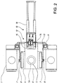
- the Filling device 12 a filler main body or a Filler drive plate 17, the one at the press end Piston rod 18 of the adjustment drive 16 is attached.
- the Filler drive plate 17 is preferably just above the Filler plate 6 guided back and forth so that it does not rub against each other.
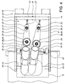
- the filler drive plate 17 On the top of the filler drive plate 17 are one or several elongated carriers 20 stored in the illustrated Embodiment two, each for holding and positioning a filling pipe 14 are formed. By doing adjusting drive end of the carrier 20 is in the In the longitudinal direction, an elongated hole 21 is formed through which a Carrier journal 22 is guided out of the top of the Filler drive plate 17 protrudes upwards.
- each carrier 20 and in the Elongated hole 21 guides a set screw 23 into it.
- the carrier journal 22 in the Elongated hole 21 can be adjusted and fixed in the longitudinal direction thereof, around the carrier 20 in its longitudinal direction and parallel to the To be able to adjust the surface of the filler drive plate 17.
- each carrier 20 leads transversely to its longitudinal direction and parallel to the surface of the filler drive plate 17 Threaded bore 24 into which another set screw 25 is screwed in.
- the shaft of this screw 25 leads to a stop 26 and lies against this, the Stop 26 on the top of the filler drive plate 17 sits.
- the carriers 20 are on the surface the filler drive plate 17 also laterally adjustable and fixable, the carrier journal 22 the pivot point of the Form carrier 20.
- Threaded bolt 28 from the top of the Filler drive plate 17 protrudes upwards.
- the Through hole 27 is dimensioned so that the 20th seated fill pipe 14 in any required position above the die plate opening 5a can be brought.
- the Threaded bolt 28 continues through a spring washer 29 and a clamping nut 30.
- the clamping washer 29 has such a large one Extent that they are in every carrier position on the edge of Through hole 27 rests on the top of the carrier 20.
- press-side end of the carrier 20 is in each case at least one fill pipe 14 attached.
- a filling tube 14 leads through the front, Press-side end of the carrier 20 and is fixed therein can be clamped.
- the filling tubes are used to increase throughput so inclined that, on the one hand, they run flat enough to accommodate a rapid pushing in and pulling out of the filling device 10 into and out of the press enable, and on the other hand steep enough to be a uniform and rapid flow of the material to be pressed Allow powder.
- each filling pipe 14 there is a hose 13 attached, the powder from a silo or one Dosing device feeds.
- the lower end of the fill tubes 14 is so inclined to the longitudinal direction that the Filler tube edges substantially parallel to the plane of the Matrix plate 5 and the filler plate 5 and the Matrix plate opening 5a and run closely above.
- the frame 40 for holding and guiding the filling shoe 15 stored.
- the frame 40 comprises two brackets 41 and 42 which preferably to the side of the filler drive plate 17 and in the longitudinal direction of which.
- the end sections of the filler or adjusting drive both brackets are via a square or transverse bracket 43 connected to each other, end face pin 44 of this are stored in holes in the bracket 41 or 42.
- the Crossbar 43 runs above the actuator end portion of the Filler drive plate 17 and somewhat spaced therefrom.
- the Crossbar 43 is on at least one press piece Piston rod 18 of a short-stroke cylinder 19 mounted.
- the Short stroke cylinder 19 is on or in the filler drive plate 17 attached and serves the crossbar 43 of the frame 40th to push upwards.
- the filler shoe bearing pin 45 has one each semicircular recess 46 in the underside of the bracket 41 or 42, d. H. by resting the recesses 46 in the Iron 41 and 42 on the filler shoe bearing pin 45 is the filling shoe after simply lifting the bracket 41 and 42 or the filling device 10 with these brackets very simple and quickly removable and replaceable.
- bracket 41 and 42 are the bracket 41 and 42 on the Side of the filler drive plate 17 in the middle or Press side section stored.
- For swiveling Storage of the bracket 41 and 42 is used from each Filler drive plate 17 laterally protruding bracket bearing pin 48.
- brackets 41 and 42 pivoted about the bracket bearing pin 48. This will make the Press-side ends of the bracket 41 and 42 down pivots and act on the filler shoe bearing bolts 45 corresponding to the pressure strength of the short-stroke cylinder 19 and Acting lever of the bracket 41 or 42.
- the short-stroke cylinder 19 can be filled into the press 10 partially or preferably continuously activated during operation his.
- the front or press side section of the brackets 41 and 42 is down in the illustrated embodiment wider than their section on the actuator side.
- another mounting of the frame 40 is also possible possible on the filler drive plate 17, e.g. B. a tour of flat brackets in a groove-like recess in their surface.
- An exemplary press cycle comprises the steps forward or Inserting the filling device 10 over the filler plate 6 in the press, so that the filling shoe 15 above the Die plate opening 5a lies, tight pressing of the Filling shoe 15 on the die plate 5 by activating the Short stroke cylinder 19, filling the die 5 with the press Powder, optional partial or complete deactivation of the short-stroke cylinder 19, withdraw the filling device 10 with the filling shoe 15 out of the press, eating the Powder in the die through to a pressed or green part Activation of the corresponding press ram and ultimately after pressing the deactivation and withdrawal of the Ram.
- the filling device 10 on the Carriage 11 is the entire filling device 10 when eating together with the adapter 3, d. H.
- the control or regulation of the individual Sequence steps are preferably carried out using a computer or a computer unit, which also measured values of pressure, distance and Accelerometers used on the system.
- Embodiment with independent inventive meaning have the filling tubes instead of a circular cross-section an elliptical cross section.
- this embodiment is also the installation of an adjustable flap in the Filling tubes possible to fine tune the To be able to make pipe cross-section.
- a preferred embodiment is the adjustment of the Folding possible by means of an external control a central computer to control the entire system is adjustable.
Landscapes
- Engineering & Computer Science (AREA)
- Mechanical Engineering (AREA)
- Manufacturing & Machinery (AREA)
- Chemical & Material Sciences (AREA)
- Ceramic Engineering (AREA)
- Powder Metallurgy (AREA)
- Basic Packing Technique (AREA)
- Devices And Processes Conducted In The Presence Of Fluids And Solid Particles (AREA)
- Processing And Handling Of Plastics And Other Materials For Molding In General (AREA)
Applications Claiming Priority (2)
| Application Number | Priority Date | Filing Date | Title |
|---|---|---|---|
| DE19851527 | 1998-11-09 | ||
| DE19851527A DE19851527A1 (de) | 1998-11-09 | 1998-11-09 | Füllvorrichtung für axiale Pulverpressen |
Publications (3)
| Publication Number | Publication Date |
|---|---|
| EP1000735A2 true EP1000735A2 (fr) | 2000-05-17 |
| EP1000735A3 EP1000735A3 (fr) | 2002-03-27 |
| EP1000735B1 EP1000735B1 (fr) | 2007-01-03 |
Family
ID=7887126
Family Applications (1)
| Application Number | Title | Priority Date | Filing Date |
|---|---|---|---|
| EP99121951A Expired - Lifetime EP1000735B1 (fr) | 1998-11-09 | 1999-11-09 | Dispositif de remplissage dans des presses axiales pour poudre |
Country Status (4)
| Country | Link |
|---|---|
| US (1) | US6343715B1 (fr) |
| EP (1) | EP1000735B1 (fr) |
| AT (1) | ATE350211T1 (fr) |
| DE (2) | DE19851527A1 (fr) |
Cited By (1)
| Publication number | Priority date | Publication date | Assignee | Title |
|---|---|---|---|---|
| DE102011118209A1 (de) | 2011-11-12 | 2013-05-16 | Dorst Technologies Gmbh & Co. Kg | Keramik- und/oder Metallpulverpresse mit einem Füllschuh und Füllleitungen und Verfahren zum Pressen eines Presskörpers in einer solchen Presse |
Families Citing this family (8)
| Publication number | Priority date | Publication date | Assignee | Title |
|---|---|---|---|---|
| DE10152114A1 (de) * | 2001-10-23 | 2003-04-30 | Dorst Masch & Anlagen | Pressenanordnung, insbesondere zum Pressen von keramischen Presslingen |
| US20070020579A1 (en) * | 2005-07-25 | 2007-01-25 | Michael Migdal | Tooth powdering device |
| DE102006023333B3 (de) | 2006-05-11 | 2007-11-22 | Korsch Ag | Tablettiermaschine |
| CA2669965A1 (fr) * | 2006-11-17 | 2008-05-22 | Hoeganaes Ab | Sabot de remplissage et procede de remplissage de poudre et de compaction |
| ES2424568B2 (es) * | 2013-06-04 | 2014-04-28 | Universidad De La Rioja | Carro alimentador para máquina compresora y uso del mismo |
| JP6540492B2 (ja) * | 2015-12-15 | 2019-07-10 | 株式会社デンソー | 粉末供給装置 |
| US10280634B1 (en) * | 2018-08-30 | 2019-05-07 | Jorge P Remos | Product leveling device for tile machines |
| CN120772530B (zh) * | 2025-08-29 | 2025-12-05 | 长沙理工大学 | 一种基于电磁粉末双向压制异形零件成形装置及控制方法 |
Family Cites Families (7)
| Publication number | Priority date | Publication date | Assignee | Title |
|---|---|---|---|---|
| GB736551A (en) * | 1953-04-24 | 1955-09-07 | British Industrial Plastics | Loading device for moulding presses |
| DE2741800C3 (de) * | 1977-09-16 | 1987-07-30 | Bucher-Guyer AG Maschinenfabrik, Niederweningen, Zürich | Vorrichtung zum Füllen einer Hohlform |
| DE3916951A1 (de) * | 1989-05-24 | 1990-11-29 | Graebener Theodor Pressensyst | Fuellvorrichtung zur automatischen fuellung der matrize von pulverpressen |
| US5672363A (en) * | 1990-11-30 | 1997-09-30 | Intermetallics Co., Ltd. | Production apparatus for making green compact |
| TW287975B (en) * | 1995-11-16 | 1996-10-11 | Honda Motor Co Ltd | Method of and apparatus for manufacturing pressed powder body |
| US5839618A (en) * | 1996-10-28 | 1998-11-24 | Chatterjee; Dilip K. | Materials feeder equipment |
| US5733588A (en) * | 1996-10-28 | 1998-03-31 | Eastman Kodak Company | Ceramic molding equipment |
-
1998
- 1998-11-09 DE DE19851527A patent/DE19851527A1/de not_active Withdrawn
-
1999
- 1999-11-09 US US09/436,835 patent/US6343715B1/en not_active Expired - Fee Related
- 1999-11-09 AT AT99121951T patent/ATE350211T1/de not_active IP Right Cessation
- 1999-11-09 EP EP99121951A patent/EP1000735B1/fr not_active Expired - Lifetime
- 1999-11-09 DE DE59914120T patent/DE59914120D1/de not_active Expired - Lifetime
Cited By (4)
| Publication number | Priority date | Publication date | Assignee | Title |
|---|---|---|---|---|
| DE102011118209A1 (de) | 2011-11-12 | 2013-05-16 | Dorst Technologies Gmbh & Co. Kg | Keramik- und/oder Metallpulverpresse mit einem Füllschuh und Füllleitungen und Verfahren zum Pressen eines Presskörpers in einer solchen Presse |
| WO2013067994A1 (fr) | 2011-11-12 | 2013-05-16 | Dorst Technologies Gmbh & Co. Kg | Presse à poudre métallique et/ou céramique comprenant un sabot de remplissage et des conduites de remplissage et procédé pour réaliser une pièce comprimée dans une presse de ce type |
| JP2015504370A (ja) * | 2011-11-12 | 2015-02-12 | ドアスト テクノロジーズ ゲゼルシャフト ミット ベシュレンクテル ハフツング ウント コンパニー コマンディートゲゼルシャフトDorst Technologies GmbH & Co. KG | 充填シュー及び充填管路を備えたセラミックス粉末及び/又は金属粉末プレス成形機及び該プレス成形機においてプレス成形体をプレス成形する方法 |
| US10583480B2 (en) | 2011-11-12 | 2020-03-10 | DORST Technologies GmbH & Co., KG | Ceramic and/or metal powder press having a filling shoe and filling lines and method for pressing a pressed body in such a press |
Also Published As
| Publication number | Publication date |
|---|---|
| DE59914120D1 (de) | 2007-02-15 |
| ATE350211T1 (de) | 2007-01-15 |
| EP1000735A3 (fr) | 2002-03-27 |
| DE19851527A1 (de) | 2000-05-11 |
| EP1000735B1 (fr) | 2007-01-03 |
| US6343715B1 (en) | 2002-02-05 |
Similar Documents
| Publication | Publication Date | Title |
|---|---|---|
| DE3103973C2 (fr) | ||
| EP0679503B1 (fr) | Procédé pour fabriquer des pièces moulées à partir de matières pulvérulentes et presse correspondante | |
| EP1000735B1 (fr) | Dispositif de remplissage dans des presses axiales pour poudre | |
| DE2411744A1 (de) | Presse zum pressverbinden eines mindestens teilweise drahtfoermigen teiles mit einem abschlussteil | |
| EP3160726B1 (fr) | Presse à châssis en c, améliorée | |
| EP2147801B1 (fr) | Dispositif de reliure | |
| EP1429923B1 (fr) | Partie superieure d'une machine de serigraphie presentant une equerre d'appui pour un pochoir de serigraphie | |
| DE3926854C2 (de) | Vorrichtung in Keramik-Pressen zum Füllen der Preßform mit pulverförmigem Preßgut | |
| DE2152569B2 (de) | Handbetätigter Papierlocher | |
| EP0266625B1 (fr) | Support d'outil supérieur pour un poinçon ou un élément similaire | |
| DE102006023285B4 (de) | Vorrichtung zum Abpressen von Buchblocks | |
| DE4016838A1 (de) | Ziehapparat in einer presse | |
| DE1507959B2 (de) | Maschine zur erzeugung von formlingen aus plastischer masse | |
| EP0826498B1 (fr) | Imprimeuse en tampographie | |
| DE2851384C2 (fr) | ||
| DE2723080C2 (de) | Vorrichtung zum Abschieben und Vereinzeln von paarweise auf einem Zuführrollgang angeförderten Knüppelabschnitten | |
| EP1704939B1 (fr) | Dispositif d'alimentation de fils, en particulier vers machines de soudage | |
| DE1677088B1 (de) | Vorrichtung zum gratfreien Kalt- oder Warmverpressen,insbesondere auch durch Vorwaertsfliesspressen,von Stangenabschnitten | |
| DE102005058168B4 (de) | Gleitschiene für eine Biegemaschine | |
| DE9014586U1 (de) | Crimp-Werkzeug | |
| DE3020545A1 (de) | Vorrichtung zum einbringen von loechern in einem bauelement | |
| DE102023113071B4 (de) | Zuhaltepresse | |
| DE4041553C2 (de) | Verfahren und Einrichtung zum kontinuierlichen Preßverleimen von Leisten | |
| DE2055888C3 (de) | Vorrichtung an Schälmaschinen zum Zu- bzw. Abführen von Stranggut oder dessen Abschnitte wie Stangen oder Rohre | |
| DE3826504A1 (de) | Richtmaschine |
Legal Events
| Date | Code | Title | Description |
|---|---|---|---|
| PUAI | Public reference made under article 153(3) epc to a published international application that has entered the european phase |
Free format text: ORIGINAL CODE: 0009012 |
|
| AK | Designated contracting states |
Kind code of ref document: A2 Designated state(s): AT BE CH CY DE DK ES FI FR GB GR IE IT LI LU MC NL PT SE Kind code of ref document: A2 Designated state(s): AT CH DE FR IT LI |
|
| AX | Request for extension of the european patent |
Free format text: AL;LT;LV;MK;RO;SI |
|
| PUAL | Search report despatched |
Free format text: ORIGINAL CODE: 0009013 |
|
| AK | Designated contracting states |
Kind code of ref document: A3 Designated state(s): AT BE CH CY DE DK ES FI FR GB GR IE IT LI LU MC NL PT SE |
|
| AX | Request for extension of the european patent |
Free format text: AL;LT;LV;MK;RO;SI |
|
| 17P | Request for examination filed |
Effective date: 20020920 |
|
| AKX | Designation fees paid |
Free format text: AT CH DE FR IT LI |
|
| 17Q | First examination report despatched |
Effective date: 20030519 |
|
| RAP1 | Party data changed (applicant data changed or rights of an application transferred) |
Owner name: DORST TECHNOLOGIES GMBH & CO. KG |
|
| GRAP | Despatch of communication of intention to grant a patent |
Free format text: ORIGINAL CODE: EPIDOSNIGR1 |
|
| GRAS | Grant fee paid |
Free format text: ORIGINAL CODE: EPIDOSNIGR3 |
|
| GRAA | (expected) grant |
Free format text: ORIGINAL CODE: 0009210 |
|
| AK | Designated contracting states |
Kind code of ref document: B1 Designated state(s): AT CH DE FR IT LI |
|
| REF | Corresponds to: |
Ref document number: 59914120 Country of ref document: DE Date of ref document: 20070215 Kind code of ref document: P |
|
| REG | Reference to a national code |
Ref country code: CH Ref legal event code: NV Representative=s name: PATENTANWALT DIPL. ING. WOLFGANG HEISEL |
|
| ET | Fr: translation filed | ||
| PLBE | No opposition filed within time limit |
Free format text: ORIGINAL CODE: 0009261 |
|
| STAA | Information on the status of an ep patent application or granted ep patent |
Free format text: STATUS: NO OPPOSITION FILED WITHIN TIME LIMIT |
|
| 26N | No opposition filed |
Effective date: 20071005 |
|
| REG | Reference to a national code |
Ref country code: CH Ref legal event code: PCAR Free format text: PATENTANWALT DIPL.-ING. (UNI.) WOLFGANG HEISEL;HAUPTSTRASSE 14;8280 KREUZLINGEN (CH) |
|
| PGFP | Annual fee paid to national office [announced via postgrant information from national office to epo] |
Ref country code: DE Payment date: 20091124 Year of fee payment: 11 Ref country code: CH Payment date: 20091124 Year of fee payment: 11 Ref country code: AT Payment date: 20091120 Year of fee payment: 11 |
|
| PGFP | Annual fee paid to national office [announced via postgrant information from national office to epo] |
Ref country code: IT Payment date: 20091126 Year of fee payment: 11 Ref country code: FR Payment date: 20091202 Year of fee payment: 11 |
|
| REG | Reference to a national code |
Ref country code: CH Ref legal event code: PL |
|
| PG25 | Lapsed in a contracting state [announced via postgrant information from national office to epo] |
Ref country code: LI Free format text: LAPSE BECAUSE OF NON-PAYMENT OF DUE FEES Effective date: 20101130 Ref country code: CH Free format text: LAPSE BECAUSE OF NON-PAYMENT OF DUE FEES Effective date: 20101130 |
|
| REG | Reference to a national code |
Ref country code: DE Ref legal event code: R119 Ref document number: 59914120 Country of ref document: DE Effective date: 20110601 Ref country code: DE Ref legal event code: R119 Ref document number: 59914120 Country of ref document: DE Effective date: 20110531 |
|
| REG | Reference to a national code |
Ref country code: FR Ref legal event code: ST Effective date: 20110801 |
|
| PG25 | Lapsed in a contracting state [announced via postgrant information from national office to epo] |
Ref country code: AT Free format text: LAPSE BECAUSE OF NON-PAYMENT OF DUE FEES Effective date: 20101109 |
|
| PG25 | Lapsed in a contracting state [announced via postgrant information from national office to epo] |
Ref country code: DE Free format text: LAPSE BECAUSE OF NON-PAYMENT OF DUE FEES Effective date: 20110531 |
|
| PG25 | Lapsed in a contracting state [announced via postgrant information from national office to epo] |
Ref country code: FR Free format text: LAPSE BECAUSE OF NON-PAYMENT OF DUE FEES Effective date: 20101130 |
|
| PG25 | Lapsed in a contracting state [announced via postgrant information from national office to epo] |
Ref country code: IT Free format text: LAPSE BECAUSE OF NON-PAYMENT OF DUE FEES Effective date: 20101109 |