EP1000749A2 - Réservoir d'encre, cartouche pour tête à jet d'encre et dispositif d'enregistrement par jet d'encre - Google Patents
Réservoir d'encre, cartouche pour tête à jet d'encre et dispositif d'enregistrement par jet d'encre Download PDFInfo
- Publication number
- EP1000749A2 EP1000749A2 EP99121296A EP99121296A EP1000749A2 EP 1000749 A2 EP1000749 A2 EP 1000749A2 EP 99121296 A EP99121296 A EP 99121296A EP 99121296 A EP99121296 A EP 99121296A EP 1000749 A2 EP1000749 A2 EP 1000749A2
- Authority
- EP
- European Patent Office
- Prior art keywords
- ink
- tank
- ink tank
- holder
- pawl
- Prior art date
- Legal status (The legal status is an assumption and is not a legal conclusion. Google has not performed a legal analysis and makes no representation as to the accuracy of the status listed.)
- Granted
Links
Images


Classifications
-
- B—PERFORMING OPERATIONS; TRANSPORTING
- B41—PRINTING; LINING MACHINES; TYPEWRITERS; STAMPS
- B41J—TYPEWRITERS; SELECTIVE PRINTING MECHANISMS, i.e. MECHANISMS PRINTING OTHERWISE THAN FROM A FORME; CORRECTION OF TYPOGRAPHICAL ERRORS
- B41J2/00—Typewriters or selective printing mechanisms characterised by the printing or marking process for which they are designed
- B41J2/005—Typewriters or selective printing mechanisms characterised by the printing or marking process for which they are designed characterised by bringing liquid or particles selectively into contact with a printing material
- B41J2/01—Ink jet
- B41J2/17—Ink jet characterised by ink handling
- B41J2/175—Ink supply systems ; Circuit parts therefor
- B41J2/17503—Ink cartridges
- B41J2/17553—Outer structure
-
- B—PERFORMING OPERATIONS; TRANSPORTING
- B41—PRINTING; LINING MACHINES; TYPEWRITERS; STAMPS
- B41J—TYPEWRITERS; SELECTIVE PRINTING MECHANISMS, i.e. MECHANISMS PRINTING OTHERWISE THAN FROM A FORME; CORRECTION OF TYPOGRAPHICAL ERRORS
- B41J2/00—Typewriters or selective printing mechanisms characterised by the printing or marking process for which they are designed
- B41J2/005—Typewriters or selective printing mechanisms characterised by the printing or marking process for which they are designed characterised by bringing liquid or particles selectively into contact with a printing material
- B41J2/01—Ink jet
- B41J2/17—Ink jet characterised by ink handling
- B41J2/175—Ink supply systems ; Circuit parts therefor
- B41J2/17503—Ink cartridges
- B41J2/17513—Inner structure
-
- B—PERFORMING OPERATIONS; TRANSPORTING
- B41—PRINTING; LINING MACHINES; TYPEWRITERS; STAMPS
- B41J—TYPEWRITERS; SELECTIVE PRINTING MECHANISMS, i.e. MECHANISMS PRINTING OTHERWISE THAN FROM A FORME; CORRECTION OF TYPOGRAPHICAL ERRORS
- B41J2/00—Typewriters or selective printing mechanisms characterised by the printing or marking process for which they are designed
- B41J2/005—Typewriters or selective printing mechanisms characterised by the printing or marking process for which they are designed characterised by bringing liquid or particles selectively into contact with a printing material
- B41J2/01—Ink jet
- B41J2/17—Ink jet characterised by ink handling
- B41J2/175—Ink supply systems ; Circuit parts therefor
- B41J2/17503—Ink cartridges
- B41J2/1752—Mounting within the printer
- B41J2/17523—Ink connection
Definitions
- the present invention relates to an ink tank and a tank holder that detachably holds the ink tank, as well as an ink jet head cartridge provided with the tank holder and an ink jet head that performs recording by discharging ink.
- the invention also relates to an ink jet recording head provided with the ink jet head cartridge.
- the ink jet recording apparatus that records by discharging ink
- the structure so that the recording head that discharges ink and the ink tank that supplies ink to the recording head are formed integrally as an ink jet head cartridge which is separable as one unit from the recording apparatus main body, and at the same time, the ink tank is separable from the recording head on the recording apparatus or the head and the ink tank are made separable from each other in a state of being separated from the recording apparatus.
- the recording head and the ink tank it is required to make the recording head and the ink tank easily separable, but ink is supplied to the head reliably when the ink tank is installed on the recording head.
- Figs. 1A and 1B are views which illustrate one example of an ink jet head cartridge having the recording head and ink tank arranged separably.
- Fig. 1A is a perspective view which shows the tank holder.
- Fig. 1B is a cross-sectional view thereof.
- the upper face of the box type tank holder 103 is open in order to hold the ink tank which will be described later.
- the ink jet head 102 is arranged on one side portion of the lower face of the tank holder 103.
- the upper side face of the tank holder 103 is inclined externally as the guide. Then, upper end portion 43 thereof is formed to abut upon the third pawl 133 of the ink tank which will be described later.
- the silicon substrate 201 is supported by the base plate 205.
- heaters that serve as electrothermal transducing members are formed to generate thermal energy which is utilized for discharging ink.
- the joint 204 is formed to be connected with the ink supply port of the ink tank when the ink tank is installed on the tank holder 103.
- the ink flow paths 206 are formed toward the silicon substrate 201.
- Figs. 2A to 2C are views which illustrate one example of the ink tank 111 to be installed on the tank holder shown in Figs. 1A and 1B.
- Fig. 2A is a perspective view which shows the ink tank 111, observed in the direction toward the second pawl 132.
- Fig. 2B is a perspective view which shows the ink tank 111 observed in the direction toward the movable lever 130.
- Fig. 2C is a cross-sectional view which shows the ink tank 111.
- the movable lever 130 is arranged with the first pawl 131.
- the second pawl 132 that engages with the second hole 242 of the tank holder 103, and the third pawl 133 that abuts upon the upper end 142 of the tank holder 103.
- the first pawl 131 and the second pawl 132 engage with the first hole 241 and the second hole 242 formed on the tank holder 103 (see Fig. 10), respectively, when the ink tank 111 is installed on the tank holder 103. In this manner, the ink tank 111 is fixed to the tank holder 103.
- the ink supply port 211 is arranged to protrude from that face cylindrically.
- the ink absorbent 136 is housed to retain ink by the absorption of ink which is liquid.
- the joint member 154 is filled to be joined with the ink absorbent 136.
- Figs. 3A to 3D are views which illustrate the procedures to install the ink tank on the tank holder 103.
- the face of the ink tank 111 on the ink supply port 211 side is directed to the upper surface of the tank holder 103.
- the second pawl 132 of the ink tank 111 is inclined downward. Then, the ink tank is being inserted into the interior of the tank holder 103.
- the third pawl 133 abuts upon the upper end 143 of the tank holder 103 before the outer circumference of the ink supply port 211 abuts upon the joint member 204 of the head cartridge.
- the outer circumference of the ink supply port 211 is prevented from being in contact with the joint member 204. In this manner, the normal setting operation is promoted.
- the ink tank is inserted along the inclined face of the tank holder 103 on its side indicated on the right-hand side in Fig. 3C.
- the second pawl 132 of the ink tank 111 is at first engages with the second hole 242 of the tank holder 103.
- the ink tank 111 is pressed into the tank holder 103 so that the movable lever 130 is bent to the inner side to enable the first pawl 131 to engage with the first hold 241 of the tank holder 103.
- the ink tank 111 is fixed to the thank holder 103.
- the third pawl 133 is set in the inner side of the tank holder 103 which is inclined to the outer side.
- ink retained in the ink absorbent 136 is introduced into the ink jet head 202 through the joint member 137 of the ink supply port 211. Then, by the application of energy generated by the electrothermal transducing devices (not shown), ink is discharged from the discharge ports (not shown).
- the movable member 130 is bent to the inner side to enable the first pawl 131 to be released from the first hole 241 of the tank holder 103. Then, the ink tank 111 is easily removed from the tank holder 103.
- the combination of the ink tank and the recording head provided with the tank holder makes it easier to attach to or detach from each other by the installation method as shown in Figs. 3A to 3D. Then, ink is reliably supplied to the recording head in the state of the ink tank being installed on the recording head. Now that these requirements are satisfactorily met, this combination is excellent in its practical use.
- the first pawl 131 of the movable lever 130 still resides in a position slightly above the first hole 241 of the tank holder 103 as shown in Fig. 5. Therefore, if the user presses the ink tank forcefully, the first pawl 131 is allowed to engage with the first hole 241 eventually. As a result, the user may be misled, and commits himself to the wrong recognition as to the installation of the ink tank.
- the corner portions of the lower face of the ink tank or the leading end of the ink supply port is allowed to slip into the gap in front of the joint when the user intends to install the ink tank by inclining it at a specific angle for the installation on the tank holder. As a result, the installation is not made exactly as anticipated.
- the present invention is designed. It is an object of the invention to provide an ink tank and an ink jet head cartridge capable of installing the ink tank on the ink jet heat safely without any difficulties in a simple and inexpensive method.
- the invention is also aimed at the provision of an ink jet recording apparatus provided with such ink jet head cartridge.
- the ink tank of the present invention is to be held detachably on a tank holder provided with a movable lever having a first engaging pawl to engage with a first engagement hole provided for one side wall of the tank holder, and a second engaging pawl to engage with a second engagement hole provided for side wall opposite to the one side wall having the first engagement hole of the tank holder.
- the distance S between the outer side face of the base portion of the movable lever of the ink tank and the leading end of the second engaging pawl is set to be larger than the distance between the inner wall faces of the side wall having the first engagement hole of the tank holder and the side wall having the second engagement hole.
- an ink jet head cartridge of the present invention comprises an ink tank to retain ink; an ink tank holder to hold the ink tank detachably, having a joint connected with the ink supply port of the ink tank, a first hole to engage with a first pawl of the ink tank, and a second hole to engage with a second pawl of the ink tank on the side face opposite to the side having the first hole; and a recording head unit for discharging ink supplied from the ink supply port.
- the distance S between the outer side face of the base portion of the movable lever of the ink tank and the leading end of the second engaging pawl is set to be larger than the distance between the inner wall faces of the side wall having the first engagement hole of the tank holder and the side wall having the second engagement hole.
- the first engaging pawl of the movable lever is also blocked on the outer side of the tank holder considerably above the first engagement ole of the tank holder. As a result, it becomes impossible to press in the ink tank any further. In this way, the user can recognize that the ink tank is not installed on the tank holder exactly.
- an ink tank to be held detachably on a tank holder provided with a movable lever having a first engaging pawl to engage with a first engagement hole provided for one side face of the tank holder, and a second engaging pawl to engage with a second engagement hole provided for the other side face of the tank holder opposite to the one side face having the first engagement hole of the tank holder.
- the second engaging pawl is configured to be fitted into the second engagement hole only when the ink tank is in a position to be installed on the tank holder.
- an ink jet head cartridge comprises an ink tank to retain ink; an ink tank holder to hold the ink tank detachably, having a joint connected with the ink supply port of the ink tank, a first hole to engage with a first pawl of the ink tank, and a second hole to engage with a second pawl of the ink tank on the side face opposite to the side having the first hole; and a recording head unit for discharging ink supplied from the ink supply port.
- the second engagement hold is configured to be fitted for the second engaging pawl only when the ink tank is in a position to be installed on the tank holder.
- the third engaging pawl is arranged further above the second engaging pawl, it is possible to know the fitting condition of the ink tank and the ink tank holder before the engagement of the second engaging pawl.
- the prevention of the wrong insertion is doubly made by the presence of the third engaging pawl in combination with the second engaging pawl.
- an ink jet head cartridge comprises an ink tank to retain ink; an ink tank holder to hold the ink tank detachably, having a joint connected with the ink supply port of the ink tank, a first hole to engage with a first pawl of the ink tank, and a second hole to engage with a second pawl of the ink tank on the side face opposite to the side having the first hole; and a recording head unit for discharging ink supplied from the ink supply port.
- a semicircular rib having a bow-shaped curving face intersecting the inserting direction of the ink tank is arranged on the circumference of the joint of the tank holder for guiding the ink supply port of the ink tank, and a linear rib is arranged to be coupled with the semicircular rib on the side opposite to the joint.
- an ink jet recording apparatus of the present invention is provided with a carriage having detachably on it an ink jet head cartridge referred to in the preceding paragraphs, which is supported to be able to reciprocate along the surface of a recording medium, and discharge ink from the recording head unit of the ink jet head cartridge to the recording medium for recording in accordance with electric signals for the ink discharges.
- an ink supply system of the present invention comprises a first ink tank to retain first ink; a first ink tank holder to install the first ink tank; a second ink tank to retain second ink; and a second ink tank holder to install the second ink tank.
- a first pawl extrusion is provided to engage with a first engagement hole of the first ink holder, and a second pawl extrusion is provided to engage with a second engagement hole of the second ink holder, and the first pawl extrusion is the two extrusions arranged in parallel, and given the width of each extrusion as La, the gap between extrusions as Lc, the opening width of the first engagement hole for the first pawl extrusion as Ma, and the gap between openings as Mc, and the second pawl extrusion being one elongated side extrusion and given as Le, and the opening width of the second engagement hole for the second pawl extrusion as Me, the relationship between the first pawl extrusion of the first ink tank and the second engagement hole of the second ink tank holer is to satisfy Lc + 2La > Me and/or Lc > Me and the relationship between the second pawl extrusion of the second ink tank and
- an ink tank of the present invention used for an ink jet recording apparatus detachably mounting thereon a recording head for discharging first ink, a first holder provided with two first engagement holes arranged in parallel to be able to install a first ink tank retaining first ink in a width Ma and a gap Mc, and a second holder provided with a second engagement hole to be able to install a second ink tank retaining second ink in a width Me, wherein two pawl extrusions are arranged for said ink tank in a width La with a gap Lc to satisfy the relationship of Lc + 2La > Me and/or Lc > Me.
- an ink tank of the present invention used for an ink jet recording apparatus detachably mounting thereon a recording head for discharging first ink, a first holder provided with two first engagement holes arranged in parallel to be able to install a first ink tank retaining first ink in a width Ma and a gap Mc, and a second holder provided with a second engagement hole to be able to install a second ink tank retaining second ink in a width Me, wherein one pawl extrusion is arranged for said ink tank in a width Le to satisfy the relationship of Le > Ma and/or Le ⁇ Mc.
- the so-called ink having colorants contained in it which is retained in the ink tank, is exemplified for the description of the embodiments.
- the liquid retained in the ink tank of the present invention is not necessarily limited to ink. All the liquids that can be discharged from the recording head are included.
- the processing liquid or the like which enhances the waterproof capability on a recording medium when reacted to other liquid (or ink) on the paper sheet or other recording medium or during the liquid discharge.
- the term "ink" is used collectively for the liquids that can be discharged from the recording head, such the processing liquids described above.
- Fig. 6 is a view of the head cartridge for black use in accordance with a first embodiment of the present invention, which is observed from the diagonally upper right front side.
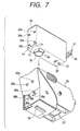
- Fig. 7 is a view of the head cartridge for black use, which is observed from the diagonally lower left back side.
- the head cartridge for black use of the present embodiment which is shown in Fig. 6 and Fig. 7, is structured with a large capacity ink tank 30 for use of black ink, and the tank holder 36 for black use which is provided with the ink jet head 29, and arranged to detachably hold the ink tank 30.
- the movable lever 31 On one side face of the ink tank 30, the movable lever 31 is arranged together with the nip 54 and the first pawl 32.
- the second pawls 33a and 33b are provided on the other side face of the ink tank 30, the second pawls 33a and 33b are provided. Further, above the second pawls 33a and 33b on the other side face of this ink tank 30, the third pawls 34a and 34b are provided.
- the ink supply port 35 which cylindrically protrudes from the bottom face of the tank; the position pin 37 used when the ink tank 30 is installed on the tank holder 36; and the prism 28 used for detecting the ink remainders in the tank.
- the first hole 26 and the second holes 38a and 38b are formed with which the first pawl 32 and the second pawls 33a and 33b engage, respectively, when the ink tank 30 is installed on the tank holder 36.
- the third holes 39a and 39b are formed where the third pawls 34a and 34b are allowed to fall into them once, respectively, for positioning during the installation process of the ink tank 30 on the tank holder 36.
- the positioning hole 27 is arranged to enable the positioning pin 37 of the ink tank 30 to be fitted.
- Fig. 8A is the top view of the tank holder.
- the joint 10 for use of ink supply which is coupled with the ink supply port 35 of the ink tank 30.
- the semicircular rib 11 is arranged as the guide rib provided with the bow-shaped curve which is directed to intersect the insertion of the tank, and also, the linear rib 12 is arranged to be positioned on the side opposite to the joint that engages with the convex portion of the semicircular rib.
- the leading end of the ink supply port 35 of the ink tank 30 abuts upon the leading end of the linear rib 12 of the tank holder 36 as show in Fig. 8B which is the section taken along line A-A in Fig. 8A even if the ink tank 30 is inserted into the tank holder 36 with an extreme inclination. Then, the ink tank moves in the direction indicated by an arrow so that the ink supply port 36 moves toward the semicircular rib 11. In this manner, only the end portion of the ink supply port of the ink tank abuts on the linear rib 12 and the semicircular rib 11.
- the movable lever and the engaging pawl are formed integrally with the tank main body by means of molding.
- the mold formation material polypropylene is adopted, because it has excellent ink resistance, gas-barrier capability, and transparency, and also, it is inexpensive.
- the user directs the face of the ink tank 30 on the ink supply port 35 side toward the upper surface of the tank holder 36.
- he places the second pawls 33a and 33b of the ink tank 30 to be inclined downward, and begins to insert the ink tank 30 into the interior of the tank holder 36.
- the ink tank 30 is inserted along the inclined surface of the tank holder 36 on the right side face in Figs. 9C and 9D to enable the third pawls 34a and 34b of the ink tank 30 to engage with the third holes 39a and 39b of the tank holder 36, and the second pawls 33a and 33b of the ink tank 30 with the second holes 38a and 38b of the tank holder 36.
- the engagement between the third holes 39a and 39b and the third pawls 34a and 34b is made to perform the function of the guide required to operate the rotation of the ink tank 30 exactly later with the positions of the second holes 38a and 38b as the fulcrum thereof.
- ink retained in the ink absorbent 55 is introduced to the ink jet head 29 through the joint member 56 of the ink supply port 35, and discharged from the discharge ports (not shown) by the application of energy generated by the electrothermal transducing devices (not shown) in the head 29,
- the movable lever 31 when the ink tank 30 is removed, the movable lever 31 is bent inward to withdraw the first pawl 32 from the first hole 26 of the tank holder 36. Then, the nip 54 of the movable lever 31 is pulled up to remove the ink tank 30 from the tank holder 36 easily.
- the positioning pin 37 is positioned in the vicinity of the prism 28.
- the positioning pin is arranged, in particular, in order to locate the prism 28 between the positioning pin 37 and the second pawls 33a and 33b, which become the engagement fulcrum at the time of the ink tank installation. In this way, it becomes possible to enhance the portioning precision of the direction of the horizontal rotation of the prism 28 (in the vertical direction on the surface of Fig. 6 and Fig. 7 to be described later) centering on the second holes 33a and 33b.
- the plane of the positioning pin 37 on the second pawls 33a and 33b side is made to be an abutting portion.
- the plane portion is provided for the side face of the positioning hole 27 of the holder 36 so that the abutting portion of the positioning pin 37 is received by the surface or line, but not just a point.
- Figs. 10A is a cross-sectional view which shows the case where the large capacity ink tank 30 for black use shown in Fig. 6 is held in the horizontal posture, and installed on the tank holder 36 by lowering it straightly in such posture.
- Fig. 10B is a cross-sectional view which shows the state where the ink tank kept in the posture shown in Fig. 10A is installed on the tank holder.
- the distance is defined as W between the side wall of the tank holder 36 where the first hole 38 is arranged to engage with the first pawl 32 of the movable lever 31 provided for the one side face of the ink tank 30, and the side wall of the tank holder 36 on which the second hole 38a (38b) is arranged to engage with the second pawl 33a (33b) on the side face opposite to the side face where the movable lever of the ink tank 30 is provided.
- the distance is defined as S between the outer side face of the base 31a which becomes the bending point of the warping of the movable lever 31 arranged on one side face of the ink tank 30, and the leading end of the second pawl 33a (33b) on the side face opposite to the side where the movable lever 31 of the ink tank 30 is provided.
- the distance S for the ink tank 30 is set greater than the distance W for the tank holder 36.
- ink tanks are manufactured by way of trail with various changes of the difference between the distance S for the ink tank 30 and the distance W for the tank holder 36. Then, with the experiments by the actual installation thereof, it has been determined that the difference of 0.4 to 1.0 mm demonstrates the best condition. In other words, if the difference is small than 0.4 mm, the ink tank 30 is held to reside in the position in the half-finished manner as shown in Figs. 4A and 4B (the position which the user tends to erroneously recognize as if the ink tank were installed appropriately). If, on the contrary, the difference is more than 1.0 mm, it becomes difficult to insert the second pawl 33a (33b) into the second hole 38a (38b) of the tank holder 36.
- the sectional configuration (the length of the extrusion) of the second pawl 33a (33b) is formed to be shorter on the lower side, and the lower side and the upper side are continuous on the inclined surface as shown in Fig. 9B or Fig. 10A.
- the upper side of the second pawl 33a (33b) advances from diagonally above to the second hold 38a (38b) of the tank holder.
- the upper side and the lower side are in the same length or the structure is arranged to make the upper side longer than the lower side, the upper side of the second pawl 33a (33b) may be in contact with the upper surface of the second hold 38a (38b) earlier, and such contact may impede the insertion thereof any further.
- the upper side of the second pawl 33a (33b) is made shorter than the lower side. Then, the insertion is made easier from diagonally above without letting the upper side of the second pawl 33a (33b) abut upon the second hole 38a (38b) when ink tank is installed. In this way, it becomes possible to make the rotational insertion with a part of the upper side of the second pawl 33a (33b) as the fulcrum assuredly.
- the lower side of the second pawl 33a (33b) is longer, while the upper side thereof is made shorter, and then, the structure is arranged so that the lower side and the upper side is made continuous by means of the inclined surface.
- the ink tank is prevented from being installed on the tank holder in the wrong direction, and the normal installation is easily carried out without fail.
- the second pawl 33a (33b) is blocked in a position considerably above the second hole 38a (38b) of the tank holder 36 even if it is intended to install the ink tank 30, which is held in the horizontal posture as shown in Fig. 10A, on the tank holder 36 by lowering it straightly as it is as shown in Fig. 10B.
- the first pawl 32 of the movable lever 31 is also blocked on the outer side of the tank holder 36 considerably above the first hold 38. Then, it becomes difficult to press the ink tank any further. Even if it is pressed down forcefully, the first pawl 32 is not allowed to engage with the first hole 38. Therefore, the use can recognize that the ink tank is not installed on the tank holder exactly. In this way, the user is prompted to operate again in order to install the ink tank correctly.
- the height y of the second pawl 33a (33b) is higher than the height x of the third pawl 34a (34b). This is because if the height x of the third pawl 34a (34b) is made equal to or higher than the height y of the second pawl 33a (33b), it becomes difficult for the third pawl to perform its function of guide as shown in Figs. 9C and 9D or the pawl is stuck out to the outer side of the tank holder 36, and may undesirably interfere with the guide shaft of a printer in some cases (see the reference numeral 105 in Fig. 20).
- the height y of the second pawl is 2.3 mm to 2.5 mm, while the height x of the third pawl is 1.7 to 2.0 mm.
- the second pawl is higher than the height x of the third pawl by 0.3 to 0.8 mm.
- the cartridge for black use shown in Fig. 6 and Fig. 7 is provided with the prism for use of the remainders detection in the ink tank, and the positioning pin 37 for positioning the ink tank when it is installed on the tank holder.
- the ink tank having the second pawl of the present invention is applied to the ink tank structured as described above, it becomes possible to prevent any forceful operation of ink tank installation. Then, the damage that may be caused to the positioning pin following the forceful installation is minimized. Therefore, even when the attaching and detaching operations are repeatedly performed, the damage to the positioning pin is controlled to maintain the highly precise tank installation.
- This is more preferable for the mode in which the presence or the absence of liquid in the ink tank is detected by the remainders detection mechanism provided with the prism and the light emitting means and photodetection means which are externally arranged (a recording apparatus main body or the like) as shown in Fig. 6 and Fig. 7, because such mode requires more rigid precision of the installed position of the ink tank on the tank holder.
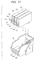
- Fig. 11 is perspective views which illustrate the front side of the ink tank and the tank holder that constitute the ink jet head cartridge for color use in accordance with a second embodiment of the present invention, observed from diagonally right upper front side.
- Fig. 12 is perspective views which illustrate such ink tank and tank holder, observed from diagonally left lower back side.
- the head cartridge for color use shown in Fig. 11 and Fig. 12 is provided with a cyan ink tank 40c, a magenta ink tank 40m, an yellow ink tank 40y, and the ink jet head, and it is structured with a tank holder 46 which can detachably hold each of the ink tanks 40c, 40m, and 40y.
- a tank holder 46 which can detachably hold each of the ink tanks 40c, 40m, and 40y.
- each of the movable levers 41c, 41m, and 41y is arranged on one side of each of the color ink tanks 40c, 40m, and 40y.
- Each of the movable levers is provided with each of the nips 54c, 54m, and 54y, and each of the first pawls 42c, 42m, and 42y, respectively.
- each of the second pawls 43c, 43m, and 43y is arranged on the other side face of each of the color ink tanks 40c, 40m, and 40y. Further, on the other side of each of the color ink tanks 40c, 40m, and 40y, the third pawls 44c, 44m, and 44y are arranged above the second pawls 43c, 43m, and 43y, respectively.
- the ink supply port 45c (45m and 45y) which cylindrically protrudes from the bottom face of the tank; the position pin 47c (47m and 47y) used when the ink tank 40c (40m and 40y) is installed on the tank holder 46; and the prism 51c (51m and 51y) used for detecting the ink remainders in the tank.
- the first hole 48c (48m and 48y) and the second hole 49c (49m and 49y) are formed with which the first pawl 42c (42m and 42y) and the second pawl 43c (43m and 43y) engage, respectively, when the ink tank 40c (40m and 40y) is installed on the tank holder 46.
- the third holes 50c (50m and 50y) is formed where the third pawl 44c (44m and 44y) is allowed to fall into it once, respectively, for positioning during the installation process of each ink tank on the tank holder 46.
- the positioning hole 53c (53m and 53y) is arranged to enable the positioning pin 47c (47m and 47y) of the ink tank 40c (40m and 40y) to be fitted.
- each of the ink tanks is detachably installed on the tank holder. Then, each of the ink tanks is made exchangeable, thus reducing the running costs of printing operation of an ink jet recording apparatus.
- the semicircular rib 14 (14y, 14m, and 14c) and the linear rib 15 (15y, 15m, and 15c) on the side of the joint 13 (13y, 13m, and 13c) of the tank holder 46 as clear from the representation of the tank holder 46 on the top view shown in Fig. 13. Therefore, the use can easily install the ink tanks on the tank holder.
- the distance S (see Fig. 10) between the outer side face of the base portion of the movable lever of the ink tank and the leading end of the second engaging pawl is set is set greater than the distance W (see Fig. 10) between the inner side faces of the side wall having the first engagement hale and the side wall having the second engagement hole of the tank holder. Then, unless the correct operation is carried out, the ink tank is not fixed to the tank holder because the tank does not engage with the holder. With a simple and an inexpensive method, it becomes possible to let the user install the ink tank on the tank holder correctly and safely without difficulty.
- two engaging pawls (the second pawls) 33a and 33b are provided for one side face (back face) of the large capacity ink tank 30 for black ink use of the first embodiment.
- the tired pawls 34a and 34b are arranged, respectively.
- the first pawl 32 is arranged for the movable lever 31.
- the second holes 38a and 38b, and the third holes 39a and 39b are arranged for the tank holder 36, there are arranged the second holes 38a and 38b, and the third holes 39a and 39b to receive the second pawls 33a and 33b, and the third pawls 34a and 34b, respectively.
- each length of the second pawls 33a and 33b of the ink tank 30 in the transverse direction is defined as La
- the gap between the second pawls 33a and 33b is defined as Lc
- each length of the second holes 38a and 38b of the tank holder 36 in the transverse direction is defined as Ma
- the gap between the second holes 38a and 38b is defined as Mc.
- the length Ma of the second hole is made longer than the length La by 0.02 to 0.12 mm so as to enable the second pawls 33a and 33b to be inserted into the second holes 38a and 38b.
- the engaging pawls (the second pawls) 43y, 43m, and 43c are provided for one side face (back face) of each of the ink tanks 40y, 40m, and 40c for color use of the second embodiment. Further, above each of the second pawls 43y, 43m, and 43c in the vertical direction on the same side face, the tired pawls 44y, 44m, and 44c are arranged, respectively. Further, on the side face (front face) opposite to the side face where the second pawls 43y, 43m, and 43c are provided, the first pawls 42y, 42m, and 42c are arranged for the movable levers 41y, 41m, and 41c, respectively.
- the second holes 49y, 49m, and 49c there are arranged the second holes 49y, 49m, and 49c, and the third holes 50y, 50m, and 50c to receive the second pawls 49m,49m, and 49c, and the third pawls 50y, 50m, and 50c, respectively.
- each length of the second pawls 43y, 43m, and 43c of each of the color ink tanks 40y, 40m, and 40c is the same, respectively, in the transverse direction (the width direction of the ink tank), and defined as Le
- each length of the second holes 49y, 49m, and 49c of the tank holder 46 is the same, respectively, in the transverse direction (the width direction of the tank holder) and defined as Me.
- the length Me of the second hole is made longer than the length Le by 0.02 to 0.12 mm so as to enable the second pawls 43y, 43m, and 43c to be inserted into the second holes 49y, 49m, and 49c.
- Figs. 14A and 14B are cross-sectional views which illustrate the principal part of the ink jet head cartridge in accordance with a third embodiment of the present invention.
- the present embodiment is the variational example of the first embodiment.
- the same reference marks are applied. Then, the description thereof will be omitted.
- Fig. 14A shows the state where each height of the semicircular rib 11a and the linear rib 12a is arranged to become lower gradually as each of them approach the joint 10 more closely.
- Fig. 14B shows the state where each height of the semicircular rib 11b and the linear rib 12b is arranged to become higher gradually on the contrary.
- Fig. 15 is a view which shows the head cartridge for color use in accordance with a fourth embodiment of the present invention, observed from diagonally lower left back face.
- the engaging pawls (the second pawls) 43y, 43m, and 43c are arranged as shown in Fig. 6. Further, above the second pawls 43y, 43m, and 43c in the vertical direction on the same side face, the third pawls 44y, 44m, and 44c are arranged. Further, on the side face (front face) opposite to the side where the second pawls 43y, 43m, and 43c are arranged, the first pawls 42y, 42m, and 42c are arranged for the movable levers 41y, 41m, and 41c.
- the second holes 49y, 49m, and 49c, and also, the third holes 50y, 50m, and 50c are arranged to receive the second pawls 43y, 43m, and 43c and the third pawls 44y, 44m, and 44c, respectively.
- each position of the second pawls is changed so that the second pawl for the cyan ink tank 40c is positioned at the right end toward the back face; the one for the magenta ink tank 40m, in the center; and the one for the yellow ink tank 40y, on the left end, respectively.
- the positional changes are made likewise per color ink tank.
- each position of the second holes 49y, 49m, and 49c and the third holes 50y, 50m, and 50c of the tank holder 46 that correspond to the second pawls 43y, 43m, and 43c and the third pawls 44y, 44m, and 44c, respectively, is changed to be on the right end, in the center, and the left end accordingly.
- the second pawl 43y and the third pawl 44y of the yellow ink tank 40y engage only with the corresponding second hole 49y and third hole 50y of the tank holder 46, but do not engage with any other second holes 49m and 49c or the third holes 50m and 50c.
- the same is applicable to the pawls of the magenta ink tank 40m or the cyan ink tank 40c. These are not allowed to engage with the holes unless corresponding to each other.
- the engaging pawl on the back face of each color ink tank is arranged to engage with the hole of the tank holder only in the position determined correctly for each of color ink tanks for the tank holder accordingly. Therefore, it is made possible for the user to recognize whether or not the respective ink tanks are correctly installed on the tank holder.
- Fig. 16 is a view which shows the head cartridge for color use in accordance with a fifth embodiment of the present invention, observed from diagonally lower left back face.
- each length of the second pawls 43y, 43m, and 43c of the color ink tanks 40y, 40m, and 40c is the same in the transverse direction (the width direction of the ink tank), each position of the second pawls is changed so that the one for the cyan ink tank 40c is deviated to the lower end side on the back face; the one for the magenta ink tank 40m, slightly above the cyan tank 40c; and the one for the yellow ink tank 40y, slightly above the magenta tank 40m.
- the third pawls 44y, 44m, and 44c are arranged, and for these third pawls, too, the same changes are made per color tank. Also, each position of the second holes 49y, 49m, and 49c and the third holes 50y, 50m, and 50c of the tank holder 46 is changed corresponding to the second pawls 43y, 43m, and 43c and the third pawls 44y, 44m, and 44c accordingly.
- the second pawl 43y and the third pawl 44y of the yellow ink tank 40y engage only with the corresponding second hole 49y and third hole 50y of the tank holder 46, but do not engage with any other second holes 49m and 49c or the third holes 50m and 50c.
- the same is applicable to the pawls of the magenta ink tank 40m or the cyan ink tank 40c. These are not allowed to engage with the holes unless corresponding to each other.
- the engaging pawl on the back face of each color ink tank is arranged to engage with the hole of the tank holder only in the position determined correctly for each of color ink tanks for the tank holder accordingly. Therefore, it is made possible for the user to recognize whether or not the respective ink tanks are correctly installed on the tank holder.
- Fig. 17 shows the head cartridge for color use in accordance with a sixth embodiment of the present invention, observed from diagonally lower left back face.
- each pawl configuration of the second pawls 43y, 43m, and 43c of the color ink tanks 40y, 40m, and 40c is changed so that for the one for the cyan ink tank 40c has a convex extrusion in the lower right end of the rectangular parallelepiped; the one for the magenta ink tank 40m, in the lower central portion thereof; and the one for the yellow ink tank 40y, on the lower left end, respectively.
- the third pawls 44y, 44m, and 44c are arranged, and for these third pawls, too, the same changes are made per color tank. Also, each configuration of the second holes 49y, 49m, and 49c and the third holes 50y, 50m, and 50c of the tank holder 46 is changed corresponding to the second pawls 43y, 43m, and 43c and the third pawls 44y, 44m, and 44c accordingly.
- the second pawl 43y and the third pawl 44y of the yellow ink tank 40y engage only with the corresponding second hole 49y and third hole 50y of the tank holder 46, but do not engage with any other second holes 49m and 49c or the third holes 50m and 50c.
- the same is applicable to the pawls of the magenta ink tank 40m or the cyan ink tank 40c. These are not allowed to engage with the holes unless corresponding to each other.
- the engaging pawl on the back face of each color ink tank is arranged to engage with the hole of the tank holder only in the position determined correctly for each of color ink tanks for the tank holder accordingly. Therefore, it is made possible for the user to recognize whether or not the respective ink tanks are correctly installed on the tank holder.
- Fig. 18 is a perspective view which shows the monochromatic tank holder for the head cartridge, and the larger and smaller ink tanks in accordance with a seventh embodiment of the present invention.
- Fig. 19A is a plan view which shows the state where the larger capacity ink tank is installed on the monochromatic tank holder.
- Fig. 19B is a plan view which shows the state where a smaller capacity ink tank is installed on the monochromatic tank holder.
- the ink tank 30 and the ink tank 40 are the same as those of the first and second embodiments.
- the dimensional values of the second pawls are also the same, respectively.
- the second holes 88a (right) and 88b (left) to engage with the second pawls 33a and 33b of the ink tank 30, respectively.
- the second hold 88c (center) is also arranged to engage with the second pawl 43 of the ink tank 40.
- the dimensional value of the second hole 88a (right) is the same as that of the second hole 38a (see Fig. 7) in accordance with the first embodiment.
- the dimensional value of the second hole 88b (left) is the same as that of the second hole 38b (see Fig. 7) in accordance with the first embodiment.
- the dimensional value of the second hole 88c (center) is the same as those of the second holes 49y, 49m, and 49c (see Fig. 12) in accordance with the second embodiment.
- Fig. 20 is a perspective view which schematically shows the ink jet recording apparatus capable of mounting on it the ink jet head cartridge and the ink tank of the present invention.
- the lead screw 104 and the guide shaft 105 which are arranged to be in parallel to each other, are provided in a housing.
- the carriage 101 is movably installed in the direction parallel to the lead screw 104 and the guide shaft 105. The carriage 101 moves in parallel with the lead screw 104 when the lead screw rotates by means of a carriage motor (not shown).
- the ink jet head cartridge provided with the ink jet head 110 is mounted.
- the sheet pressure plate 109 is arranged.
- the ink jet recording apparatus is provided with the sheet feed roller 107 that carries the recording sheet 106 which serves as a recording medium toward the recording area of the ink jet head 110, and the sheet exhaust roller 108 for exhausting the recording sheet 106 after recording by use of the ink jet head 110.
- the sheet feed roller 107 and the sheet exhaust roller 108 are rotated by means of a motor (not shown).
- the cartridges can mount three color ink tanks each as in the second embodiment
- the two head cartridges may be one photographic head cartridge having magenta and cyan tanks for use of lighter density colors, as well as the black ink tank, and one color head cartridge that can discharge yellow, magenta, and cyan ink.
- the recording apparatus can print in six ink colors, and also, it can print in the photographic mode or the aforesaid photographic head cartridge may be replaced with the ink tank only for black use as in the first embodiment so that a text printing can be made at higher speeds, and that images are printed in business colors at higher speeds as required.
- An ink tank is to be held detachably on a tank holder provided with a movable lever having a first engaging pawl to engage with a first engagement hole provided for one side wall of the tank holder, and a second engaging pawl to engage with a second engagement hole provided for side wall opposite to the one side wall having the first engagement hole of the tank holder.
- the distance S between the outer side face of the base portion of the movable lever of the ink tank and the leading end of the second engaging pawl is set to be larger than the distance between the inner wall faces of the side wall having the first engagement hole of the tank holder and the side wall having the second engagement hole.
Landscapes
- Ink Jet (AREA)
Applications Claiming Priority (6)
| Application Number | Priority Date | Filing Date | Title |
|---|---|---|---|
| JP30613998A JP2000127428A (ja) | 1998-10-27 | 1998-10-27 | インクタンク、タンクホルダー、インクジェットヘッドカートリッジ、インク供給システムおよびインクジェット記録装置 |
| JP30614498 | 1998-10-27 | ||
| JP30553298A JP3697088B2 (ja) | 1998-10-27 | 1998-10-27 | タンクホルダ |
| JP30553298 | 1998-10-27 | ||
| JP10306144A JP2000127430A (ja) | 1998-10-27 | 1998-10-27 | インクタンク、インクジェットヘッドカートリッジ、およびインクジェット記録装置 |
| JP30613998 | 1998-10-27 |
Publications (3)
| Publication Number | Publication Date |
|---|---|
| EP1000749A2 true EP1000749A2 (fr) | 2000-05-17 |
| EP1000749A3 EP1000749A3 (fr) | 2000-07-26 |
| EP1000749B1 EP1000749B1 (fr) | 2008-09-24 |
Family
ID=27338764
Family Applications (1)
| Application Number | Title | Priority Date | Filing Date |
|---|---|---|---|
| EP99121296A Expired - Lifetime EP1000749B1 (fr) | 1998-10-27 | 1999-10-26 | Cartouche pour tête à jet d'encre et dispositif d'enregistrement par jet d'encre |
Country Status (7)
| Country | Link |
|---|---|
| US (1) | US6390601B1 (fr) |
| EP (1) | EP1000749B1 (fr) |
| KR (1) | KR100357680B1 (fr) |
| CN (4) | CN1241746C (fr) |
| AU (1) | AU756458B2 (fr) |
| CA (1) | CA2287605C (fr) |
| DE (1) | DE69939618D1 (fr) |
Cited By (8)
| Publication number | Priority date | Publication date | Assignee | Title |
|---|---|---|---|---|
| EP1247650A3 (fr) * | 2001-04-03 | 2003-08-13 | Seiko Epson Corporation | Cartouche d'encre et appareil d'enregistrement à jet d'encre |
| FR2841177A1 (fr) * | 2002-06-17 | 2003-12-26 | Seiko Epson Corp | Appareil d'enregistrement a jet d'encre et cartouche d'encre |
| US7293864B2 (en) | 2003-08-08 | 2007-11-13 | Seiko Epson Corpoation | Liquid container with mounting and removal operation guide groove regulating movement |
| KR100836965B1 (ko) * | 2001-04-03 | 2008-06-10 | 세이코 엡슨 가부시키가이샤 | 잉크 카트리지 |
| WO2008088500A1 (fr) * | 2006-12-21 | 2008-07-24 | Eastman Kodak Company | Réservoir à fluide de dispositif d'impression, présentant des éléments d'alignement |
| US7438401B2 (en) | 2002-06-17 | 2008-10-21 | Seiko Epson Corporation | Inkjet recording apparatus and ink cartridge |
| US7954931B2 (en) | 2006-11-06 | 2011-06-07 | Seiko Epson Corporation | Container holder, liquid consuming apparatus, and liquid container |
| US8091995B2 (en) | 2006-11-06 | 2012-01-10 | Seiko Epson Corporation | Liquid container, container holder and liquid consuming apparatus |
Families Citing this family (36)
| Publication number | Priority date | Publication date | Assignee | Title |
|---|---|---|---|---|
| JP3450798B2 (ja) | 1999-04-27 | 2003-09-29 | キヤノン株式会社 | 液体供給システム、該システムに用いられる液体収納容器、該システムを用いたインクジェットヘッドカートリッジ |
| JP3492283B2 (ja) * | 2000-03-31 | 2004-02-03 | キヤノン株式会社 | 液体容器および記録装置 |
| CN101125491B (zh) * | 2001-04-03 | 2010-04-21 | 精工爱普生株式会社 | 墨盒 |
| US6749292B2 (en) * | 2001-10-18 | 2004-06-15 | Hewlett-Packard Development Company, L.P. | Replaceable ink container for an inkjet printing system |
| JP4027111B2 (ja) * | 2002-02-15 | 2007-12-26 | キヤノン株式会社 | 液体噴射記録ヘッド |
| CN2555154Y (zh) * | 2002-08-20 | 2003-06-11 | 珠海天威飞马打印耗材有限公司 | 连续供墨器 |
| US7134747B2 (en) * | 2002-09-30 | 2006-11-14 | Canon Kabushiki Kaisha | Ink container, recording head and recording device using same |
| TWI259149B (en) * | 2002-09-30 | 2006-08-01 | Canon Kk | Ink container and recording apparatus |
| US7261397B2 (en) * | 2003-08-19 | 2007-08-28 | Canon Kabushiki Kaisha | Tank unit, ink jet recording head and method of manufacturing tank unit and ink jet recording head |
| JP4038683B2 (ja) * | 2003-10-10 | 2008-01-30 | 理想科学工業株式会社 | インク容器 |
| JP4649274B2 (ja) * | 2005-06-21 | 2011-03-09 | キヤノン株式会社 | 位置検出方法 |
| JP4585927B2 (ja) | 2005-06-24 | 2010-11-24 | キヤノン株式会社 | インクジェット記録装置 |
| JP4882733B2 (ja) * | 2006-03-30 | 2012-02-22 | ブラザー工業株式会社 | インクカートリッジ |
| US7690774B2 (en) | 2006-12-21 | 2010-04-06 | Eastman Kodak Company | Printing device fluid reservoir with gripping features |
| WO2009151436A1 (fr) * | 2008-06-08 | 2009-12-17 | Hewlett-Packard Development Company, L.P. | Cartouche de fluide à accessoire caractéristique pour nettoyer les surfaces montantes de support |
| JP2012051315A (ja) * | 2010-09-03 | 2012-03-15 | Seiko Epson Corp | ホルダー、ホルダーに着脱可能な液体収容容器、及び、液体噴射装置 |
| CN105377561B (zh) | 2013-07-10 | 2017-12-12 | 惠普发展公司,有限责任合伙企业 | 包括闩手柄和肋的流体容器部 |
| JP5960345B2 (ja) | 2013-09-18 | 2016-08-02 | キヤノン株式会社 | インクカートリッジおよびインクジェットプリンタ |
| CN105722684B (zh) | 2013-09-18 | 2017-12-05 | 佳能株式会社 | 墨盒和喷墨打印机 |
| JP6512774B2 (ja) | 2014-08-25 | 2019-05-15 | キヤノン株式会社 | 液体収納容器の保持部材、プリントヘッドおよびプリンタ |
| US9987849B2 (en) | 2015-08-21 | 2018-06-05 | Canon Kabushiki Kaisha | Liquid ejecting device |
| USD813338S1 (en) * | 2015-09-17 | 2018-03-20 | Vista Outdoor Operations Llc | Riflescope turret |
| JP6611564B2 (ja) | 2015-10-30 | 2019-11-27 | キヤノン株式会社 | 液体収納ボトルおよび液体収納ボトルのパッケージ |
| JP6825286B2 (ja) * | 2016-09-23 | 2021-02-03 | セイコーエプソン株式会社 | 液体噴射装置 |
| CN106926586B (zh) * | 2017-03-29 | 2019-02-22 | 珠海纳思达企业管理有限公司 | 墨盒及墨盒的安装方法 |
| JP2019093669A (ja) | 2017-11-27 | 2019-06-20 | キヤノン株式会社 | 液体補充容器及び液体補充システム |
| JP7110038B2 (ja) | 2018-09-06 | 2022-08-01 | キヤノン株式会社 | 液体貯留容器および液体吐出装置 |
| JP7275706B2 (ja) * | 2019-03-20 | 2023-05-18 | セイコーエプソン株式会社 | 液体吐出ユニットおよび液体吐出装置 |
| JP7352815B2 (ja) * | 2019-04-26 | 2023-09-29 | セイコーエプソン株式会社 | 液体吐出ユニットおよび液体吐出装置 |
| JP7532055B2 (ja) | 2020-03-24 | 2024-08-13 | キヤノン株式会社 | 液体供給装置 |
| JP7504641B2 (ja) | 2020-03-27 | 2024-06-24 | キヤノン株式会社 | 液体吐出装置 |
| JP7520574B2 (ja) | 2020-05-22 | 2024-07-23 | キヤノン株式会社 | 液体カートリッジおよび液体吐出装置 |
| US11801370B2 (en) * | 2021-02-17 | 2023-10-31 | Funai Electric Co., Ltd. | Gas management for jetting cartridge |
| JP7775026B2 (ja) | 2021-10-28 | 2025-11-25 | キヤノン株式会社 | 液体吐出装置 |
| JP7799435B2 (ja) | 2021-10-28 | 2026-01-15 | キヤノン株式会社 | 液体吐出装置 |
| CN114506158B (zh) * | 2022-02-28 | 2022-10-28 | 深圳市思孚纸品包装有限公司 | 一种方便快速烘干的印刷机墨盒 |
Family Cites Families (6)
| Publication number | Priority date | Publication date | Assignee | Title |
|---|---|---|---|---|
| US5825388A (en) | 1994-12-27 | 1998-10-20 | Brother Kogyo Kabushiki Kaisha | Ink jetting apparatus |
| JPH0924619A (ja) * | 1995-07-12 | 1997-01-28 | Brother Ind Ltd | インクカートリッジ |
| DE69624063T2 (de) | 1995-11-08 | 2003-02-13 | Canon K.K., Tokio/Tokyo | Farbstoffnachfüllverfahren und -vorrichtung, Tintenbehälter und Tintenstrahlaufzeichnungsgerät mit einer solchen Vorrichtung |
| US6464338B1 (en) | 1996-07-31 | 2002-10-15 | Canon Kabushiki Kaisha | Ink jet head with separable tank holding member and recording unit |
| JP3295339B2 (ja) | 1996-08-30 | 2002-06-24 | キヤノン株式会社 | インクタンク、ホルダー、インクジェットカートリッジおよびキャップ |
| JP3287791B2 (ja) * | 1997-07-30 | 2002-06-04 | キヤノン株式会社 | 液体収容室を有する液体収容容器への液体充填方法及び液体充填装置 |
-
1999
- 1999-10-20 US US09/421,258 patent/US6390601B1/en not_active Expired - Lifetime
- 1999-10-26 DE DE69939618T patent/DE69939618D1/de not_active Expired - Lifetime
- 1999-10-26 CA CA002287605A patent/CA2287605C/fr not_active Expired - Fee Related
- 1999-10-26 EP EP99121296A patent/EP1000749B1/fr not_active Expired - Lifetime
- 1999-10-26 AU AU56099/99A patent/AU756458B2/en not_active Ceased
- 1999-10-26 KR KR1019990046516A patent/KR100357680B1/ko not_active Expired - Fee Related
- 1999-10-27 CN CNB021458022A patent/CN1241746C/zh not_active Expired - Fee Related
- 1999-10-27 CN CN99123175A patent/CN1113754C/zh not_active Expired - Fee Related
-
2002
- 2002-10-14 CN CN02145803A patent/CN1410276A/zh active Pending
- 2002-10-14 CN CNB021458049A patent/CN1210158C/zh not_active Expired - Fee Related
Cited By (24)
| Publication number | Priority date | Publication date | Assignee | Title |
|---|---|---|---|---|
| EP1541360A3 (fr) * | 2001-04-03 | 2008-09-24 | Seiko Epson Corporation | cartouche d'encre |
| US7934822B2 (en) | 2001-04-03 | 2011-05-03 | Seiko Epson Corporation | Ink cartridge |
| EP1500512A1 (fr) * | 2001-04-03 | 2005-01-26 | Seiko Epson Corporation | Cartouche d'encre et appareil d'enregistrement à jet d'encre |
| US6863376B2 (en) | 2001-04-03 | 2005-03-08 | Seiko Epson Corporation | Ink cartridge and ink-jet recording apparatus |
| US7018030B2 (en) | 2001-04-03 | 2006-03-28 | Seiko Epson Corporation | Ink cartridge and ink-jet recording apparatus |
| SG158732A1 (en) * | 2001-04-03 | 2010-02-26 | Seiko Epson Corp | Ink cartridge and ink-jet recording apparatus |
| EP1247650A3 (fr) * | 2001-04-03 | 2003-08-13 | Seiko Epson Corporation | Cartouche d'encre et appareil d'enregistrement à jet d'encre |
| US7178902B2 (en) | 2001-04-03 | 2007-02-20 | Seiko Epson Corporation | Ink cartridge and ink-jet recording apparatus |
| US7614732B2 (en) | 2001-04-03 | 2009-11-10 | Seiko Epson Corporation | Ink cartridge |
| KR100836965B1 (ko) * | 2001-04-03 | 2008-06-10 | 세이코 엡슨 가부시키가이샤 | 잉크 카트리지 |
| US7566112B2 (en) | 2001-04-03 | 2009-07-28 | Seiko Epson Corporation | Ink cartridge and ink-jet recording apparatus |
| EP1685966A1 (fr) * | 2002-06-17 | 2006-08-02 | Seiko Epson Corporation | Dispositif d'impression à jet d'encre et cartouche d'encre |
| US7438401B2 (en) | 2002-06-17 | 2008-10-21 | Seiko Epson Corporation | Inkjet recording apparatus and ink cartridge |
| US7452063B2 (en) | 2002-06-17 | 2008-11-18 | Seiko Epson Corporation | Inkjet recording apparatus and ink cartridge |
| AU2003204751B2 (en) * | 2002-06-17 | 2008-07-17 | Seiko Epson Corporation | Inkjet Recording Apparatus and Ink Cartridge |
| US7018027B2 (en) | 2002-06-17 | 2006-03-28 | Seiko Epson Corporation | Inkjet recording apparatus and ink cartridge |
| FR2841177A1 (fr) * | 2002-06-17 | 2003-12-26 | Seiko Epson Corp | Appareil d'enregistrement a jet d'encre et cartouche d'encre |
| US7293864B2 (en) | 2003-08-08 | 2007-11-13 | Seiko Epson Corpoation | Liquid container with mounting and removal operation guide groove regulating movement |
| US7954935B2 (en) | 2003-08-08 | 2011-06-07 | Seiko Epson Corporation | Liquid container with mounting and removal guide for regulating movement of the liquid container |
| US7954931B2 (en) | 2006-11-06 | 2011-06-07 | Seiko Epson Corporation | Container holder, liquid consuming apparatus, and liquid container |
| US8091995B2 (en) | 2006-11-06 | 2012-01-10 | Seiko Epson Corporation | Liquid container, container holder and liquid consuming apparatus |
| WO2008088500A1 (fr) * | 2006-12-21 | 2008-07-24 | Eastman Kodak Company | Réservoir à fluide de dispositif d'impression, présentant des éléments d'alignement |
| US7810917B2 (en) | 2006-12-21 | 2010-10-12 | Eastman Kodak Company | Printing device fluid reservoir with alignment features |
| US8052263B2 (en) | 2006-12-21 | 2011-11-08 | Eastman Kodak Company | Printing device fluid reservoir with alignment features |
Also Published As
| Publication number | Publication date |
|---|---|
| CN1410276A (zh) | 2003-04-16 |
| CN1410277A (zh) | 2003-04-16 |
| CN1210158C (zh) | 2005-07-13 |
| KR100357680B1 (ko) | 2002-10-19 |
| AU5609999A (en) | 2000-05-04 |
| AU756458B2 (en) | 2003-01-16 |
| DE69939618D1 (de) | 2008-11-06 |
| CN1410275A (zh) | 2003-04-16 |
| EP1000749B1 (fr) | 2008-09-24 |
| EP1000749A3 (fr) | 2000-07-26 |
| CN1113754C (zh) | 2003-07-09 |
| CA2287605A1 (fr) | 2000-04-27 |
| CA2287605C (fr) | 2005-01-25 |
| US6390601B1 (en) | 2002-05-21 |
| CN1241746C (zh) | 2006-02-15 |
| KR20000029299A (ko) | 2000-05-25 |
| CN1252354A (zh) | 2000-05-10 |
Similar Documents
| Publication | Publication Date | Title |
|---|---|---|
| CA2287605C (fr) | Reservoir d'encre, cartouche de tete d'impression a jet d'encre et dispositif d'enregistrement a jet d'encre | |
| EP2527154B3 (fr) | Detrompage par interverrouillage d'une famille d'encre pour une cartouche d'encre | |
| US5534899A (en) | Replaceable ink tank | |
| EP0983856B1 (fr) | Réservoir d'encre avec tenue améliorée, porteur pour l'installation d'un tel réservoir, cartouche à jet d'encre, appareil d'enregistrement à jet d'encre | |
| EP0968090B1 (fr) | Receptacle d'encre pourvus de dispositifs electroniques et mecaniques assurant une totale compatibilite entre des alimentations en encre de tailles differentes | |
| EP1527882B1 (fr) | Cartouche d'encre pour appareil d'enregistrement à jet d'encre | |
| US6464338B1 (en) | Ink jet head with separable tank holding member and recording unit | |
| US20050068382A1 (en) | Liquid container | |
| CN1252758A (zh) | 固定墨盒的方法和设备 | |
| EP1281527B1 (fr) | Appareil d'enregistrement par éjection de liquide | |
| AU2002301857B2 (en) | Ink Tank, Ink Jet Head Cartridge, and Ink Jet Recording Apparatus | |
| JP2000127428A (ja) | インクタンク、タンクホルダー、インクジェットヘッドカートリッジ、インク供給システムおよびインクジェット記録装置 | |
| JP2000127430A (ja) | インクタンク、インクジェットヘッドカートリッジ、およびインクジェット記録装置 | |
| JP3376299B2 (ja) | インクタンク、タンクホルダー、およびインクジェットヘッドカートリッジ | |
| JP2007069541A (ja) | 記録装置 | |
| EP4344881A1 (fr) | Cartouche, système et ensemble de cartouches |
Legal Events
| Date | Code | Title | Description |
|---|---|---|---|
| PUAI | Public reference made under article 153(3) epc to a published international application that has entered the european phase |
Free format text: ORIGINAL CODE: 0009012 |
|
| AK | Designated contracting states |
Kind code of ref document: A2 Designated state(s): DE ES FR GB IT NL |
|
| AX | Request for extension of the european patent |
Free format text: AL;LT;LV;MK;RO;SI |
|
| PUAL | Search report despatched |
Free format text: ORIGINAL CODE: 0009013 |
|
| AK | Designated contracting states |
Kind code of ref document: A3 Designated state(s): AT BE CH CY DE DK ES FI FR GB GR IE IT LI LU MC NL PT SE |
|
| AX | Request for extension of the european patent |
Free format text: AL;LT;LV;MK;RO;SI |
|
| 17P | Request for examination filed |
Effective date: 20001208 |
|
| AKX | Designation fees paid |
Free format text: DE ES FR GB IT NL |
|
| 17Q | First examination report despatched |
Effective date: 20041214 |
|
| 17Q | First examination report despatched |
Effective date: 20041214 |
|
| GRAP | Despatch of communication of intention to grant a patent |
Free format text: ORIGINAL CODE: EPIDOSNIGR1 |
|
| GRAJ | Information related to disapproval of communication of intention to grant by the applicant or resumption of examination proceedings by the epo deleted |
Free format text: ORIGINAL CODE: EPIDOSDIGR1 |
|
| RTI1 | Title (correction) |
Free format text: INK JET HEAD CARTRIDGE AND INK JET RECORDING APPARATUS |
|
| GRAP | Despatch of communication of intention to grant a patent |
Free format text: ORIGINAL CODE: EPIDOSNIGR1 |
|
| GRAS | Grant fee paid |
Free format text: ORIGINAL CODE: EPIDOSNIGR3 |
|
| GRAA | (expected) grant |
Free format text: ORIGINAL CODE: 0009210 |
|
| AK | Designated contracting states |
Kind code of ref document: B1 Designated state(s): DE ES FR GB IT NL |
|
| REG | Reference to a national code |
Ref country code: GB Ref legal event code: FG4D |
|
| REF | Corresponds to: |
Ref document number: 69939618 Country of ref document: DE Date of ref document: 20081106 Kind code of ref document: P |
|
| NLV1 | Nl: lapsed or annulled due to failure to fulfill the requirements of art. 29p and 29m of the patents act | ||
| PG25 | Lapsed in a contracting state [announced via postgrant information from national office to epo] |
Ref country code: ES Free format text: LAPSE BECAUSE OF FAILURE TO SUBMIT A TRANSLATION OF THE DESCRIPTION OR TO PAY THE FEE WITHIN THE PRESCRIBED TIME-LIMIT Effective date: 20090104 |
|
| PG25 | Lapsed in a contracting state [announced via postgrant information from national office to epo] |
Ref country code: NL Free format text: LAPSE BECAUSE OF FAILURE TO SUBMIT A TRANSLATION OF THE DESCRIPTION OR TO PAY THE FEE WITHIN THE PRESCRIBED TIME-LIMIT Effective date: 20080924 |
|
| PLBE | No opposition filed within time limit |
Free format text: ORIGINAL CODE: 0009261 |
|
| STAA | Information on the status of an ep patent application or granted ep patent |
Free format text: STATUS: NO OPPOSITION FILED WITHIN TIME LIMIT |
|
| PG25 | Lapsed in a contracting state [announced via postgrant information from national office to epo] |
Ref country code: IT Free format text: LAPSE BECAUSE OF FAILURE TO SUBMIT A TRANSLATION OF THE DESCRIPTION OR TO PAY THE FEE WITHIN THE PRESCRIBED TIME-LIMIT Effective date: 20080924 |
|
| 26N | No opposition filed |
Effective date: 20090625 |
|
| REG | Reference to a national code |
Ref country code: FR Ref legal event code: ST Effective date: 20090831 |
|
| PGFP | Annual fee paid to national office [announced via postgrant information from national office to epo] |
Ref country code: GB Payment date: 20151026 Year of fee payment: 17 Ref country code: DE Payment date: 20151031 Year of fee payment: 17 |
|
| PG25 | Lapsed in a contracting state [announced via postgrant information from national office to epo] |
Ref country code: FR Free format text: LAPSE BECAUSE OF NON-PAYMENT OF DUE FEES Effective date: 20081031 |
|
| REG | Reference to a national code |
Ref country code: DE Ref legal event code: R119 Ref document number: 69939618 Country of ref document: DE |
|
| GBPC | Gb: european patent ceased through non-payment of renewal fee |
Effective date: 20161026 |
|
| PG25 | Lapsed in a contracting state [announced via postgrant information from national office to epo] |
Ref country code: GB Free format text: LAPSE BECAUSE OF NON-PAYMENT OF DUE FEES Effective date: 20161026 Ref country code: DE Free format text: LAPSE BECAUSE OF NON-PAYMENT OF DUE FEES Effective date: 20170503 |