EP1000751A2 - Aufzeichnungsgerät - Google Patents
Aufzeichnungsgerät Download PDFInfo
- Publication number
- EP1000751A2 EP1000751A2 EP99121302A EP99121302A EP1000751A2 EP 1000751 A2 EP1000751 A2 EP 1000751A2 EP 99121302 A EP99121302 A EP 99121302A EP 99121302 A EP99121302 A EP 99121302A EP 1000751 A2 EP1000751 A2 EP 1000751A2
- Authority
- EP
- European Patent Office
- Prior art keywords
- carriage
- cartridge
- head cartridge
- holder
- locking lever
- Prior art date
- Legal status (The legal status is an assumption and is not a legal conclusion. Google has not performed a legal analysis and makes no representation as to the accuracy of the status listed.)
- Granted
Links
- 238000007599 discharging Methods 0.000 claims description 2
- 239000007788 liquid Substances 0.000 claims description 2
- 230000007246 mechanism Effects 0.000 description 7
- 230000000694 effects Effects 0.000 description 4
- 239000000463 material Substances 0.000 description 4
- 230000006866 deterioration Effects 0.000 description 3
- 230000003247 decreasing effect Effects 0.000 description 1
- 230000005484 gravity Effects 0.000 description 1
Images



Classifications
-
- B—PERFORMING OPERATIONS; TRANSPORTING
- B41—PRINTING; LINING MACHINES; TYPEWRITERS; STAMPS
- B41J—TYPEWRITERS; SELECTIVE PRINTING MECHANISMS, i.e. MECHANISMS PRINTING OTHERWISE THAN FROM A FORME; CORRECTION OF TYPOGRAPHICAL ERRORS
- B41J2/00—Typewriters or selective printing mechanisms characterised by the printing or marking process for which they are designed
- B41J2/005—Typewriters or selective printing mechanisms characterised by the printing or marking process for which they are designed characterised by bringing liquid or particles selectively into contact with a printing material
- B41J2/01—Ink jet
- B41J2/17—Ink jet characterised by ink handling
- B41J2/175—Ink supply systems ; Circuit parts therefor
- B41J2/17503—Ink cartridges
- B41J2/1752—Mounting within the printer
-
- B—PERFORMING OPERATIONS; TRANSPORTING
- B41—PRINTING; LINING MACHINES; TYPEWRITERS; STAMPS
- B41J—TYPEWRITERS; SELECTIVE PRINTING MECHANISMS, i.e. MECHANISMS PRINTING OTHERWISE THAN FROM A FORME; CORRECTION OF TYPOGRAPHICAL ERRORS
- B41J2/00—Typewriters or selective printing mechanisms characterised by the printing or marking process for which they are designed
- B41J2/005—Typewriters or selective printing mechanisms characterised by the printing or marking process for which they are designed characterised by bringing liquid or particles selectively into contact with a printing material
- B41J2/01—Ink jet
- B41J2/17—Ink jet characterised by ink handling
- B41J2/175—Ink supply systems ; Circuit parts therefor
- B41J2/17503—Ink cartridges
- B41J2/17513—Inner structure
Definitions
- the present invention relates to a recording apparatus having a detachable cartridge, and more particularly relates to attachment and detachment mechanism of a cartridge.
- a reference pad, a contact pad, and a shelf-shaped member have been provided on the side of a head cartridge, the rear thereof, and the upper section of the rear thereof, respectively, and the head cartridge is secured onto a given position of a carriage by pass-contacting the shelf-shaped member with a snap-spring, as described in Japanese Patent Publication No. 1-125238. According to these mechanisms, the head cartridge can be attached and detached and at the same time can be electrically connected.
- the head cartridge When the head cartridge is attached or detached, it is rotated or pivoted around the reference pad. Therefore, the head cartridge is easy to interfere with a platen or a spur placed in the vicinity of the cartridge.
- a concave relief portion is provided in the platen or the position of the spur is significantly relieved, to prevent this interference, waving of the recording paper is increased for example and a state of holding the recording paper is deteriorated, resulting in deterioration of images.
- a device which can attach and detach a head cartridge at the area other than the paper path, where a spur and the like are not provided.
- a spur and the like are not provided.
- an object of the present invention is to provide head cartridge attaching and detaching mechanisms which do not interfere with a platen or a carrying rotator in the vicinity of the cartridge and has an excellent operability when the head cartridge is attached or detached, and a recording apparatus provided with the mechanisms.
- Another object of the present invention is to provide a head cartridge attaching and detaching mechanisms, in which when an ink tank replaceable head cartridge is used, the head cartridge is not dislodged during the replacement of the ink tank, and a recording apparatus provided with the mechanisms.
- Still another object of the present invention is to provide a recording apparatus including a carriage, which detachably holds a cartridge, wherein the carriage has a positioning portion on both sides and an inclined surface on the upper section of the rear surface; the carriage has positioning portions which engage with the positioning portions on both sides of the cartridge, and has a locking lever which is rotatable on the upper portion of the cartridge and secures the cartridge within the carriage by pressing the inclined surface in accordance with one-directional rotation of the locking lever; a pushing member for detaching the cartridge by pushing the upper portion of the rear surface of the cartridge in accordance with the rotation of the locking lever for securing the cartridge and the opposite-directional rotation, is provided with the locking lever; and an auxiliary engagement portion for restricting the attachment and detachment paths of the cartridge by contacting the auxiliary engagement portion during only the attachment and detachment operations of the cartridge, is provided with both of the cartridge and the carriage.
- Still another object of the present invention is to provide an ink jet recording apparatus including a carriage which detachably hold a head cartridge for discharging ink liquid droplets to record, wherein the head carriage has a positioning portion on both sides and an inclined surface on the upper portion of the rear surface, and further possesses a detachable ink tank; the carriage has positioning portions which engage with the positioning portions on both sides of the head cartridge, and has a locking lever which is rotatable on the upper portion of the head cartridge and secures the head cartridge within the carriage by pressing the inclined surface in accordance with one-directional rotation of the locking lever; and an auxiliary engagement portion for preventing the head cartridge from being rotated by the operating force without limitation using the positioning portions as the fulcrum, is provided with both of the head cartridge and the carriage.
- Still another object of the present invention is to provide an ink tank-holding holder which is held within a carriage housing and is held under detachable conditions from the housing by engagement of the operating portion of the carriage, wherein the holder has an inclined surface for shifting the holder upwardly while sliding the carriage operating portion; an engagement surface which is at the edge of the inclined surface and engages by engagement with the carriage operating portion; and an operating portion which protrudes from the housing by inclination of the holder with respect to the housing with the carriage operating portion.
- Still another object of the present invention is to provide a carriage which can detach the above-mentioned holder, wherein the carriage operating portion has a pushing member for shifting the holder upwardly while being slided on the inclined surface of the holder; an engagement surface which is the end portion of the pressing member and engages with the engagement surface of the holder; and a pressing portion which imparts a pressing force to the receiving portion of the upper surface of the holder.
- Still another object of the present invention is to provide an ink jet recording apparatus including the above-mentioned carriage.
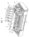
- Fig. 1 is a perspective view showing the whole configuration of an ink jet recording apparatus according to a first embodiment of the present invention.
- the ink jet recording head shown in Fig. 1 includes a carriage 1 which mounts a head cartridge as recording means and can be reciprocated along a recording material (not shown).
- the carriage 1 is guided and supported by a guide shaft 61 and a guide rail 62 in the main scanning direction.
- An endless timing belt 64 is wound through a pulley 63 provided at one end of the device housing and a pulley (not shown) provided at the other end of the device housing.
- the timing belt 64 is connected to the carriage 1 and can be driven with a motor 65 through a pulley, gear, and the like.
- the present ink jet recording apparatus has an automatic paper feeder 66.
- Recording materials (not shown) stacked on a paper feed tray 67 are supplied with the automatic paper feeder 66 one by one.
- the supplied recording materials are carried through the recording portion and discharged from a paper discharge port 68 to the outside of the device.
- ink is discharged from nozzle portions of a head cartridge and recording is carried out, while the carriage 1 is scanned along the guide shaft 61 in the recording portion.
- Fig. 2 is a perspective view showing the detailed structure of the carriage
- Fig. 3 is a perspective view showing the detailed structure of the head cartridge which is mounted on the carriage shown in Fig. 1.
- the carriage 1 shown in Fig. 2 is provided with a pocket 2 mounting a black cartridge, and a pocket 3 mounting a color cartridge.
- the grooves 4 for positioning the black cartridge are formed on both sides of the pocket 2.
- two grooves 5 for positioning the color cartridge are formed on both sides of the pocket 3.
- the pockets 2 and 3 are provided with plate springs 6 and 7 for abutting the head cartridge in a direction x, respectively.
- the upper portion of the carriage 1 is provided with rotatable locking levers 8 and 9 in correspondence to the respective pockets 2 and 3. Connectors 10 and 11 are secured so that they are slightly protruded from openings 2a and 3a of the pockets 2 and 3 on the rear surface of the carriage.
- the above-mentioned locking lever is an operating portion of the carriage, which functions as a lever with which an operator removes the head cartridge (or the head holder) from the carriage.
- a head cartridge (or a head holder) 12 which is mounted on the carriage 1, includes a nozzle portion 13 on the lower surface of the cartridge, positioning protrusions 14 on both sides thereof, and a abutting portion 15 in a direction x on one side of the cartridge. Further, many contact pads 16a-formed power switch board 17 is fixed to the rear surface of the cartridge.
- an abutting portion 18 in a direction y an inclined surface 19, which is a receiving surface which receives the pressing force the locking levers 8 and 9 impart, and a sliding portion 34 which is an inclined surface which a pushing member 33 integrally formed with the locking lever 8 slides and which causes the head carriage 12 to shift upwardly.
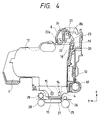
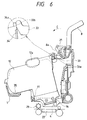
- FIGS. 4 to 6 are carriage cross-sectional views for explaining the attachment and detachment operations of the head cartridge 12.
- Fig. 4 shows a state where the head cartridge 12 was locked at a predetermined position.
- the positioning protrusion 14 of the head cartridge 12 engages with the positioning groove 4 of the carriage 1, and the abutting portion 18 in the direction y, on the upper portion of the rear surface of the head cartridge, press-contacts a receiving surface 20 of the carriage 1.
- the connector 10 contacts a contact pad 16a at a moderate contact pressure in this state thereby to perform electrical connection.
- This contact pressure performs the electrical connection and at the same time acts in such a direction that the positioning protrusion 14 is securely pressed against the positioning groove 4, while the contact pressure acts in such a direction that the abutting portion 18 is separated from the receiving surface 20.
- the position of the head cartridge 12 becomes unstable, and the position accuracy of the nozzle portion 13 is low, and the electrical connection also becomes unstable. Therefore, it is necessary to press the inclined surface 19 of the head cartridge 12 with power larger than the contact pressure of the connector 10.
- the locking lever 8 is rotatable around the fulcrum shaft 21.
- an arm 22 which swings around the fulcrum 22a, a press-contacting roller 23 attached to the swinging arm 22, and a press-contacting spring 24 which loads the arm 22.
- the position in the direction y is determined by the three points of the positioning protrusions 14 (on both sides) and abutting portion 18 in the direction y
- the position in the direction z is determined by the two points of the positioning protrusions 14 (on both sides)
- the position in the direction x is determined by the one point of the abutting portion 15 in the direction x, thereby to stabilize the position of the head cartridge.
- a pinch roller 26 press-contacting a feed roller 25, a platen 27, and a spur 29, that is a feed rotator, press-contacting a paper discharge roller 28 are placed in the vicinity of the nozzle portion 13.
- the carriage 1 reciprocates along the guide shaft 61.
- the engagement of the press-contacting roller 23 with the inclined surface 19 is first released. Accordingly, the head cartridge 12 is rotated in the direction of an arrow B using the positioning protrusions 14 on both sides as the fulcrum, by the repulsion force of the connector 10 and the head cartridge's own weight.
- the head cartridge 12 is rotated under the conditions, it interferes with the platen 27 and the spur 29.
- the auxiliary engagement portion 31 of the head cartridge 12 engages with the auxiliary guide 32 of the carriage 1 to restrict the rotation of the head cartridge 12, resulting in no interference.
- the pushing member 33 integrally formed with the locking lever 8 engages with the sliding portion 34 of the head cartridge 12, whereby the head cartridge 12 is pushed along the positioning groove 4 and auxiliary guide 32 of the carriage 1. At this time, the movement of the head cartridge 12 takes such a locus as not to interfere with the plate 27 and the spur 29 and the like.
- the locking lever is rotated to a moderate position so that the head cartridge 12 may be only pushed to a position where it is easy to remove.
- the head cartridge 12 takes such an attitude as shown in Fig. 6 at the replacement position.
- the head cartridge 12 can be held with another auxiliary engagement portion 35, the positioning protrusion 14, and the sliding portion 34 at a stable state.
- To transfer from the auxiliary engagement portion 35 to another auxiliary engagement portion 35 is to stabilize the balance of the gravity center.
- the arc portion (circle) 33a of the pushing member 33 as the concentric of the fulcrum shaft 21, the reverse rotation of the locking lever 8 in a direction of the arrow C, due to the weight of the head cartridge 12, can be prevented.
- a portion 33b of the pushing member 33 which finally engages with the sliding portion 34 when the locking lever 8 is fully rotated has a plane. Since the final engagement surface 33b of the pushing member 33 engages with an engagement surface 34a of the sliding portion 34 with a plane, the head cartridge 12 does not return to the original position and is secured in a state of inclination facing the operator side.
- a user can easily replace the head cartridge 12 in this state by grasping the knob portion (operating portion) 12a of the head cartridge 12.
- the turn of the locking lever 8 in a direction of the arrow C changes the attitude of the head cartridge 12 with the rotation of the pushing member 33. This change can occur by the head cartridge's own weight.
- the head cartridge does not contact the pinch roller 26, the platen 27, and the spur 29, not only in the proper setting state of the head cartridge, but also during the attachment and detachment operations. Therefore, the device is not broken by the replacement of a cartridge irrespective of the position of the carriage 1. Further, since it is not necessary to provide a concave relief portion in the platen 27, no deterioration of images occurs because of enlargement of waving of a recording paper.
- an ink jet recording apparatus having a simple configuration, an excellent operability, and the above-mentioned effects can be provided.
- the head cartridge 12 including a positioning protrusion 14 and an example of a carriage 1 including a positioning groove 4 were explained.
- the head cartridge may include a positioning groove
- the carriage may include a positioning protrusion.
- an ink jet recording apparatus in the present embodiment is formed such that a head cartridge is secured through the press-contacting roller 23.
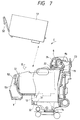
- Fig. 7 is a carriage cross-sectional view for explaining another example of a head cartridge which can be applied to a carriage of an ink jet recording apparatus of the present invention.
- the same components as in the first embodiment are denoted by the same reference numerals and the descriptions thereof are omitted.
- the configuration of the second embodiment shown in Fig. 7 is different from the first embodiment only in that an ink tank 51 is detachably formed in a head cartridge 12 which functions as a head holder.
- the user usually detaches a used ink tank from the head cartridge 12, and pushes a hook 52 of a new ink tank in a direction D in Fig. 7 to an extent that the hook 52 of the new ink tank is fitted into a groove 53 provided in the head cartridge 12.
- the head cartridge 12 which should be properly secured is detached from the original position by this pushing force, and the head cartridge must be often reset every replacement of ink.
- the head cartridge 12 is rotated using the positioning protrusion 14 as a fulcrum.
- the locking lever 8 in the state of Fig. 7 is not rotated further in a direction of arrow E by a stopper (not shown).
- an inclined surface 19 displaces a swinging arm 22 in such a direction that a press-contacting spring 24 is further compressed.
- the swinging arm 22 abuts on the stopper 8b of the locking lever 8.
- the detachment of the press-contacting roller 23 from the inclined surface 19 can be prevented.
- an auxiliary engagement portion 31 of the head cartridge 12 engages with an auxiliary guide 32 of the carriage 1. Accordingly, the rotation of the head cartridge 12 using the positioning protrusion 14 as the fulcrum can be securely stopped. That is, even if a large operating force is applied to the head cartridge 12 during the replacement of the ink tank 51, the head cartridge 12 merely floats just a little and is not detached. Then, the hook 52 of the ink tank 51 is fitted into the groove 53 of the head cartridge 12. Thus, when a user moves his hand off the cartridge, the head cartridge 12 returns to such a properly secured state as shown in Fig. 4 by a loading force of the press contacting spring 24.
- the floating of the head cartridge 12 was restricted with the stopper 8b and auxiliary engagement portion 31.
- sufficient effects can be obtained only with the auxiliary engagement portion 31 without providing the stopper 8b.
- an ink jet recording apparatus is not broken even if the replacement of a cartridge is performed anywhere irrespective of the position of a carriage, by providing an auxiliary engagement portion which contacts during attachment and detachment operations to restrict the attachment and detachment locuses, other than positioning portions which position a carriage and a cartridge, in both the carriage and head cartridge, and by providing a pushing member which pushes a head cartridge in accordance with the rotation for a removal of securing a locking lever, and that a deterioration of images, which are generated by providing a platen with a needless relief portion, does not occur. Additionally, an ink jet recording apparatus which has a simple configuration and an excellent operability can be provided.
- an auxiliary engagement portion which prevents a head cartridge from being rotated by an operating force for attaching the ink tank without limitation, using a positioning portion as a fulcrum, is provided in both the head cartridge and carriage. Accordingly, such an effect can be obtained that a secured head cartridge is not removed during the replacement of an ink tank and the device has an excellent operability.
- Head cartridge is positioned within a carriage by the fact that a positioning protrusion on both sides of the head cartridge is fitted into a positioning groove of the carriage.
- the head cartridge is secured by the fact that an inclined surface of the upper portion of the rear surface is pressed with the press-contacting roller of a locking lever.
- the locking lever is provided with a pressing member which presses the rear surface of the head cartridge by the rotation of the locking lever during the operation of removing the cartridge.
- An auxiliary engagement portion and an auxiliary guide which contact only during attachment and detachment operations of the head cartridge to restrict the attachment and detachment locuses, are provided in the head cartridge and the carriage, respectively.
Landscapes
- Ink Jet (AREA)
- Common Mechanisms (AREA)
Applications Claiming Priority (2)
| Application Number | Priority Date | Filing Date | Title |
|---|---|---|---|
| JP30613798 | 1998-10-27 | ||
| JP30613798A JP3495926B2 (ja) | 1998-10-27 | 1998-10-27 | 記録装置 |
Publications (3)
| Publication Number | Publication Date |
|---|---|
| EP1000751A2 true EP1000751A2 (de) | 2000-05-17 |
| EP1000751A3 EP1000751A3 (de) | 2000-06-07 |
| EP1000751B1 EP1000751B1 (de) | 2004-05-12 |
Family
ID=17953508
Family Applications (1)
| Application Number | Title | Priority Date | Filing Date |
|---|---|---|---|
| EP99121302A Expired - Lifetime EP1000751B1 (de) | 1998-10-27 | 1999-10-26 | Aufzeichnungsgerät |
Country Status (4)
| Country | Link |
|---|---|
| US (1) | US6312105B1 (de) |
| EP (1) | EP1000751B1 (de) |
| JP (1) | JP3495926B2 (de) |
| DE (1) | DE69917184T2 (de) |
Cited By (5)
| Publication number | Priority date | Publication date | Assignee | Title |
|---|---|---|---|---|
| EP1777074A1 (de) * | 2005-10-21 | 2007-04-25 | Océ-Technologies B.V. | Befestigungsanordnung für einen Druckkopf |
| CN1951698B (zh) * | 2005-10-21 | 2010-05-12 | 奥西-技术有限公司 | 打印头的安装结构 |
| EP2138310A3 (de) * | 2008-06-27 | 2010-09-08 | Francotyp-Postalia GmbH | Tintendrucksystem mit mindestens einer Tintenkartusche und einer zugehörigen Tintenkartuschenaufnahme |
| CN101642979B (zh) * | 2008-08-07 | 2012-06-06 | 佳能株式会社 | 记录设备 |
| CN108290414A (zh) * | 2015-12-18 | 2018-07-17 | 惠普发展公司,有限责任合伙企业 | 保持器 |
Families Citing this family (25)
| Publication number | Priority date | Publication date | Assignee | Title |
|---|---|---|---|---|
| US6454388B1 (en) * | 1999-12-29 | 2002-09-24 | Hewlett-Packard Company | Sequestering residual ink on an ink-jet print cartridge |
| US6637863B2 (en) * | 2001-04-09 | 2003-10-28 | Hewlett-Packard Development Company, L.P. | Print cartridge latching system |
| KR100389001B1 (ko) * | 2001-05-03 | 2003-06-25 | 삼성전자주식회사 | 잉크젯 프린터의 잉크카트리지 착탈장치 |
| US7384124B2 (en) * | 2003-01-17 | 2008-06-10 | Samsung Electronics Co., Ltd. | Carriage for ink cartridge of image forming apparatus |
| JP2004230623A (ja) * | 2003-01-29 | 2004-08-19 | Canon Inc | 記録装置 |
| US7448734B2 (en) | 2004-01-21 | 2008-11-11 | Silverbrook Research Pty Ltd | Inkjet printer cartridge with pagewidth printhead |
| US20050157112A1 (en) | 2004-01-21 | 2005-07-21 | Silverbrook Research Pty Ltd | Inkjet printer cradle with shaped recess for receiving a printer cartridge |
| DE102004032937A1 (de) * | 2004-07-07 | 2006-01-26 | "Wolke" Inks & Printers Gmbh | Kennzeichnungsvorrichtung, Zigarettenstrangmaschine und Kennzeichnungsverfahren |
| JP2006187898A (ja) * | 2005-01-04 | 2006-07-20 | Funai Electric Co Ltd | インクジェットプリンタ |
| KR101323213B1 (ko) * | 2005-07-13 | 2013-10-30 | 후지필름 디마틱스, 인크. | 유체 증착 장치 |
| US20070126822A1 (en) * | 2005-12-05 | 2007-06-07 | Silverbrook Research Pty Ltd | Printhead cartridge with bracing for reducing structural deflection |
| US7556364B2 (en) | 2005-12-05 | 2009-07-07 | Silverbrook Research Pty Ltd | Ink cartridge with self sealing outlet valve |
| US7467863B2 (en) * | 2005-12-05 | 2008-12-23 | Silverbrook Research Pty Ltd | Inkjet printer with disengageable maintenance station drive coupling |
| US7441882B2 (en) * | 2005-12-05 | 2008-10-28 | Silverbrook Research Pty Ltd | Inkjet printer with printhead cartridge levered into operative position |
| JP4968437B2 (ja) | 2006-06-12 | 2012-07-04 | セイコーエプソン株式会社 | キャリッジ及び液体噴射装置 |
| JP4952551B2 (ja) * | 2007-11-30 | 2012-06-13 | ブラザー工業株式会社 | 記録装置 |
| JP5885426B2 (ja) * | 2010-08-27 | 2016-03-15 | キヤノン株式会社 | 液体吐出ヘッド及び液体吐出装置 |
| JP5919651B2 (ja) * | 2011-06-03 | 2016-05-18 | 株式会社リコー | 画像形成装置 |
| JP5919652B2 (ja) * | 2011-06-03 | 2016-05-18 | 株式会社リコー | 画像形成装置 |
| US9132649B2 (en) | 2012-04-27 | 2015-09-15 | Hewlett-Packard Development Company, L.P. | Removable guide element |
| JP6111555B2 (ja) | 2012-07-06 | 2017-04-12 | セイコーエプソン株式会社 | 収容体装着機構及び記録装置 |
| JP6415182B2 (ja) * | 2014-08-25 | 2018-10-31 | キヤノン株式会社 | 液体吐出ヘッドおよび液体吐出装置 |
| WO2017115580A1 (ja) * | 2015-12-28 | 2017-07-06 | セイコーエプソン株式会社 | 液体供給ユニット |
| JP7222242B2 (ja) | 2018-12-27 | 2023-02-15 | セイコーエプソン株式会社 | 液体噴射装置 |
| JP2024013902A (ja) | 2022-07-21 | 2024-02-01 | ブラザー工業株式会社 | 液体吐出装置 |
Citations (1)
| Publication number | Priority date | Publication date | Assignee | Title |
|---|---|---|---|---|
| JPH01125238A (ja) | 1987-10-23 | 1989-05-17 | Yokogawa Hewlett Packard Ltd | カートリッジ/キャリッジ・アセンブリ |
Family Cites Families (5)
| Publication number | Priority date | Publication date | Assignee | Title |
|---|---|---|---|---|
| JP2962044B2 (ja) * | 1992-05-29 | 1999-10-12 | 富士ゼロックス株式会社 | インクタンク、インクジェットカートリッジ、及びインクジェット記録装置 |
| US5619239A (en) * | 1993-11-29 | 1997-04-08 | Canon Kabushiki Kaisha | Replaceable ink tank |
| EP0927641B1 (de) | 1994-11-02 | 2002-03-13 | Seiko Epson Corporation | Tintenstrahl-Aufzeichnungseinheit |
| JP3295339B2 (ja) * | 1996-08-30 | 2002-06-24 | キヤノン株式会社 | インクタンク、ホルダー、インクジェットカートリッジおよびキャップ |
| JP3157731B2 (ja) | 1996-12-04 | 2001-04-16 | 新潟日本電気株式会社 | インクジェット記録装置 |
-
1998
- 1998-10-27 JP JP30613798A patent/JP3495926B2/ja not_active Expired - Fee Related
-
1999
- 1999-10-25 US US09/426,130 patent/US6312105B1/en not_active Expired - Lifetime
- 1999-10-26 DE DE69917184T patent/DE69917184T2/de not_active Expired - Lifetime
- 1999-10-26 EP EP99121302A patent/EP1000751B1/de not_active Expired - Lifetime
Patent Citations (1)
| Publication number | Priority date | Publication date | Assignee | Title |
|---|---|---|---|---|
| JPH01125238A (ja) | 1987-10-23 | 1989-05-17 | Yokogawa Hewlett Packard Ltd | カートリッジ/キャリッジ・アセンブリ |
Cited By (7)
| Publication number | Priority date | Publication date | Assignee | Title |
|---|---|---|---|---|
| EP1777074A1 (de) * | 2005-10-21 | 2007-04-25 | Océ-Technologies B.V. | Befestigungsanordnung für einen Druckkopf |
| CN1951698B (zh) * | 2005-10-21 | 2010-05-12 | 奥西-技术有限公司 | 打印头的安装结构 |
| US7717549B2 (en) | 2005-10-21 | 2010-05-18 | Océ-Technologies B.V. | Mounting structure for a printhead |
| EP2138310A3 (de) * | 2008-06-27 | 2010-09-08 | Francotyp-Postalia GmbH | Tintendrucksystem mit mindestens einer Tintenkartusche und einer zugehörigen Tintenkartuschenaufnahme |
| CN101642979B (zh) * | 2008-08-07 | 2012-06-06 | 佳能株式会社 | 记录设备 |
| CN108290414A (zh) * | 2015-12-18 | 2018-07-17 | 惠普发展公司,有限责任合伙企业 | 保持器 |
| CN108290414B (zh) * | 2015-12-18 | 2020-08-25 | 惠普发展公司,有限责任合伙企业 | 保持器 |
Also Published As
| Publication number | Publication date |
|---|---|
| JP3495926B2 (ja) | 2004-02-09 |
| DE69917184T2 (de) | 2004-11-25 |
| DE69917184D1 (de) | 2004-06-17 |
| JP2000127427A (ja) | 2000-05-09 |
| US6312105B1 (en) | 2001-11-06 |
| EP1000751A3 (de) | 2000-06-07 |
| EP1000751B1 (de) | 2004-05-12 |
Similar Documents
| Publication | Publication Date | Title |
|---|---|---|
| US6312105B1 (en) | Recording apparatus | |
| US4907018A (en) | Printhead-carriage alignment and electrical interconnect lock-in mechanism | |
| US7244018B2 (en) | Ink cartridge having retaining structure and memory | |
| EP1705020B1 (de) | Flüssigkeitsbehälter | |
| US7686441B2 (en) | Ink cartridge and recording apparatus | |
| CA2402558C (en) | Ink container for ink jet printer, holder for the container carriage for the holder and ink jet printer | |
| KR960012777B1 (ko) | 프린트헤드-캐리지 정렬 및 전기적 상호 연결부 쇄정 기구 | |
| EP1757456B1 (de) | Tintenpatrone und Tintenpatronenhalter | |
| JP3217610B2 (ja) | インクジェット記録装置および情報処理システム | |
| JP2005053230A (ja) | ノズルキャップを有するインクジェット消耗カートリッジ | |
| JP4167831B2 (ja) | 収納部に確実に電気接続されるインク容器 | |
| US6309045B1 (en) | Printer carriage with configuration to insure proper detection of ink cartridge | |
| EP0650847B1 (de) | Aufzeichnungsvorrichtung mit Farbstoffbehalter und Datenverarbeitungsgerät ausgestattet damit | |
| CN220720637U (zh) | 墨盒及打印设备 | |
| US6027212A (en) | Switching mechanism and a recording apparatus using said switching mechanism | |
| JP2004230803A (ja) | 記録装置 | |
| USRE37671E1 (en) | Printhead-carriage alignment and electrical interconnect lock-in mechanism | |
| US5949457A (en) | Connecting structure for a head holder and ink cartridge | |
| AU2008200468A1 (en) | Ink cartridge and recording apparatus | |
| KR20050054678A (ko) | 잉크젯 프린터의 잉크카트리지 착탈장치 | |
| JPH08132634A (ja) | インクジェット式記録ユニット | |
| HK1148502A (en) | Liquid container | |
| HK1073633B (en) | Liquid container | |
| HK1116143A (en) | Ink cartridge |
Legal Events
| Date | Code | Title | Description |
|---|---|---|---|
| PUAI | Public reference made under article 153(3) epc to a published international application that has entered the european phase |
Free format text: ORIGINAL CODE: 0009012 |
|
| PUAL | Search report despatched |
Free format text: ORIGINAL CODE: 0009013 |
|
| AK | Designated contracting states |
Kind code of ref document: A2 Designated state(s): DE ES FR GB IT NL |
|
| AX | Request for extension of the european patent |
Free format text: AL;LT;LV;MK;RO;SI |
|
| AK | Designated contracting states |
Kind code of ref document: A3 Designated state(s): AT BE CH CY DE DK ES FI FR GB GR IE IT LI LU MC NL PT SE |
|
| AX | Request for extension of the european patent |
Free format text: AL;LT;LV;MK;RO;SI |
|
| 17P | Request for examination filed |
Effective date: 20001019 |
|
| AKX | Designation fees paid |
Free format text: DE ES FR GB IT NL |
|
| 17Q | First examination report despatched |
Effective date: 20010214 |
|
| GRAP | Despatch of communication of intention to grant a patent |
Free format text: ORIGINAL CODE: EPIDOSNIGR1 |
|
| GRAS | Grant fee paid |
Free format text: ORIGINAL CODE: EPIDOSNIGR3 |
|
| GRAA | (expected) grant |
Free format text: ORIGINAL CODE: 0009210 |
|
| AK | Designated contracting states |
Kind code of ref document: B1 Designated state(s): DE ES FR GB IT NL |
|
| PG25 | Lapsed in a contracting state [announced via postgrant information from national office to epo] |
Ref country code: NL Free format text: LAPSE BECAUSE OF FAILURE TO SUBMIT A TRANSLATION OF THE DESCRIPTION OR TO PAY THE FEE WITHIN THE PRESCRIBED TIME-LIMIT Effective date: 20040512 |
|
| REG | Reference to a national code |
Ref country code: GB Ref legal event code: FG4D |
|
| REF | Corresponds to: |
Ref document number: 69917184 Country of ref document: DE Date of ref document: 20040617 Kind code of ref document: P |
|
| PG25 | Lapsed in a contracting state [announced via postgrant information from national office to epo] |
Ref country code: ES Free format text: LAPSE BECAUSE OF FAILURE TO SUBMIT A TRANSLATION OF THE DESCRIPTION OR TO PAY THE FEE WITHIN THE PRESCRIBED TIME-LIMIT Effective date: 20040823 |
|
| NLV1 | Nl: lapsed or annulled due to failure to fulfill the requirements of art. 29p and 29m of the patents act | ||
| ET | Fr: translation filed | ||
| PLBE | No opposition filed within time limit |
Free format text: ORIGINAL CODE: 0009261 |
|
| STAA | Information on the status of an ep patent application or granted ep patent |
Free format text: STATUS: NO OPPOSITION FILED WITHIN TIME LIMIT |
|
| 26N | No opposition filed |
Effective date: 20050215 |
|
| PGFP | Annual fee paid to national office [announced via postgrant information from national office to epo] |
Ref country code: IT Payment date: 20061031 Year of fee payment: 8 |
|
| REG | Reference to a national code |
Ref country code: FR Ref legal event code: ST Effective date: 20080630 |
|
| PGFP | Annual fee paid to national office [announced via postgrant information from national office to epo] |
Ref country code: FR Payment date: 20061010 Year of fee payment: 8 |
|
| PG25 | Lapsed in a contracting state [announced via postgrant information from national office to epo] |
Ref country code: FR Free format text: LAPSE BECAUSE OF NON-PAYMENT OF DUE FEES Effective date: 20071031 |
|
| PG25 | Lapsed in a contracting state [announced via postgrant information from national office to epo] |
Ref country code: IT Free format text: LAPSE BECAUSE OF NON-PAYMENT OF DUE FEES Effective date: 20071026 |
|
| PGFP | Annual fee paid to national office [announced via postgrant information from national office to epo] |
Ref country code: GB Payment date: 20141021 Year of fee payment: 16 Ref country code: DE Payment date: 20141031 Year of fee payment: 16 |
|
| REG | Reference to a national code |
Ref country code: DE Ref legal event code: R119 Ref document number: 69917184 Country of ref document: DE |
|
| GBPC | Gb: european patent ceased through non-payment of renewal fee |
Effective date: 20151026 |
|
| PG25 | Lapsed in a contracting state [announced via postgrant information from national office to epo] |
Ref country code: DE Free format text: LAPSE BECAUSE OF NON-PAYMENT OF DUE FEES Effective date: 20160503 Ref country code: GB Free format text: LAPSE BECAUSE OF NON-PAYMENT OF DUE FEES Effective date: 20151026 |