EP1000757A2 - Une imprimante à jet d'encre pouvant augmenter la résolution spatiale du marquage à imprimer et procédé d'assemblage de cette imprimante - Google Patents
Une imprimante à jet d'encre pouvant augmenter la résolution spatiale du marquage à imprimer et procédé d'assemblage de cette imprimante Download PDFInfo
- Publication number
- EP1000757A2 EP1000757A2 EP99203567A EP99203567A EP1000757A2 EP 1000757 A2 EP1000757 A2 EP 1000757A2 EP 99203567 A EP99203567 A EP 99203567A EP 99203567 A EP99203567 A EP 99203567A EP 1000757 A2 EP1000757 A2 EP 1000757A2
- Authority
- EP
- European Patent Office
- Prior art keywords
- displacement mechanism
- print head
- head body
- marks
- printing elements
- Prior art date
- Legal status (The legal status is an assumption and is not a legal conclusion. Google has not performed a legal analysis and makes no representation as to the accuracy of the status listed.)
- Withdrawn
Links
- 238000000034 method Methods 0.000 title claims abstract description 23
- 238000006073 displacement reaction Methods 0.000 claims abstract description 62
- 238000007639 printing Methods 0.000 claims abstract description 52
- 230000007246 mechanism Effects 0.000 claims abstract description 48
- 230000033001 locomotion Effects 0.000 claims description 27
- 230000008878 coupling Effects 0.000 claims 1
- 238000010168 coupling process Methods 0.000 claims 1
- 238000005859 coupling reaction Methods 0.000 claims 1
- 239000007788 liquid Substances 0.000 description 6
- 239000000463 material Substances 0.000 description 5
- 238000004519 manufacturing process Methods 0.000 description 4
- 230000007723 transport mechanism Effects 0.000 description 4
- 230000005499 meniscus Effects 0.000 description 3
- 230000002441 reversible effect Effects 0.000 description 3
- 238000004891 communication Methods 0.000 description 2
- 239000013078 crystal Substances 0.000 description 2
- 230000005684 electric field Effects 0.000 description 2
- 238000013467 fragmentation Methods 0.000 description 2
- 238000006062 fragmentation reaction Methods 0.000 description 2
- 238000007641 inkjet printing Methods 0.000 description 2
- HFGPZNIAWCZYJU-UHFFFAOYSA-N lead zirconate titanate Chemical compound [O-2].[O-2].[O-2].[O-2].[O-2].[Ti+4].[Zr+4].[Pb+2] HFGPZNIAWCZYJU-UHFFFAOYSA-N 0.000 description 2
- 206010047571 Visual impairment Diseases 0.000 description 1
- 241000282485 Vulpes vulpes Species 0.000 description 1
- 239000000853 adhesive Substances 0.000 description 1
- 230000001070 adhesive effect Effects 0.000 description 1
- 238000010420 art technique Methods 0.000 description 1
- 230000007423 decrease Effects 0.000 description 1
- 230000000694 effects Effects 0.000 description 1
- 239000012530 fluid Substances 0.000 description 1
- 229910052751 metal Inorganic materials 0.000 description 1
- 239000002184 metal Substances 0.000 description 1
- 238000012544 monitoring process Methods 0.000 description 1
- 238000005086 pumping Methods 0.000 description 1
- 230000004044 response Effects 0.000 description 1
- 230000026280 response to electrical stimulus Effects 0.000 description 1
- 230000001360 synchronised effect Effects 0.000 description 1
- XLYOFNOQVPJJNP-UHFFFAOYSA-N water Substances O XLYOFNOQVPJJNP-UHFFFAOYSA-N 0.000 description 1
Images








Classifications
-
- B—PERFORMING OPERATIONS; TRANSPORTING
- B41—PRINTING; LINING MACHINES; TYPEWRITERS; STAMPS
- B41J—TYPEWRITERS; SELECTIVE PRINTING MECHANISMS, i.e. MECHANISMS PRINTING OTHERWISE THAN FROM A FORME; CORRECTION OF TYPOGRAPHICAL ERRORS
- B41J25/00—Actions or mechanisms not otherwise provided for
- B41J25/001—Mechanisms for bodily moving print heads or carriages parallel to the paper surface
-
- B—PERFORMING OPERATIONS; TRANSPORTING
- B41—PRINTING; LINING MACHINES; TYPEWRITERS; STAMPS
- B41J—TYPEWRITERS; SELECTIVE PRINTING MECHANISMS, i.e. MECHANISMS PRINTING OTHERWISE THAN FROM A FORME; CORRECTION OF TYPOGRAPHICAL ERRORS
- B41J25/00—Actions or mechanisms not otherwise provided for
- B41J25/001—Mechanisms for bodily moving print heads or carriages parallel to the paper surface
- B41J25/005—Mechanisms for bodily moving print heads or carriages parallel to the paper surface for serial printing movements superimposed to character- or line-spacing movements
-
- B—PERFORMING OPERATIONS; TRANSPORTING
- B41—PRINTING; LINING MACHINES; TYPEWRITERS; STAMPS
- B41J—TYPEWRITERS; SELECTIVE PRINTING MECHANISMS, i.e. MECHANISMS PRINTING OTHERWISE THAN FROM A FORME; CORRECTION OF TYPOGRAPHICAL ERRORS
- B41J2202/00—Embodiments of or processes related to ink-jet or thermal heads
- B41J2202/01—Embodiments of or processes related to ink-jet heads
- B41J2202/14—Mounting head into the printer
Definitions
- This invention generally relates to printer apparatus and methods and more particularly relates to an ink jet printer capable of increasing spatial resolution of a plurality of marks to be printed thereby and method of assembling the printer.
- An ink jet printer produces images on a receiver by ejecting ink droplets onto the receiver in an imagewise fashion.
- the advantages of non-impact, low-noise, low energy use, and low cost operation in addition to the capability of the printer to print on plain paper are largely responsible for the wide acceptance of ink jet printers in the marketplace.
- ink is disposed in a plurality of ink chambers formed in a print head.
- An orifice in communication with the chamber opens onto a receiver medium which receives ink droplets ejected from the orifice.
- the means of ejection may, for example, be a piezoelectric crystal coupled to the chamber and deformable when subjected to an electric pulse. When the crystal deforms, a pressure wave is produced in the ink in the chamber, which pressure wave ejects one or more ink droplets through the orifice.
- Other types of ink jet printers include heaters for lowering surface tension of an ink meniscus residing in the orifice, so that an ink droplet is released from the orifice when the surface tension is sufficiently lowered.
- interlace printing in order to increase printed resolution.
- a print head having a plurality of printing elements is swept in a reciprocating motion across a receiver. After one or more such reciprocating passes, the print head is then moved in uniform increments of distance with respect to the receiver in a direction perpendicular to the reciprocating motion in order to achieve the afore-mentioned interlaced printing.
- a multiple resolution ink jet printer is disclosed in U.S. Patent 4,401,991 titled "Variable Resolution, Single Array, Interlace Ink Jet Printer” issued August 30, 1983, in the name of Van C. Martin.
- This patent discloses a multiple-resolution, interlace, ink jet printer that uses a single array with multiple nozzles of constant pitch.
- the single array achieves multiple-resolution printing by disabling some of the nozzles while adjusting translation motion of the array, so that dot rows can be printed closer together in order to increase spatial resolution. In this manner, the fixed pitch of the nozzles is not an impediment to increasing spatial resolution of the image to be printed.
- the Martin technique represents an improvement over the Fox technique in that pel spacings D can be varied using the Martin technique.
- the Martin technique of increasing spatial resolution is not cost-effective because, at least in one embodiment of the Martin device, some of the nozzles are initially disabled and therefore do not print. Manufacture of unused nozzles increases material and fabrication costs of the printer and is thus wasteful. It would therefore be desirable to provide a printing device and technique that increases spatial resolution while using all available nozzles.
- a disadvantage of the prior art techniques recited hereinabove is that the relative displacement of the printhead and the receiver must be precise, and that the relative motion be large enough to cover the length of the print. If the motion is not precise, then the interlaced sets of lines may be improperly spaced, leading to unwanted density variations in the printed image. Unwanted density variations can be camouflaged by multiple passes of the printhead. However, multiple passes of the printhead increases printing time. It is difficult to inexpensively and precisely translate the printhead over the required distance; thus, typically the receiver or paper is translated relative to the printhead. However, this results in the need for two translation systems in the printer, one for the printhead and one for the paper, which adds to manufacturing costs.
- a further disadvantage of the prior art recited hereinabove is that the relative displacement of the printhead and the receiver should be accurate, and that this relative motion be large enough to cover the length of the print. If the motion is not accurate, then it may not be possible to provide controllable minimal displacements delta- x small enough to achieve high-resolution, high-quality printing.
- an object of the present invention is to provide a suitable ink jet printer capable of increasing spatial resolution of a plurality of marks to be printed thereby and method of assembling the printer.
- an ink jet printer comprises a print head body having a nozzle block slidably disposed therein for printing an image on a receiver having width "W".
- the nozzle block is movable relative to the print head body.
- the print head body itself is movable in reciprocating fashion across width W by means of a suitable transport mechanism.
- the nozzle block includes a plurality of side-by-side ink channels of predetermined pitch "P". Each channel is adapted to eject ink droplets onto the receiver to sequentially form each line of the image while the print head reciprocates across width W.
- a displacement mechanism is connected to the nozzle block for slidably moving the nozzle block in the print head body.
- the displacement mechanism moves the nozzle block relative to the print head body.
- the displacement mechanism is adapted to move the nozzle block a predetermined distance "P 1 " less than pitch P.
- the channels are enabled in order to eject ink droplets which, of course, have pitch P.
- the marks formed on the receiver define a first spatial resolution of the marks.
- the displacement mechanism is then caused to slidably move the nozzle block in the print head body the predetermined distance P 1 .
- the nozzle block, and thus the channels are now in a second position relative to the print head body. At this second position, the channels are again enabled.
- a feature of the present invention is the provision of a nozzle block slidably movable in a print head body that traverses a receiver for printing an image on the receiver.
- Another feature of the present invention is the provision of a displacement mechanism for slidably moving the nozzle block relative to the print head body.
- An advantage of the present invention is that the image to be printed obtains increased spatial resolution.
- Another advantage of the present invention is that fault tolerance of the printer is increased.
- Still another advantage of the present invention is that spatial resolution of the image is increased in a cost-effective manner.
- a first ink jet printer for printing an image 20 on a receiver 30 having a width "W", which receiver 30 may be a reflective-type receiver (e.g., paper) or a transmissive-type receiver (e.g., transparency).
- Receiver 30 is supported on a platen roller 40 capable of being rotated by a platen roller motor 50 engaging platen roller 40.
- platen roller motor 50 rotates platen roller 40, receiver 30 will advance in a direction illustrated by a first arrow 55.
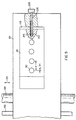
- printer 10 also comprises a first embodiment print head body 60 disposed adjacent to platen roller 40. Slidably received in a cavity 63 formed in print head body 60 is a nozzle block 65 having a plurality of aligned printing elements, such as aligned ink channels 70 of number "N" (only four of which are shown). Each channel 70 terminates in a channel outlet 75, opposite receiver 30. In addition, each channel 70, which is adapted to hold an ink body 77 therein, is defined by a pair of oppositely disposed parallel side walls 79a and 79b.
- nozzle block 65 Attached, such as by a suitable adhesive, to nozzle block 65 is a cover plate 80 having a plurality of aligned side-by-side nozzle orifices 90 formed therethrough colinearly aligned with respective ones of channel outlets 75. Adjacent ones of orifices 90 have a center-to-center constant predetermined pitch "P" (as shown).
- P center-to-center constant predetermined pitch
- nozzle block 65 may be a "piezoelectric ink jet” nozzle block formed of a piezoelectric material, such as lead zirconium titanate (PZT). Such a piezoelectric material is mechanically responsive to electrical stimuli so that side walls 79a/b simultaneously inwardly deform when electrically stimulated. When side walls 79a/b simultaneously inwardly deform, volume of channel 70 decreases to squeeze ink droplet 105 from channel 70.
- nozzle block 65 may be a "continuous ink jet” nozzle block, wherein ejection of ink droplet 105 is caused by a pressure induced in ink body 77.
- a transport mechanism is connected to print head body 60 for reciprocating print head body 60 between a first position 115a thereof and a second position 115b (shown in phantom).
- print head body 60 slidably engages an elongate guide rail 120, which guides print head body 60 parallel to platen roller 40 while print head body 60 is reciprocated across width W in a direction as shown by a double headed second arrow 125.
- transport mechanism 110 also comprises a drive belt 130 attached to print head body 60 for reciprocating print head body 60 between first position 115a and second position 115b, in the manner described presently.
- a reversible drive belt motor 140 engages belt 130, such that belt 130 reciprocates in order that print head body 60 reciprocates along width W of receiver 30.
- an encoder strip 150 coupled to print head body 60 monitors position of print head body 60 as print head body 60 reciprocates between first position 115a and second position 115b.
- a controller 160 is connected to platen roller motor 50, drive belt motor 140, encoder strip 150 and print head body 60 for controlling operation thereof, so that image 20 suitably forms on receiver 30.
- a controller may be a Model CompuMotor controller available from Parker Hannifin, Incorporated located in Rohnert Park, California.
- Spring-loaded actuator 165 comprises an elastic spring 170 coupled to nozzle block 65 for slidably biasing nozzle block 65 in cavity 63 along a predetermined displacement distance "P 1 " less than pitch P, for reasons described hereinbelow.
- P 1 n P k , where,
- a motor 180 is preferably connected to spring 170, such as by means of a movable base 185, for exerting a force on spring 170, so that spring 170 exerts a force on nozzle block 65.
- motor 180 can include a suitable encoder capable of monitoring the amount of motor rotation.
- Nozzle block 65 slidably advances in cavity 63 in response to the force exerted on nozzle block 65 by spring 170.
- a blind bore 193 having a closed end 195 is formed in print head body 60, which blind bore 193 is sized to slidably receive an elongate extension 197 of nozzle block 65.
- Motor 180 is operated to exert a force on spring 170 to displace nozzle block 65 a predetermined distance P 1 .
- Screw-driven actuator 200 comprises a lead screw 210 having external threads thereon, which lead screw 210 threadably engages an internally threaded bore 215 formed in nozzle block 65.
- a reversible motor 200 is preferably connected to lead screw 210 for rotating lead screw 210, so that lead screw 210 slidably advances nozzle block 65 in cavity 63 while lead screw 210 rotates.
- a counter-sink bore 225 may be formed in print head body 60, which counter-sink bore 225 is sized to receive lead-screw 210.
- nozzle block 65 precisely moves nozzle block 65 in cavity 63 along predetermined distance "P 1 ".
- advancement of nozzle block 65 in cavity 63 is a function of the amount of rotation of lead-screw, pitch of the external threads of lead screw 210 and pitch of the internal threads of counter-sink bore 225.
- a person or ordinary skill in the art may predetermine amount of rotation of lead-screw, pitch of the external threads of lead screw 210 and pitch of internal threads of counter-sink bore 225 that will precisely move nozzle block 65 the predetermined distance P 1 .
- nozzle block 65 can thereafter be caused to retreat in cavity 63 the same distance P 1 by rotating lead screw 210 in a direction opposite its initial rotation.
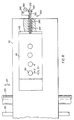
- Hydraulic actuator 230 comprises an enclosure 240 having a surface 245 thereon and defining a chamber 250 therein.
- a bore 253 extends from chamber 250 to surface 245 and is sized to slidably receive an elongate piston rod 255 for reasons described presently.
- a movable piston 260 is slidably disposed in chamber 240, which piston 260 has an anterior face 263 and a posterior face 265.
- Piston rod 255 has a first end portion 267 thereof connected to anterior face 263 and a second end portion 269 thereof attached to nozzle block 65.
- a reversible-flow pump 270 is in fluid communication with chamber 250 for pumping a hydraulic liquid (e.g., water, oil, or the like) from a liquid reservoir 280 and into chamber 250.
- a hydraulic liquid e.g., water, oil, or the like
- posterior face 265 of piston 260 is pressurized and will slidably move in chamber 250 in a direction toward nozzle block 65.
- piston rod 255 will slidably move in bore 257 to a like extent because piston rod 255 is connected to piston 260.
- nozzle block 65 will slidably move in cavity 63 to a like extent because piston rod 255 is also connected to nozzle block 65.
- nozzle block 65 advances only the predetermined distance P 1 .
- pump 270 is cause to cease operation.
- Elastic spring 170 which has a predetermined spring constant, is also provided in this embodiment of the displacement mechanism. That is, elastic spring 170, which is coupled to nozzle block 65, exerts a force that slidably biases nozzle block 65 in cavity 63, such that nozzle block 65 returns to its initial starting point after pump 270 ceases operation.
- spring 170 is selected such that force of spring 170 exerted on nozzle block 65 is greater than pressure on posterior face 265 when pump 270 ceases operation and also due to pump 270 allowing reverse flow of liquid therethrough. Advancement of nozzle block 65 in cavity 63 is limited by amount of pressurization of posterior face 265 and the spring constant of spring 170. Thus, a person of ordinary skill in the art may, without undue experimentation, predetermine the appropriate amount of pressurization of posterior face 265 and the spring constant so that nozzle block 65 moves the predetermined distance P 1 .
- a fourth embodiment displacement mechanism such as a pneumatic actuator generally referred to as 290.
- This fourth embodiment of the displacement mechanism is substantially identical to the third embodiment of the displacement mechanism, except that liquid reservoir 280 is absent and pump 270 pumps a gas (e.g., air) into chamber 250 rather than a liquid to achieve similar results.
- a gas e.g., air
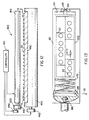
- Piezoelectric actuator 300 comprises a shaft 310 slidably disposed in bore 257.
- Shaft 310 is made of piezoelectric material, such as lead zirconium titanate (PZT), capable of deforming in a preferred direction in response to electrical stimulus applied thereto.
- PZT lead zirconium titanate
- the piezoelectric material of shaft 310 is selected such that when the electrical stimulus is applied thereto, it will elongate in direction of nozzle block 65 and become narrower.
- first electrode 320 is connected to shaft 310, which first electrode 320 is also connected to a voltage source 330 for applying voltage to shaft 310.
- a second electrode 340 is also connected to shaft 310, which second electrode 340 is connected to ground potential, as at point 345.
- first electrode 320 may extend centrally in shaft 310 and second electrode 340 may be disposed in bore 257 and surround shaft 310.
- As voltage is applied to first electrode 320 an electric field is established between first electrode 320 and second electrode 340 and thus this electric field is established in shaft 310 so that shaft 310 elongates.
- Shaft 310 will preferentially slidably elongate in bore 257 toward nozzle block 65 because movement of shaft 310 is constrained at an end thereof farthest away from nozzle block 65 by presence of an immovable stop 347 rigidly connected to shaft 310.
- the other end of shaft 310 is free to move because this other end of shaft 310 is connected to nozzle block 65 and nozzle block 65 is slidably movable in cavity 63.
- shaft 310 becomes shorter for returning nozzle block 65 to its initial position. Advancement of nozzle block 65 in cavity 63 is limited by amount of voltage applied to shaft 310.
- a person of ordinary skill in the art may, without undue experimentation, predetermine the appropriate amount of voltage so that nozzle block 65 moves the predetermined distance P 1 .
- a suitable piezoelectric actuator is available from Polytec PI, Incorporated located in Auburn, Massachusetts.
- an area 350 of image 20 comprises a plurality of marks 360 formed into a plurality of rows 365a/b/c/d/e by ink droplets 105 ejected onto receiver 30 by ink ejection channels 70.
- Adjacent ones of marks 360 have predetermined pitch P because channels 70, from which droplets 105 have been ejected, have predetermined pitch P.
- travel of print head body 60 is in direction of a third arrow 367 and droplets 105 are ejected by print head body 60 at a constant spacing "D" to form rows 365a/b/c/d/e.
- this initial position of nozzle block 65, and channels 70 associated therewith, define a first spatial resolution of marks 360.
- nozzle block 65 and thus ink ejection channels 70, are slidably moved in cavity 63 the predetermined distance P 1 less than predetermined pitch P, as previously described. This is done to increase spatial resolution of image 20. Movement of nozzle block 65 is obtained by use of any of the previously mentioned embodiments of the displacement mechanism. That is, channels 70 are enabled so that droplets 105 are ejected by channels 70 when nozzle block 65 resides in its initial position. The marks 360 formed when nozzle block 65 is in its initial position define a first spatial resolution of the marks 360. Thereafter, nozzle block 65 is moved predetermined distance P 1 and again enabled to eject additional droplets 105 to form additional marks 360 (shown in phantom). Thus, when channels 70 form additional marks 360 at predetermined distance P 1 , all marks 360 will now define a second spatial resolution greater than the first spatial resolution. It is in this manner that spatial resolution of image 20 is increased.
- Second printer 400 is a so-called "page-width" printer capable of printing across width W of receiver 30 without reciprocating across width W. That is, printer 400 comprises a second embodiment print head body 410 of length substantially equal to width W. Connected to print head body 410 is a carriage 420 adapted to carry print head body 410 in direction of first arrow 55. In this regard, carriage 420 slidably engages an elongate slide member 430 extending parallel to length of receiver 30 in direction of first arrow 55.
- a first motor 440 is connected to carriage 420 for operating carriage 420 so that carriage 420 slides along slide member 430 in direction of first arrow 55.
- print head body 410 also travels in direction of first arrow 55 because print head body 410 is connected to carriage 420.
- print head body 410 is capable of printing a plurality of images 20 (as shown) in a single printing pass along a length of receiver 30.
- a first feed roller 450 engages receiver 30 for feeding receiver 30 in direction of first arrow 55 after images 20 have been printed.
- a second motor 460 engages first feed roller 450 for rotating first feed roller 450, so that receiver 30 feeds in direction of first arrow 55.
- a second feed roller 470 spaced-apart from first feed roller 450, may also engage receiver 30 for feeding receiver 30 in direction of first arrow 55.
- third motor 480 synchronized with second motor 460, engages second feed roller 470 for rotating second feed roller 470, so that receiver 30 feeds in direction of first arrow 55.
- a support member such as a stationary platen 490, for supporting receiver 30 thereon as receiver feeds from first feed roller 450 to second feed roller 470.
- controller 160 is connected to print head body 410, first motor 440, second motor 460 and third motor 480 for controlling operation thereof in order to suitably form image 20 on receiver 30.
- second embodiment print head body 410 includes a plurality of nozzle blocks 65 off-set one from another, so that nozzle blocks 65 obtain an interleaved configuration (as shown). More specifically, end portions of individual ones of adjacent nozzle blocks 65 overlap, so that orifices 90 laying in such overlapping regions are capable of addressing the same location on receiver 30.
- Print head body 410 is capable of translational motion in direction of first arrow 55 and housing 500 is capable of displacement by any desired distance perpendicular to direction of motion of print heady body 410.
- the plurality of nozzle blocks 65 may be housed in a housing 500 capable of being moved in the manner described hereinabove in connection with first embodiment print head body 60.
- an advantage of the present invention is that image 20 obtains increased spatial resolution. This is so because additional marks 360 are formed due to movement of nozzle block 65, which additional marks are intermediate marks that are formed when nozzle block 65 is in its initial position relative to print head body 60.
- Another advantage of the present invention is that fault tolerance of the printer is increased. This is so because the same dot location on receiver 30 can now be addressed by different nozzles 90. That is, the dot location can be addressed while nozzle block 65 is in its initial position relative to print head body 60 and again addressed after nozzle block 65 has moved predetermined distance nP. In this manner, a selected one of nozzles 90 can compensate for an inoperative nozzle 90.
- Still another advantage of the present invention is that spatial resolution of the image is increased in a cost-effective manner. This is so because all available nozzles 90 are used for printing (i.e., no nozzles are intentionally disabled). Printer fabrication costs are also reduced because, at least with respect to second printer 400, receiver 30 does not move during printing of a plurality of images 20. This obviates need for complicated electronic circuitry and an expensive transport mechanism to advance receiver 30 the distance D in order to print each row of dots 360 comprising image 20.
- the displacement mechanism may take any one of several forms, such as an electromagnetic device.
- nozzle block 65 is at least in part made of a metal capable of moving under influence of a magnetic field suitably generated by an electromagnet.
- an ink jet printer capable of increasing spatial resolution of a plurality of marks to be printed thereby and method of assembling the printer.
Landscapes
- Ink Jet (AREA)
- Particle Formation And Scattering Control In Inkjet Printers (AREA)
- Dot-Matrix Printers And Others (AREA)
Applications Claiming Priority (2)
| Application Number | Priority Date | Filing Date | Title |
|---|---|---|---|
| US188574 | 1998-11-09 | ||
| US09/188,574 US6089696A (en) | 1998-11-09 | 1998-11-09 | Ink jet printer capable of increasing spatial resolution of a plurality of marks to be printed thereby and method of assembling the printer |
Publications (2)
| Publication Number | Publication Date |
|---|---|
| EP1000757A2 true EP1000757A2 (fr) | 2000-05-17 |
| EP1000757A3 EP1000757A3 (fr) | 2000-10-04 |
Family
ID=22693718
Family Applications (1)
| Application Number | Title | Priority Date | Filing Date |
|---|---|---|---|
| EP99203567A Withdrawn EP1000757A3 (fr) | 1998-11-09 | 1999-10-29 | Une imprimante à jet d'encre pouvant augmenter la résolution spatiale du marquage à imprimer et procédé d'assemblage de cette imprimante |
Country Status (3)
| Country | Link |
|---|---|
| US (1) | US6089696A (fr) |
| EP (1) | EP1000757A3 (fr) |
| JP (1) | JP2000168065A (fr) |
Cited By (2)
| Publication number | Priority date | Publication date | Assignee | Title |
|---|---|---|---|---|
| US6663222B2 (en) | 2000-12-22 | 2003-12-16 | Agfa-Gevaert | Ink jet printer with nozzle arrays that are moveable with respect to each other |
| CH696165A5 (de) * | 2002-05-10 | 2007-01-31 | Textilma Ag | Tintenstrahl Druckeranlage zum fortlaufenden Bedrucken eines textilen Flächengebildes. |
Families Citing this family (14)
| Publication number | Priority date | Publication date | Assignee | Title |
|---|---|---|---|---|
| GB9818025D0 (en) * | 1998-08-18 | 1998-10-14 | Neopost Ltd | Print head transport mechanism |
| US6786658B2 (en) * | 2000-05-23 | 2004-09-07 | Silverbrook Research Pty. Ltd. | Printer for accommodating varying page thicknesses |
| US6526658B1 (en) | 2000-05-23 | 2003-03-04 | Silverbrook Research Pty Ltd | Method of manufacture of an ink jet printhead having a moving nozzle with an externally arranged actuator |
| US7052117B2 (en) | 2002-07-03 | 2006-05-30 | Dimatix, Inc. | Printhead having a thin pre-fired piezoelectric layer |
| KR100445118B1 (ko) * | 2002-09-17 | 2004-08-21 | 삼성전자주식회사 | 잉크젯 프린터의 프린트 헤드 위치조절 장치 |
| JP4563019B2 (ja) * | 2002-11-07 | 2010-10-13 | オセ−テクノロジーズ ビーブイ | プリントキャリッジアセンブリ及びそのアセンブリにプリンタヘッドホルダーを設置するための方法 |
| JP2005081713A (ja) * | 2003-09-09 | 2005-03-31 | Konica Minolta Holdings Inc | インクジェットプリンタにおける記録ヘッドの傾き調整装置 |
| US8491076B2 (en) | 2004-03-15 | 2013-07-23 | Fujifilm Dimatix, Inc. | Fluid droplet ejection devices and methods |
| US7281778B2 (en) | 2004-03-15 | 2007-10-16 | Fujifilm Dimatix, Inc. | High frequency droplet ejection device and method |
| EP1836056B1 (fr) | 2004-12-30 | 2018-11-07 | Fujifilm Dimatix, Inc. | Impression a jet d'encre |
| US20080122882A1 (en) * | 2006-11-29 | 2008-05-29 | Great Computer Corporation. | Method for printing an article by using a UV ink-jet printer and a printing module for implementing the method |
| US7988247B2 (en) | 2007-01-11 | 2011-08-02 | Fujifilm Dimatix, Inc. | Ejection of drops having variable drop size from an ink jet printer |
| JP5412306B2 (ja) * | 2010-01-27 | 2014-02-12 | 株式会社ミヤコシ | インクジェット印字装置 |
| US9180684B2 (en) * | 2013-12-18 | 2015-11-10 | Xerox Corporation | Autofocus LED print head mechanism |
Citations (2)
| Publication number | Priority date | Publication date | Assignee | Title |
|---|---|---|---|---|
| US4069486A (en) | 1976-06-28 | 1978-01-17 | International Business Machines Corporation | Single array ink jet printer |
| US4401991A (en) | 1981-10-08 | 1983-08-30 | International Business Machines Corporation | Variable resolution, single array, interlace ink jet printer |
Family Cites Families (13)
| Publication number | Priority date | Publication date | Assignee | Title |
|---|---|---|---|---|
| US4063254A (en) * | 1976-06-28 | 1977-12-13 | International Business Machines Corporation | Multiple array printer |
| US4362406A (en) * | 1979-07-30 | 1982-12-07 | International Business Machines Corp. | Dot matrix print head |
| JPS5628882A (en) * | 1979-08-17 | 1981-03-23 | Ricoh Co Ltd | Recorder |
| US4675696A (en) * | 1982-04-07 | 1987-06-23 | Canon Kabushiki Kaisha | Recording apparatus |
| US4593295A (en) * | 1982-06-08 | 1986-06-03 | Canon Kabushiki Kaisha | Ink jet image recording device with pitch-shifted recording elements |
| IT1199923B (it) * | 1985-12-23 | 1989-01-05 | Olivetti & Co Spa | Stampante a punti a getto d'inchiostro con testina multipla regolabile |
| US4774529A (en) * | 1987-02-26 | 1988-09-27 | Xerox Corporation | Repositionable marking head for increasing printing speed |
| US5241325A (en) * | 1991-10-31 | 1993-08-31 | Hewlett-Packard Company | Print cartridge cam actuator linkage |
| US5880757A (en) * | 1991-11-04 | 1999-03-09 | Hewlett-Packard Company | Print resolution enhancement by adjusting printhead position |
| DE69412805T2 (de) * | 1994-07-18 | 1999-03-11 | Oce-Nederland B.V., Venlo | Drucker mit einem beweglichen Druckkopf |
| US5598192A (en) * | 1995-06-08 | 1997-01-28 | Xerox Corporation | Thermal ink jet printhead with extended print capability |
| US5829895A (en) * | 1995-12-27 | 1998-11-03 | Pitney Bowes Inc. | Method for printing an image indicative of value such as a postal indicia |
| US5870117A (en) * | 1997-01-21 | 1999-02-09 | Xerox Corporation | Liquid ink printer including a camming printhead to enable increased resolution printing |
-
1998
- 1998-11-09 US US09/188,574 patent/US6089696A/en not_active Expired - Lifetime
-
1999
- 1999-10-29 EP EP99203567A patent/EP1000757A3/fr not_active Withdrawn
- 1999-11-08 JP JP11317201A patent/JP2000168065A/ja active Pending
Patent Citations (2)
| Publication number | Priority date | Publication date | Assignee | Title |
|---|---|---|---|---|
| US4069486A (en) | 1976-06-28 | 1978-01-17 | International Business Machines Corporation | Single array ink jet printer |
| US4401991A (en) | 1981-10-08 | 1983-08-30 | International Business Machines Corporation | Variable resolution, single array, interlace ink jet printer |
Cited By (2)
| Publication number | Priority date | Publication date | Assignee | Title |
|---|---|---|---|---|
| US6663222B2 (en) | 2000-12-22 | 2003-12-16 | Agfa-Gevaert | Ink jet printer with nozzle arrays that are moveable with respect to each other |
| CH696165A5 (de) * | 2002-05-10 | 2007-01-31 | Textilma Ag | Tintenstrahl Druckeranlage zum fortlaufenden Bedrucken eines textilen Flächengebildes. |
Also Published As
| Publication number | Publication date |
|---|---|
| US6089696A (en) | 2000-07-18 |
| EP1000757A3 (fr) | 2000-10-04 |
| JP2000168065A (ja) | 2000-06-20 |
Similar Documents
| Publication | Publication Date | Title |
|---|---|---|
| US6089696A (en) | Ink jet printer capable of increasing spatial resolution of a plurality of marks to be printed thereby and method of assembling the printer | |
| DE69605586T2 (de) | Tintenstrahlaufzeichnungskopf | |
| EP0787587B1 (fr) | Dispositif d'impression par jet encre | |
| US5870117A (en) | Liquid ink printer including a camming printhead to enable increased resolution printing | |
| EP0528648B2 (fr) | Mécanisme d'actionnement allongé pour une tête d'impression à jet d'encre à haute densité | |
| US20030103095A1 (en) | Ink jet device | |
| JPH0452215B2 (fr) | ||
| US20090189958A1 (en) | Liquid ejection head and image forming apparatus | |
| DE60303847T2 (de) | Vorrichtung zum Ausstoss sehr kleiner Tröpfchen | |
| DE69021445T2 (de) | Tintenstrahlkopf und Gerät für seine Anwendung. | |
| EP2296898B1 (fr) | Impression par jet d encre | |
| US20180111384A1 (en) | Valve | |
| JPH0694014B2 (ja) | 小型高速スプレ−ガン | |
| US7234789B2 (en) | Apparatus for ejecting droplets, actuator controller used in the apparatus, and method for controlling the actuator | |
| DE69127005T2 (de) | Aufzeichnungsvorrichtung | |
| US6074046A (en) | Printer apparatus capable of varying direction of an ink droplet to be ejected therefrom and method therefor | |
| US6318829B1 (en) | Ink jet recording apparatus and ink ejection control method | |
| DE60027684T2 (de) | Neues Antriebsverfahren eines Druckwagens eines Tintenstrahldruckers | |
| JPH05116380A (ja) | 記録装置 | |
| DE60103947T2 (de) | Druckkopf-Substrat mit Tintentropfenerzeugern aufgeteilt in Gruppen die beide Seitenkanten eines Tintenzuführkanals umfassen | |
| DE60310299T2 (de) | Tintenausstossvorrichtung | |
| US7744189B2 (en) | Liquid ejecting apparatus | |
| JP2002127403A (ja) | インクジェットプリントヘッドの作動方法 | |
| US20030179258A1 (en) | Methods and apparatus for reducing or minimizing satellite defects in fluid ejector systems | |
| DE10227586A1 (de) | System und Verfahren zum Optimieren einer Tintentrocknungszeit durch mehrere beabstandete Druckköpfe |
Legal Events
| Date | Code | Title | Description |
|---|---|---|---|
| PUAI | Public reference made under article 153(3) epc to a published international application that has entered the european phase |
Free format text: ORIGINAL CODE: 0009012 |
|
| AK | Designated contracting states |
Kind code of ref document: A2 Designated state(s): DE FR GB |
|
| AX | Request for extension of the european patent |
Free format text: AL;LT;LV;MK;RO;SI |
|
| PUAL | Search report despatched |
Free format text: ORIGINAL CODE: 0009013 |
|
| AK | Designated contracting states |
Kind code of ref document: A3 Designated state(s): AT BE CH CY DE DK ES FI FR GB GR IE IT LI LU MC NL PT SE |
|
| AX | Request for extension of the european patent |
Free format text: AL;LT;LV;MK;RO;SI |
|
| RIC1 | Information provided on ipc code assigned before grant |
Free format text: 7B 41J 2/505 A, 7B 41J 2/51 B |
|
| 17P | Request for examination filed |
Effective date: 20010322 |
|
| AKX | Designation fees paid |
Free format text: DE FR GB |
|
| STAA | Information on the status of an ep patent application or granted ep patent |
Free format text: STATUS: THE APPLICATION HAS BEEN WITHDRAWN |
|
| 18W | Application withdrawn |
Effective date: 20051024 |