EP1000793B1 - Transmission pour véhicules - Google Patents
Transmission pour véhicules Download PDFInfo
- Publication number
- EP1000793B1 EP1000793B1 EP99308952A EP99308952A EP1000793B1 EP 1000793 B1 EP1000793 B1 EP 1000793B1 EP 99308952 A EP99308952 A EP 99308952A EP 99308952 A EP99308952 A EP 99308952A EP 1000793 B1 EP1000793 B1 EP 1000793B1
- Authority
- EP
- European Patent Office
- Prior art keywords
- drive shaft
- wheel
- gear
- differential
- hst
- Prior art date
- Legal status (The legal status is an assumption and is not a legal conclusion. Google has not performed a legal analysis and makes no representation as to the accuracy of the status listed.)
- Expired - Lifetime
Links
- 230000007246 mechanism Effects 0.000 claims description 73
- 230000005540 biological transmission Effects 0.000 claims description 69
- 238000006073 displacement reaction Methods 0.000 claims description 15
- 230000003247 decreasing effect Effects 0.000 claims description 8
- 230000008878 coupling Effects 0.000 claims description 3
- 238000010168 coupling process Methods 0.000 claims description 3
- 238000005859 coupling reaction Methods 0.000 claims description 3
- 238000010586 diagram Methods 0.000 description 8
- 239000000969 carrier Substances 0.000 description 3
- 238000010276 construction Methods 0.000 description 3
- 230000009467 reduction Effects 0.000 description 3
- 230000001771 impaired effect Effects 0.000 description 2
- 239000000463 material Substances 0.000 description 2
- 230000009471 action Effects 0.000 description 1
- 230000008901 benefit Effects 0.000 description 1
- 238000004519 manufacturing process Methods 0.000 description 1
Images






Classifications
-
- B—PERFORMING OPERATIONS; TRANSPORTING
- B60—VEHICLES IN GENERAL
- B60K—ARRANGEMENT OR MOUNTING OF PROPULSION UNITS OR OF TRANSMISSIONS IN VEHICLES; ARRANGEMENT OR MOUNTING OF PLURAL DIVERSE PRIME-MOVERS IN VEHICLES; AUXILIARY DRIVES FOR VEHICLES; INSTRUMENTATION OR DASHBOARDS FOR VEHICLES; ARRANGEMENTS IN CONNECTION WITH COOLING, AIR INTAKE, GAS EXHAUST OR FUEL SUPPLY OF PROPULSION UNITS IN VEHICLES
- B60K17/00—Arrangement or mounting of transmissions in vehicles
- B60K17/04—Arrangement or mounting of transmissions in vehicles characterised by arrangement, location or kind of gearing
- B60K17/10—Arrangement or mounting of transmissions in vehicles characterised by arrangement, location or kind of gearing of fluid gearing
- B60K17/105—Units comprising at least a part of the gearing and a torque-transmitting axle, e.g. transaxles
-
- B—PERFORMING OPERATIONS; TRANSPORTING
- B60—VEHICLES IN GENERAL
- B60K—ARRANGEMENT OR MOUNTING OF PROPULSION UNITS OR OF TRANSMISSIONS IN VEHICLES; ARRANGEMENT OR MOUNTING OF PLURAL DIVERSE PRIME-MOVERS IN VEHICLES; AUXILIARY DRIVES FOR VEHICLES; INSTRUMENTATION OR DASHBOARDS FOR VEHICLES; ARRANGEMENTS IN CONNECTION WITH COOLING, AIR INTAKE, GAS EXHAUST OR FUEL SUPPLY OF PROPULSION UNITS IN VEHICLES
- B60K17/00—Arrangement or mounting of transmissions in vehicles
- B60K17/34—Arrangement or mounting of transmissions in vehicles for driving both front and rear wheels, e.g. four wheel drive vehicles
- B60K17/356—Arrangement or mounting of transmissions in vehicles for driving both front and rear wheels, e.g. four wheel drive vehicles having fluid or electric motor, for driving one or more wheels
-
- B—PERFORMING OPERATIONS; TRANSPORTING
- B62—LAND VEHICLES FOR TRAVELLING OTHERWISE THAN ON RAILS
- B62D—MOTOR VEHICLES; TRAILERS
- B62D11/00—Steering non-deflectable wheels; Steering endless tracks or the like
- B62D11/02—Steering non-deflectable wheels; Steering endless tracks or the like by differentially driving ground-engaging elements on opposite vehicle sides
- B62D11/06—Steering non-deflectable wheels; Steering endless tracks or the like by differentially driving ground-engaging elements on opposite vehicle sides by means of a single main power source
- B62D11/10—Steering non-deflectable wheels; Steering endless tracks or the like by differentially driving ground-engaging elements on opposite vehicle sides by means of a single main power source using gearings with differential power outputs on opposite sides, e.g. twin-differential or epicyclic gears
- B62D11/14—Steering non-deflectable wheels; Steering endless tracks or the like by differentially driving ground-engaging elements on opposite vehicle sides by means of a single main power source using gearings with differential power outputs on opposite sides, e.g. twin-differential or epicyclic gears differential power outputs being effected by additional power supply to one side, e.g. power originating from secondary power source
- B62D11/18—Steering non-deflectable wheels; Steering endless tracks or the like by differentially driving ground-engaging elements on opposite vehicle sides by means of a single main power source using gearings with differential power outputs on opposite sides, e.g. twin-differential or epicyclic gears differential power outputs being effected by additional power supply to one side, e.g. power originating from secondary power source the additional power supply being supplied hydraulically
-
- B—PERFORMING OPERATIONS; TRANSPORTING
- B62—LAND VEHICLES FOR TRAVELLING OTHERWISE THAN ON RAILS
- B62D—MOTOR VEHICLES; TRAILERS
- B62D9/00—Steering deflectable wheels not otherwise provided for
Definitions
- the present invention relates to a driving apparatus for use in four-wheel drive vehicles for transmitting power from a drive source to steerable wheels and nonsteerable wheels via a main HST (hydraustatic transmission).
- a main HST hydroaustatic transmission
- a driving apparatus having a one-way clutch provided in the path of power transmission to the steerable wheels for transmitting a driving power to the steerable wheel and also permitting the steerable wheel to rotate at a higher speed than the nonsteerable wheel when the vehicle is turned
- a driving apparatus wherein the path of power transmission to the steerable wheels is provided with a gear transmission unit for giving an increased speed.
- the gear transmission unit is brought out of operation when the vehicle is advanced straight, or is operated to rotate the steerable wheel at a higher speed than the nonsteerable wheel when the vehicle is turned.
- the driving apparatus (1) has the drawback the vehicle fails to fully exhibit the performance of four-wheel drive since the nonsteerable wheels only are driven as in a two-wheel drive vehicle when the vehicle is turned. This entails another drawback that the vehicle is impaired in running performance when turning with a small radius since the nonsteerable wheels only are driven for turning.
- the steerable wheel is rotatable only at two speeds, i.e., a high speed and the same speed as the nonsteerable wheel.
- the difference between the steerable wheel and the nonsteerable wheel in turning radius is proportional to the steering angle of the steering wheel to be handled by a driver.
- the driving apparatus (2) which affords only two different rotational speeds to the steerable wheels fails to fully preclude the steerable wheels from skidding.
- the driving apparatus is capable of providing two different speeds, i.e., a high speed and the same speed, for the steerable wheel, it is impossible to increase the rotational speed difference between the steerable wheel and the nonsteerable wheel because the rotational speed of the nonsteerable wheel is constant. If the vehicle is turned with a small radius, i.e., if the difference between the steerable wheel and the non and the nonsteerable wheel in turning radius is great, it is difficult to obtain such a speed difference as to offset the radius difference.
- a driving apparatus similar to the apparatus 1 and having a transmission unit for giving an increased speed which unit comprises a pair of pulleys and a belt reeved around the pulleys, the pulleys being variable in effective diameter according to the rotation angle of the steering wheel at the driver's seat.
- the apparatus also encounters difficulty in increasing the rotational speed difference between the steerable wheel and the nonsteerable wheel since the rotational speed of the nonsteerable wheel is constant.
- the resembling problem occurs. That is, the turning radius of front ground wheel and rear ground wheel is usually different from each other. Therefore, the adjustment between the rotational speed of the front wheels and the rear wheels is necessary.
- GB-A-2274320 discloses an electromagnetic clutch driven steerable drive axle for a four wheel drive vehicle.
- US-A-4886142 defining the preamble of claims 1 and 7, discloses a hydraulic four-wheel drive apparatus for driving a hydraulic motor with four wheels: steering wheels and driving wheels, in which the steering wheels are driven by a variable capacity motor and the driving wheels are driven by a fixed capacity motor.
- An object of the present invention which has been accomplished to overcome the foregoing problems, is to provide a driving apparatus for use in four-wheel drive vehicles, the apparatus being adapted to effectively prevent the steerable wheels from skidding while transmitting power to the steerable wheels when turning the vehicle.
- a driving apparatus for a vehicle for transmitting power via a main HST from a drive source installed in a body of the vehicle to a first pair of driving wheels and a second pair of driving wheels, the pairs of wheels being positioned at the front and rear of the vehicle body and at least one pair of the pairs of driving wheels being steerable, the driving apparatus comprising:
- the apparatus is further adapted for a vehicle in which the first pair of wheels are steerable and the second pair of wheels are nonsteerable, the first drive shaft and the second drive shaft are a steerable wheel drive shaft and a nonsteerable wheel drive shaft respectively, and the first planetary gear unit and the second planetary gear unit are a steerable wheel planetary gear unit and a nonsteerable wheel planetary gear unit respectively.
- the steerable wheel drive shaft and the nonsteerable wheel drive shaft are arranged approximately on a common axis and spaced apart from each other at opposed ends thereof, the main drive shaft is disposed between the opposed ends of the steerable wheel drive shaft and the nonsteerable wheel drive shaft on the same axis as the two shafts, the steerable wheel planetary gear unit has a first sun gear mounted on the main drive shaft, a first outer wheel surrounding the first sun gear, a first inner gear provided on an inner periphery of the first outer wheel, first planetary gears arranged between the first sun gear and the first inner gear, and a first carrier supported on the steerable wheel drive shaft nonrotatably relative thereto and rotatable with revolutions of the first planetary gears, and the nonsteerable wheel planetary gear unit has a second sun gear mounted on the main deive shaft, a second outer wheel surrounding the second sun gear, a second inner gear provided on an inner periphery of the second outer wheel, second planetary gears arranged between
- the differential power transmission mechanism receives the rotational output from the differential HST and adjusts rotational speeds of the first outer wheel and the second outer wheel respectively in opposite directions to each other, the differential HST is adapted not to output the rotational drive force when the vehicle is advanced straight and to output the rotational drive force with a number of revolutions in accordance with the steering angle of the steering wheel when the vehicle is turned, the differential power transmission mechanism is adapted to adjust the rotational speed of the first outer wheel in the same direction as the rotational direction of the first sun gear rotated by the main HST and to adjust the rotational speed of the second outer wheel in a direction opposite to the rotational direction of the second sun gear rotated by the main HST.
- the differential HST has a hydraulic pump and a hydraulic motor, at least one of the hydraulic pump and the hydraulic motor being of the variable displacement type which is variable in displacement by operating a displacement altering member
- the differential unit further comprises a link mechanism coupling a steering wheel to be handled by a driver to the displacement altering member, and the link mechanism is adapted to reduce approximately to zero the discharge rate of one of the hydraulic pump and the hydraulic motor which has the displacement altering member when the steering wheel is directed to advance the vehicle straight and to increase the discharge rate as the steering angle of the steering wheel increases when the steering wheel is directed to turn the vehicle.
- the driving power transmission mechanism and the differential power transmission mechanism are each a power transmission gear mechanism.
- a driving apparatus for a vehicle for transmitting power via a main HST from a drive source installed in a body of the vehicle to a first pair of driving wheels and a second pair of driving wheels, the pairs of wheels being positioned at the front and rear of the vehicle body and at least one pair of the pairs of driving wheels being steerable, the driving apparatus comprising:
- FIG. 1 is a fragmentary plan view of a vehicle 100 comprising a driving apparatus 1 embodying the invention.
- the driving apparatus of the embodiment is adapted for use in four-wheel drive vehicles wherein power is delivered from a drive source 60 installed in the body of the vehicle to a main HST 50, the output of which is transmitted to rear wheels serving as steeling wheels and to the non-steerable wheels, i.e. front wheels as shown in FIG. 1.
- the apparatus comprises a front wheel drive shaft and a rear wheel drive shaft for outputting a front wheel drive force and rear wheel drive force respectively, a transmission unit for transmitting the output of the main HST to the front wheel drive axle and the rear wheel drive axle, and a differential unit for reducing the rotational speed of the front wheel drive axle and increasing the rotational speed of the rear wheel drive axle according to the steeling angle of the rear wheels when the rear wheels are turned.
- Indicated at 75 and 76 in the drawing are a front axle and a rear axle, respectively.
- Indicated at 70 is a rear wheel drive unit connected to the rear axle 76 by an axle coupling for outputting a rear axle drive force.
- Further indicated at 80 is a PTO unit for delivering a drive force to a mower or the like.
- Indicated at 31 is a differential HST, and at 32 and 35 are a hydraulic pump and hydraulic motor, respectively, of the differential HST.
- FIG. 2 is a plan view in section of the main HST and the surroundings thereof.
- the main HST 50 has a hydraulic pump 52 and a hydraulic motor 55 at least one of which is of the variable displacement type, and a housing 51 for enclosing the pump and the motor.
- the hydraulic pump 52 is of the variable displacement type
- the hydraulic motor 55 is a fixed displacement motor.
- the housing 51 has a body 51a and an extension 51b extending outward from the body 51a widthwise of the vehicle.
- the pump 52 and the motor 55 are accommodated in the housing body 51a, while the PTO unit 80 is enclosed in the housing extension 51b.
- the housing body 51a is open at its front side and closed with a rear wall at its rear side, while the extension 51b is closed with a front wall at its front side and open at its rear side.
- the front opening of the body 51a is closed with a hydraulic block 85
- the rear opening of the extension 51b is closed with a closure member 86.
- the hydraulic block 85 needs to have a considerable thickness to ensure a quantity of oil, the increase in the length of the block 85 widthwise of the vehicle requires an increased amount of material.
- the mold for the body 51a having the front opening can be removed toward the front, and the mold for the extension 51b having the rear opening is removable rearward, with the result that the housing can be cast easily.
- the hydraulic pump 52 has a pump shaft 53 extending longitudinally of the vehicle body.
- the pump shaft 53 has a rear end projecting rearward from the housing 51 and connected to the output shaft of the drive source 60 (see FIG. 1).
- the pump shaft 53 has a front end extending forward from the housing 51 and projecting forward through the block 85.
- a gear 54 is supported on the pump shaft 53 at the portion thereof to the rear of the body of the hydraulic pump nonrotatably relative to the shaft.
- the gear 54 is coupled to a drive member 81 of the PTO unit 80.
- the PTO unit 80 is on/off-controlled by a hydraulic clutch 83 comprising the drive member 81 and a driven member 82.
- the hydraulic motor 55 has a motor shaft 56 provided approximately in parallel to the pump shaft 53.
- the motor shaft 56 has a front end extending forward from the housing 51 and projecting forward through the hydraulic block 85.
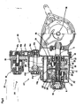
- FIG. 3 is a cross sectional view in development of the front wheel drive shaft 5, rear wheel drive shaft 6, transmission unit 10, and the surroundings of these components
- FIG. 4 is a view in section taken along the line A-A in FIG. 1.
- the front wheel drive shaft 5 and the rear wheel drive shaft 6 are arranged on approximately the same axis longitudinally of the vehicle and spaced apart from each other at their opposed ends. More specifically, a predetermined space is provided between the rear end face of the shaft 5 and the front end face of the shaft 6.
- a differential gear unit 65 for driving the front axle 75 is connected to the front end of the front wheel drive shaft 5, while the aforementioned rear wheel drive unit 70 is connected to the rear end of the rear wheel drive shaft 6.
- the transmission unit 10 comprises a main drive shaft 11 disposed in the space between the front wheel drive shaft 5 and the rear wheel drive shaft 6 on the same axis as these shafts, a front wheel planetary gear unit 20 interconnecting the main drive shaft 11 and the front wheel drive shaft 5, a rear wheel planetary gear unit 20' interconnecting the main drive shaft 11 and the rear wheel drive shaft 6, a driving power transmission mechanism 13 interconnecting the hydraulic motor shaft 56 of the main HST and the main drive shaft 11, and a casing 12 housing these components.
- the front wheel planetary gear unit 20 comprises a sun gear 21 mounted on the main drive shaft 11, an outer wheel 23 having an inner gear 22 surrounding the sun gear 21, a plurality of planetary gears 24 meshing with both the sun gear 21 and the inner gear 22, and a carrier 25 supported by the front wheel drive shaft 5 nonrotatably relative thereto.
- the carrier 25 is made to rotate with the revolution of the planetary gears 24 around the sun gear 21.
- a gear 27 is provided on the outer periphery of the outer wheel 23.
- the rear wheel planetary gear unit 20' also comprises the same components as the unit 20, i.e., a sun gear 21', an outer wheel 23', planetary gears 24', a carrier 25' and a gear 27'.
- the driving power transmission mechanism 13 is a power transmission gear mechanism which comprises a gear 13a mounted on the motor shaft 56 of the main HST 50 nonrotatably relative thereto, an intermediate gear 13b meshing with the gear 13a, an idle shaft 13c supporting the intermediate gear 13b thereon rotatably relative thereto, a gear 13d meshing with the intermediate gear 13b, a support shaft 13e supporting the gear 13d thereon nonrotatably relative thereto, a gear 13f mounted on the support shaft 13e nonrotatably relative thereto, and a gear 13g meshing with the gear 13f and supported on the main drive shaft 11 nonrotatably relative thereto, whereby an improved transmission efficiency is achieved.
- the transmission mechanism 13 can be of the belt type, it is then likely that the mechanism will be impaired in transmission efficiency, for example, owing to slippage of the belt, whereas such a drawback can be effectively precluded with the mechanism of the present embodiment.
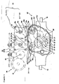
- FIG. 5 is a development in vertical section of the differential unit 30 and the vicinity thereof.
- the differential unit 30 comprises a differential HST 31 having a hydraulic pump 32 and a hydraulic motor 35 at least one of which is of the variable displacement type.
- the hydraulic pump 32 is of the variable displacement type
- the hydraulic motor 35 is a fixed displacement motor.
- the hydraulic pump 32 is disposed in front of the hydraulic block 85 and has a pump shaft provided by a forwardly projecting portion of the pump shaft 53 of the main HST 50. Indicated at 34 in FIG.
- the hydraulic motor 35 is disposed in parallel to the main HST 50, in the rear of the casing of the differential gear unit 65 as seen in FIGS. 1, 4 and 5.
- the differential unit 30 further comprises a differential power transmission mechanism 40 for delivering the rotational output of the hydraulic motor 35 of the differential HST 31 to the front wheel planetary gear unit 20 and the rear wheel planetary gear unit 20' therethrough.
- the power transmission mechanism 40 is adapted to give the outer wheel 23' of the rear wheel planetary gear unit 20' and the outer wheel 23 of the front wheel planetary gear unit 20 additional rotations in opposite directions to each other.
- the mechanism 40 comprises, as shown in FIGS.
- a gear 40a mounted on the motor shaft 36 of the differential HST 31 nonrotatably relative thereto, an intermediate gear 40b meshing with the gear 40a, an idle shaft 40c supporting the intermediate gear 40b thereon rotatably relative thereto, a gear 40d meshing with the intermediate gear 40b, a support shaft 40e supporting the gear 40d thereon nonrotatably relative thereto, and a gear 40f mounted on the support shaft 40e nonrotatably relative thereto.
- the mechanism 40 further comprises a front wheel transmission member 41 for delivering a rotation of the same direction as the rotation of the gear 40f to the outer wheel 23 of the front wheel planetary gear unit 20, and a rear wheel transmission member 41' for delivering a rotation opposite in direction to the rotation of the gear 40f to the outer wheel 23' of the rear wheel planetary gear unit 20'.
- the front wheel transmission member 41 comprises a gear member 41a meshing with both the gear 40f and the outer wheel 23 of the front wheel planetary gear unit 20.
- the rear wheel transmission member 41' comprises an idle gear 41b', an idle shaft 41c' supporting the idle gear 41b' thereon rotatably relative thereto, and a gear member 41a' meshing with both the idle gear 41b' and the outer wheel 23' of the rear wheel planetary gear unit 20'.
- the differential unit 30 is further provided with a link mechanism 45 for operatively connecting the movable swash plate 34 of the hydraulic pump 32 of the differential HST 31 to a steering wheel 90 at the driver's seat.
- FIG. 6 shows the steering wheel 90 and the rear wheels 8 as coupled thereto.
- Indicated at 46 in the drawing is a rack-and-pinion assembly.
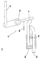
- FIGS. 7 to 9 schematically show the link mechanism 45.
- FIG. 7 shows the state of the link mechanism 45 when the vehicle is advanced straight.
- FIGS. 8 and 9 show the states of the link mechanism 45 when the vehicle is turned to the left and when the vehicle is turned to the right, respectively.
- the link mechanism 45 comprises the rack-and-pinion assembly 46, a pivotal plate 47 movable about a pivot 48a in operative relation with the assembly 46, and a connector 49 for connecting the pivotal plate 47 to the movable swash plate 34.
- the rack-and-pinion assembly 45 comprises a pinion 46a fixed to the rotary shaft of the steering wheel 90, and a pair of racks 46b, 46c arranged at opposite sides of the pinion 46a. In operative relation with the rotation of the steering wheel, one of the racks is slidable toward the pivotal plate, and the other rack is slidable in the opposite direction. As shown in FIG. 7, the pair of racks 46b, 46c are so adapted that the corresponding rack ends are in the same position when the vehicle is advanced straight, that is, when the steering wheel 90 is not rotated. The pair of racks 46b, 46c are arranged at different positions with respect to the direction of rotary shaft of the pinion 46a and are therefore unlikely to come into contact with each other.
- the pivotal plate 47 is biased toward the pair of racks 46b, 46o by a biasing member 48b at all times.
- the connector 49 is so connected to the swash plate 34 as not to incline the swash plate 34 when the vehicle is advanced straight, namely, when the pivotal plate 47 is in the position shown in FIG. 7 and as to incline the swash plate 34 when the vehicle is turned, namely when the pivotal plate is in the position shown in FIG. 8 or 9.
- the link mechanism 45 operates in the following manner.
- the pair of racks 46b, 46c do not push the pivotal plate 47.
- the pivotal plate 47 in this state does not incline the movable swash plate 34 as stated above. Accordingly, the motor shaft 36 of the differential HST 31 is held out of rotation during the straight advance of the vehicle. If the vehicle is turned leftward or rightward, i.e., when the steering wheel 90 is rotated counterclockwise or clockwise, one of the racks 46b, 46c pushes the pivotal plate 47 as shown in FIG. 8 or 9, whereby the pivotal plate 47 is moved about the pivot 48a to incline the swash plate 34.
- the motor shaft 36 of the differential HST 31 rotates when the vehicle is turned.
- the inclination of the swash plate 34 is in proportion to the angle through which the pivotal plate 47 is pivotally moved, and the angle of pivotal movement of the pivotal plate 47 is proportional to the rotation angle of the steering wheel 90, so that the rotational speed of the motor shaft 36 of the differential HST 31 varies in proportion to the rotation angle of the steering wheel 90, i.e., to the steering angle of the rear wheels 8. It is desired to incline the end portions of the racks 46b, 46c to be brought into contact with the pivotal plate 47 as shown in FIGS.
- FIG. 10 is a diagram of the power transmission system of the vehicle 100 comprising the driving apparatus 1.
- the transmission unit 10 for transmitting the rotational output of the main HST 50 will be described first.
- the rotational output of the motor shaft 56 of the main HST 50 is transmitted by the driving power transmission mechanism 13 to the main drive shaft 11, which has fitted therearound the sun gear 21 of the front wheel planetary gear unit 20 and the sun gear 21' of the rear wheel planetary gear unit 20'. Accordingly, the sun gears 21, 21' are rotated at the same speed in the same direction.
- the differential unit 30 will be described next.
- the differential unit 30 operates in the following manner.
- the motor shaft 36 of the differential HST 31 does not rotate as previously stated. Consequently, the outer wheels 23, 23' coupled to the motor shaft 36 by the differential power transmission mechanism 40 are held out of rotation.
- the inner gears 22, 22' of the planetary gear units 20, 20' are held fixed when the vehicle is advanced straight.
- the sun gears 24, 24' are held in rotation at the same speed in the same direction by the rotational output of the main HST 50 as previously stated.
- the planetary gears 24, 24' revolve at the same speed in the same direction, causing the pins 26, 26' to rotate the respective carriers 25, 25' at the same speed in the same direction.
- the front wheel drive shaft 5 and the rear wheel drive shaft 6 are rotated at the same speed in the same direction, rotating the front and rear wheels 7, 8 at the same speed in the same direction.
- the gear ratio between the sun gears 21, 21' and the carrier 25, 25' will be considered.
- the number of teeth of each of the sun gears 21, 21' is Za
- the number of teeth of each of the planetary gears 24, 24' is Zb
- the number of teeth of each of the inner gears 22, 22' is Zc.
- the carriers 25, 25' rotate Nd turns when the sun gears 21, 21' are rotated Na turns
- the number of turns Nc of the outer wheels 23, 23' is expressed by Equation (1) in Table 1.
- N d ( Z a ⁇ N a ) / ( Z a + Z c ) .
- the differential unit 30 when the vehicle is turned, namely, when the steering wheel 90 is rotated counterclockwise or clockwise.
- the motor shaft 36 of the differential HST 31 rotates at a speed in accordance with the rotation angle of the steering wheel 90 as already described.
- the rotational output of the motor shaft 36 of the differential HST 31 is delivered through the differential power transmission mechanism 40 to the outer wheel 23 of the front wheel planetary gear unit 20 and the outer wheel 23' of the rear wheel planetary gear unit 20' as additional rotations in directions opposite to each other.
- the carrier 25' of the gear unit 20' is rotated at an increased speed while the carrier 25 of the gear unit 20 is rotated at a decreased speed when the differential power transmission mechanism 40 is so designed as to rotate the outer wheel 23' of the gear unit 20' in the same direction as the rotation of the sun gear 21' and to rotate the outer wheel 23 of the gear unit 20 in opposite direction to the rotation of the sun gear 21. Consequently, the rear wheel drive shaft 6 rotates at a higher speed than when advancing the vehicle straight, and the front wheel drive shaft 5 rotates at a lower speed than when advancing the vehicle straight, causing the rear wheels 8 to rotate at an increased speed and the front wheels 7 to rotate at a reduced speed.
- the driving apparatus 1 is adapted to rotate the steerable wheels and the nonsteerable wheels at the same speed when advancing the vehicle straight and to rotate the steerable wheels, i.e., the rear wheels 8, at an increased speed and the nonsteerable wheels, i.e., the front wheels 7, at a reduced speed when turning the vehicle.
- the driving apparatus 1 is adapted to drive the steerable wheels at an increased speed and the nonsteerable wheels at a decreased speed and therefore provides a capability of a great rotational speed difference between the steerable wheels and the nonsteerable wheels. Accordingly, even if a great difference occurs in turning radius between the steerable wheel and the nonsteerable wheel by a sharp turn of the vehicle, a speed difference is readily available to offset the great difference in turning radius.
- the driving apparatus 1 is so designed as to vary the speed increasing ratio of the steerable wheels and the reduction ratio of the nonsteerable wheels by varying the speed of the motor shaft 36 of the differential HST in proportion to the rotation angle of the steering wheel 90. It is therefore possible to produce a rotational speed difference between the steerable wheel and the nonsteerable wheel in accordance with the turning radius difference therebetween which varies in proportion to the steering angle of the steering wheel.
- the conventional driving apparatus which gives a definite rotational speed to the nonsteerable wheels and gives the steerable wheels only two different rotational speeds, i.e., the same speed as the nonsteerable wheels and a speed higher than this speed
- the rotational speed difference between the steerable wheel and the nonsteerable wheel is constant regardless of the steering angle of the steering wheel, whereas the difference in turning radius between the steerable wheel and the nonsteerable wheel varies with the steering angle of the steering wheel.
- the conventional apparatus is therefore unable to effectively preclude the steerable wheel from skidding.
- the rotational speed difference between the steerable wheel and the nonsteerable wheel is variable with the steering angle of the steering wheel, so that the skid of the steerable wheel can be prevented effectively in accordance with the steering angle of the steering wheel.
- the present embodiment has been described with reference to a vehicle wherein the rear wheels are steerable wheels and the front wheels are nonsteerable wheels, the invention is not limited to such vehicles but is of course applicable also to vehicles wherein the front wheels serve for steering, and the rear wheels are nonsteerable wheels.
- FIG. 12 shows another embodiment of the driving apparatus of the present invention.
- the driving apparatus which has basically the same construction as the foregoing embodiment, comprises a transmission unit 10' for receiving the rotational output of the main HST 50, and a differential unit 30' for adjusting the rotation of the steerable wheel drive shaft 5 and the nonsteerable wheel drive shaft 6 according to the steering angle of the steering wheel.
- the steerable wheel drive shaft 5 and the nonsteerable wheel drive shaft 6 are arranged on approximately the same axis and spaced apart from each other at opposed ends thereof.
- the transmission unit 10' comprises a first differential gear mechanism 110 having a pair of first sun bevel gears 115, 116 fixedly mounted on the steerable wheel drive shaft 5 and the nonsteerable wheel drive shaft 6, respectively, at their opposed ends.
- the first differential gear mechanism 110 comprises a first casing 111 covering the pair of first sun gears 115, 116 and rotatably supported on the drive shafts 5, 6, a first ring gear 112 provided externally on the first casing 111 for receiving the rotational output from the main HST 50, and a plurality of first planetary bevel gears 114 meshing with the pair of first sun gears 115, 116 and rotatably supported by a shaft 113 fixedly provided inside the first casing 111 and extending diametrically of the casing.
- the differential unit 30' comprises a differential HST 31 for receiving power from the drive source and outputting a differential rotational drive force, a second differential gear mechanism 130 for receiving the rotational output from the differential HST, and an adjusting transmission mechanism for transmitting an output from the second differential gear mechanism to the steerable wheel drive shaft 5 and the nonsteerable wheel drive shaft 6.
- the second differential gear mechanism 130 comprises a pair of rotary shafts 137, 138 supported by the housing of the driving apparatus, arranged on approximately the same axis and spaced apart from each other at opposed ends thereof, a pair of second sun bevel gears 135, 136 fixedly mounted on the respective rotary shafts at their opposed ends, a second casing 131 covering the pair of second sun gears and rotatably supported on the pair of rotary shafts, a second ring gear 132 provided externally on the second casing for receiving the rotational output from the differential HST 31, and a plurality of second planetary bevel gears 134 meshing with the pair of second sun gears and rotatably supported by a shaft 133 fixedly provided inside the second casing 131 end extending diametrically of the second casing.
- the adjusting transmission mechanism comprises two gear trains 140, 150 each comprising a drive gear 142 (154) fixed to the rotary shafts 137 (138), and a driven gear 141 (151) fixed to the steerable wheel drive shaft 5 (the nonsteerable wheel drive shaft 6). At least one of the two gear trains has at least one intermediate gear so as to render the two driven gears 141, 151 rotatable in directions different from each other. With the present embodiment, the gear train 150 has one intermediate gear 153 mounted on a shaft 152. In the gear trains 140, 150, the gears 141, 142 are equal in diameter, and the gears 151, 154 are equal in diameter.
- the driving apparatus shown in FIG. 12 operates in the following manner.
- the output of motor shaft 56 of the main HST 50 is delivered via the driving power transmission mechanism 13 to the ring gear 112.
- the rotation of the ring gear 112 is transmitted to the steerable wheel drive shaft 5 and the nonsteerable wheel drive shaft 6 by way of the first casing 111, the planetary gears 113 and the pair of sun gears 115, 116.
- the shafts 5, 6 have their rotational speed altered by the action of the two gear trains 140, 150 of the adjusting transmission mechanism in the following manner.
- the motor shaft 36 of the differential HST 31 does not rotate as in the first embodiment. Accordingly, the ring gear 132 and the second casing 131 are held out of rotation which are coupled to the motor shaft 36 via the differential power transmission mechanism 40. As a result, the rotary shafts 137, 138 of the second differential gear mechanism 130 are rotated at the same speed by the sun gears 135, 136 and the planetary gears 134. The gears 141 and 151 are therefore rotated also at the same speed. Consequently, the drive shafts 5, 6 connected to the first differential gear mechanism 110 are also rotated at the same speed, thus driving the steerable wheels and the nonsteerable wheels at the same speed.
- the motor shaft 36 of the differential HST 31 rotates at a speed in accordance with the rotation angle of the steering wheel in the driver's seat as described in the first embodiment.
- the output of the motor shaft 36 rotates the ring gear 132 of the second differential gear mechanism 130 via the differential power transmission mechanism 40.
- the second casing 131 therefore rotates, consequently increasing or reducing the number of revolutions of the shafts 137, 138 by a quantity equal to the number of revolutions of the second casing.
- the increase or reduction in the number of revolutions of the shafts 137, 138 is transmitted in the following manner.
- the two gear trains 140, 150 are so adapted that the two driven gears 141, 151 rotate in directions different from each other as previously described. In diameter, moreover, the gears 141, 142 are equal, and the gears 151, 154 are equal. Accordingly, when the rotary shafts 137, 138 rotate at a speed increased by the same number of revolutions, one of the gears 141, 151 increases and the other gear reduces in speed by the same number of revolutions.
- the steerable wheel drive shaft 5 is therefore rotated at an increased speed and the nonsteerable wheel drive shaft 6 at a reduced speed for turning the vehicle.
- the function described above is available by making the first and second differential gear mechanisms 110, 130 identical in construction and attaching these mechanisms, as oriented in opposite directions, to the housing of the driving apparatus. This permits use of common components for these two mechanisms, consequently leading to a reduction in manufacturing cost.
Landscapes
- Engineering & Computer Science (AREA)
- Chemical & Material Sciences (AREA)
- Combustion & Propulsion (AREA)
- Transportation (AREA)
- Mechanical Engineering (AREA)
- Motor Power Transmission Devices (AREA)
- Arrangement And Driving Of Transmission Devices (AREA)
- Non-Deflectable Wheels, Steering Of Trailers, Or Other Steering (AREA)
Claims (7)
- Appareil de transmission pour véhicule pour transmettre de la puissance via une transmission (50) hydrostatique principale provenant d'une source motrice installée dans la carrosserie du véhicule vers une première paire de roues motrices (8) et une seconde paire de roues motrices (7), les paires de roues étant situées à l'avant et à l'arrière de la carrosserie du véhicule et au moins une paire des paires de roues motrices pouvant être braquée, l'appareil de transmission comprenant:un dispositif (10) de transmission pour recevoir une sortie en rotation en provenance de la transmission hydrostatique principale,un premier arbre (6) de transmission et un second arbre (5) de transmission pour recevoir une sortie en rotation en provenance du dispositif de transmission et transmettant la sortie en rotation respectivement vers un essieu pour actionner la première paire de roues et un essieu pour actionner la seconde paire de roues,caractérisé par:un dispositif (30) différentiel pour augmenter la vitesse de rotation de l'un parmi les premier et second arbres de transmission et diminuer la vitesse de rotation de l'autre parmi les premier et second arbres de transmission proportionnellement selon l'angle de braquage d'un volant devant être manipulé par un conducteur,le dispositif de transmission comprenant un arbre (11) de transmission principal situé entre les premier et second arbres de transmission, un mécanisme (13) de transmission de la puissance d'actionnement pour transmettre la sortie en rotation de la transmission hydrostatique principale vers l'arbre de transmission principal, et un premier dispositif (20') de pignons planétaires et un second dispositif (20) de pignons planétaires pour transmettre la rotation de l'arbre de transmission principal respectivement vers les premier et second arbres de transmission de manière à mettre en rotation selon une même direction les arbres de transmission aux roues, etle dispositif différentiel comprenant une transmission (31) hydrostatique à différentiel pour recevoir la puissance provenant d'une source motrice et produisant une force motrice de rotation ajustée proportionnellement selon l'angle de braquage du volant, et un mécanisme (40) différentiel de transmission de la puissance pour recevoir la sortie en rotation provenant de la transmission hydrostatique à différentiel et fournissant des rotations additionnelles mutuellement opposées respectivement au premier dispositif de pignons planétaires et au second dispositif de pignons planétaires pour induire une augmentation de la vitesse de rotation et une diminution de la vitesse de rotation des premier et second arbres de transmission.
- Appareil de transmission selon la revendication 1, l'appareil étant en outre adapté pour un véhicule dans lequel la première paire de roues peut être directice et la seconde paire de roues n'est pas directrice, dans lequel
le premier arbre (6) de transmission et le second arbre (5) de transmission sont respectivement un arbre de transmission aux roues directrices et un arbre de transmission aux roues non directrices, et
le premier dispositif (20') de pignons planétaires et le second dispositif (20) de pignons planétaires sont respectivement un dispositif de pignons planétaires pour roues directrices et un dispositif de pignons planétaires pour roues non directrices. - Appareil de transmission selon la revendication 2, dans lequel l'arbre (6) de transmission aux roues directrices et l'arbre (5) de transmission aux roues non directrices sont agencés approximativement sur un axe commun et écartés l'un de l'autre aux extrémités opposées de celui-ci,
l'arbre (11) de transmission principal est situé entre les extrémités opposées de l'arbre de transmission aux roues directrices et de l'arbre de transmission aux roues non directrices sur le même axe que les deux arbres,
le dispositif (20') de pignons planétaires pour roues directrices a un premier pignon planétaire monté sur l'arbre de transmission principal, une première roue extérieure entourant le premier pignon planétaire, une première couronne dentée intérieure prévue sur la périphérie intérieure de la première roue extérieure, des premiers pignons satellites agencés entre le premier pignon planétaire et la première couronne intérieure, et un premier porte-satellites monté sur l'arbre de transmission aux roues directrices en ne pouvant pas tourner par rapport à celui-ci et en pouvant tourner avec les rotations des premiers pignons satellites, et
le dispositif (20) de pignons planétaires pour roues non-directrices a un second pignon planétaire monté sur l'arbre de transmission principal, une seconde roue extérieure entourant le second pignon planétaire, une seconde couronne dentée intérieure prévue sur la périphérie intérieure de la seconde roue extérieure, des seconds pignons satellites agencés entre le second pignon planétaire et la seconde couronne intérieure, et un second porte-satellites monté sur l'arbre de transmission aux roues non-directrices en ne pouvant pas tourner par rapport à celui-ci et en pouvant tourner avec les rotations des seconds pignons satellites. - Appareil de transmission selon la revendication 3, dans lequel le mécanisme (40) différentiel de transmission de puissance reçoit la sortie en rotation provenant de la transmission (31) hydrostatique à différentiel et ajuste les vitesses de rotation de la première couronne extérieure et de la seconde couronne extérieure respectivement dans des directions opposées de l'une par rapport à l'autre,
la transmission hydrostatique à différentiel est adaptée pour ne pas émettre de force d'entraînement en rotation quand le véhicule avance en ligne droite et d'émettre la force d'entraînement en rotation pendant un certain nombre de tours en fonction de l'angle de braquage du volant quand le véhicule vire,
le mécanisme différentiel de transmission de puissance est adapté pour ajuster la vitesse de rotation de la première couronne extérieure dans la même direction que la direction de rotation du premier pignon planétaire mis en rotation par la transmission (50) hydrostatique principale et pour ajuster la vitesse de rotation de la seconde couronne extérieure dans la direction opposée à la direction de rotation du second pignon planétaire mis en rotation par la transmission hydrostatique principale. - Appareil de transmission selon la revendication 4, dans lequel la transmission (31) hydrostatique à différentiel comprend une pompe hydraulique et un moteur hydraulique, au moins l'un d'entre la pompe hydraulique et le moteur hydraulique étant à débit variable sous l'action d'un organe changeant le débit,
le dispositif (30) différentiel comprend un mécanisme de liaison reliant le volant devant être manoeuvré par un conducteur à l'organe changeant le débit,
le mécanisme de liaison est adapté pour réduire à peu près à zéro un taux débité par l'un parmi la pompe hydraulique et le moteur hydraulique qui comprend l'organe changeant le débit quand le volant est positionné pour faire avancer le véhicule en ligne droite et pour augmenter le taux débité au fur et à mesure que l'angle de braquage augmente quand le volant est positionné pour faire virer le véhicule. - Appareil de transmission selon l'une quelconque des revendications 3 à 5, dans lequel le mécanisme (13) de transmission de la puissance motrice et le mécanisme (40) différentiel de transmission de puissance sont chacun un mécanisme à pignons pour transmettre la puissance.
- Appareil de transmission pour véhicules afin de transmettre de la puissance provenant d'une source motrice installée dans la carrosserie du véhicule vers les roues directrices et vers les roues non-directrices via une transmission (50) hydrostatique principale, l'appareil de transmission comprenant:un dispositif (10') de transmission pour recevoir une sortie en rotation en provenance de la transmission hydrostatique principale,un arbre (6) de transmission des roues diectrices et un arbre (5) de transmission des roues non-directrices pour recevoir une sortie en rotation en provenance du dispositif de transmission et transmettant la sortie en rotation respectivement vers un essieu pour actionner les roues directrices et un essieu pour actionner les roues non-directrices,caractérisé par:un dispositif (30') de différentiel pour augmenter la vitesse de rotation de l'arbre de transmission aux roues directrices et diminuer la vitesse de rotation de l'arbre de transmission aux roues non-directrices proportionnellement selon l'angle de braquage du volant devant être manoeuvré par un conducteur,l'arbre de transmission aux roues diectrices et l'arbre de transmission aux roues non-directrices étant situés approximativement sur un axe commun et écartés l'un de l'autre aux extrémités opposées de celui-ci,le dispositif de transmission comprenant un premier mécanisme (110) différentiel à pignons ayant une paire de premiers pignons planétaires montés rigidement sur chacun d'entre l'arbre de transmission aux roues directrices et l'arbre de transmision aux roues non-directrices aux extrémités opposées de ceux-ci,le premier mécanisme différentiel à pignons comprenant un premier boîtier recouvrant la paire des premiers pignons planétaires et supporté en pouvant tourner sur les arbres de transmission, un premier pignon en couronne prévu sur l'extérieur du premier boîtier pour recevoir la sortie en rotation provenant de la transmission hydrostatique principale, et une pluralité de premiers pignons satellites venant en prise avec la paire des premiers pignons planétaires et supportés en pouvant tourner par un arbre prévu fixe à l'intérieur du premier boîtier et s'étendant diamétralement par rapport au boîtier,le dispositif de différentiel comprenant une transmission (31) hydrostatique à différentiel pour recevoir de la puissance provenant de la source motrice et transmettant une force motrice de rotation, un second mécanisme (130) différentiel à pignons pour recevoir la sortie en rotation provenant de la transmission hydrostatique à différentiel, et un mécanisme (140, 150) de transmission à ajustement pour transmettre une sortie provenant du second mécanisme différentiel à pignons vers l'arbre de transmission aux roues directrices et l'arbre de transmission aux roues non-directrices,le second mécanisme différentiel à pignons comprenant une paire d'arbres de rotation supportés dans un carter de l'appareil de transmission, agencés approximativement sur l'axe commun et écartés l'un de l'autre aux extrémités opposées de celui-ci, une paire de seconds pignons planétaires montés fixes sur les arbres de rotations respectifs à leurs extrémités opposées, un second boîtier recouvrant la paire des seconds pignons planétaires et supporté en pouvant tourner sur la paire d'arbres de rotation, un second pignon en couronne prévu sur l'extérieur du second boîtier pour recevoir la sortie en rotation provenant de la tranmission hydrostatique principale, et une pluralité de seconds pignons satellites venant en prise avec la paire des seconds pignons planétaires et supportés en pouvant tourner sur un arbre prévu fixe à l'intérieur du second boîtier et s'étendant diamétralement par rapport au second boîtier,le mécanisme de transmission à ajustement comprenant deux trains de pignons prévus respectivement pour l'arbre de transmission aux roues directrices et l'arbre de transmission aux roues non-directrices et comprenant chacun un pignon moteur fixé à l'arbre de rotation, et un pignon entraîné fixé à l'arbre de transmission correspondant, au moins un des deux trains de pignons ayant au moins un pignon intermédiaire de sorte que les deux pignons entraînés puissent être mis en rotation dans des directions différentes l'un par rapport à l'autre, le pignon moteur et le pignon entraîné de chacun des trains de pignons étant égaux en diamètre.
Applications Claiming Priority (2)
| Application Number | Priority Date | Filing Date | Title |
|---|---|---|---|
| JP10320756A JP2000142153A (ja) | 1998-11-11 | 1998-11-11 | 車輌の走行装置 |
| JP32075698 | 1998-11-11 |
Publications (3)
| Publication Number | Publication Date |
|---|---|
| EP1000793A2 EP1000793A2 (fr) | 2000-05-17 |
| EP1000793A3 EP1000793A3 (fr) | 2001-03-07 |
| EP1000793B1 true EP1000793B1 (fr) | 2006-10-18 |
Family
ID=18124927
Family Applications (1)
| Application Number | Title | Priority Date | Filing Date |
|---|---|---|---|
| EP99308952A Expired - Lifetime EP1000793B1 (fr) | 1998-11-11 | 1999-11-09 | Transmission pour véhicules |
Country Status (4)
| Country | Link |
|---|---|
| US (2) | US6382339B1 (fr) |
| EP (1) | EP1000793B1 (fr) |
| JP (1) | JP2000142153A (fr) |
| DE (1) | DE69933633D1 (fr) |
Cited By (3)
| Publication number | Priority date | Publication date | Assignee | Title |
|---|---|---|---|---|
| US8944191B2 (en) | 2008-03-26 | 2015-02-03 | Mtd Products Inc | Vehicle control systems and methods |
| US9254865B2 (en) | 2005-07-22 | 2016-02-09 | Mtd Products Inc | Steering systems, steering and speed coordination systems, and associated vehicles |
| US9365236B2 (en) | 2006-10-17 | 2016-06-14 | Mtd Products Inc | Vehicle control systems and methods |
Families Citing this family (27)
| Publication number | Priority date | Publication date | Assignee | Title |
|---|---|---|---|---|
| JP2000142153A (ja) * | 1998-11-11 | 2000-05-23 | Kanzaki Kokyukoki Mfg Co Ltd | 車輌の走行装置 |
| US6962219B2 (en) | 2001-09-17 | 2005-11-08 | Mtd Products Inc | Mechanical ZTR system with steering wheel |
| US6732828B1 (en) * | 2002-10-22 | 2004-05-11 | Robert Abend | Hydraulically driven vehicle |
| JP4131816B2 (ja) * | 2002-12-27 | 2008-08-13 | 株式会社 神崎高級工機製作所 | 走行車の駆動装置 |
| US6953327B1 (en) | 2003-03-11 | 2005-10-11 | Hydro-Gear Limited Partnership | Dual pump |
| US6971233B1 (en) | 2003-05-12 | 2005-12-06 | Hydro-Gear Limited Partnership | Pump apparatus |
| US7204779B2 (en) * | 2003-09-26 | 2007-04-17 | Koji Irikura | Hydraulic steering transaxle and hydraulic driving vehicle |
| US6973783B1 (en) | 2004-02-27 | 2005-12-13 | Hydro-Gear Limited Partnership | Zero turn drive apparatus |
| US7137250B1 (en) | 2004-03-08 | 2006-11-21 | Hydro-Gear Limited Partnership | Zero turn drive apparatus with power take off |
| JP4554252B2 (ja) * | 2004-03-31 | 2010-09-29 | 本田技研工業株式会社 | 4輪駆動車両の制御方法 |
| US7377105B1 (en) | 2004-11-12 | 2008-05-27 | Hydro-Gear Limited Partnership | Dual pump assembly |
| US7347047B1 (en) | 2004-11-12 | 2008-03-25 | Hydro-Gear Limited Partnership | Pump assembly |
| US7162870B1 (en) | 2004-11-12 | 2007-01-16 | Hydro-Gear Limited Partnership | Pump assembly |
| US7231999B2 (en) * | 2004-11-23 | 2007-06-19 | Deere & Company | Steerable primary axle |
| US7290633B2 (en) * | 2005-05-19 | 2007-11-06 | Deere & Company | Steering responsive wheel drive system |
| GB0517200D0 (en) | 2005-08-22 | 2005-09-28 | Torotrak Dev Ltd | Driving and steering of motor vehicles |
| GB0517201D0 (en) | 2005-08-22 | 2005-09-28 | Torotrak Dev Ltd | Driving and steering of motor vehicles |
| JP2007106138A (ja) * | 2005-09-13 | 2007-04-26 | Kanzaki Kokyukoki Mfg Co Ltd | 作業車両の動力伝達機構 |
| US9010105B1 (en) | 2007-08-01 | 2015-04-21 | Hydro-Gear Limited Partnership | Transmission and engine configuration |
| US9194473B1 (en) | 2009-06-26 | 2015-11-24 | Hydro-Gear Limited Partnership | Modular power distribution and drive system |
| US8393236B1 (en) * | 2009-06-26 | 2013-03-12 | Hydro-Gear Limited Partnership | Modular power distribution and drive system |
| CA2849723C (fr) | 2011-09-22 | 2019-11-05 | Mtd Products Inc | Systemes et procedes de commande de vehicule et vehicules associes |
| US11247556B2 (en) | 2015-12-17 | 2022-02-15 | Allison Transmission, Inc. | Axle assembly for a vehicle |
| CN109153323B (zh) | 2016-05-06 | 2021-09-10 | 艾里逊变速箱公司 | 具有电动机的车桥总成 |
| USD821930S1 (en) | 2016-06-06 | 2018-07-03 | Axletech International Ip Holdings, Llc | Gearbox assembly for an axle |
| CN107264627B (zh) * | 2017-06-29 | 2019-04-23 | 南京航空航天大学 | 一种agv原地快速转向装置 |
| USD927578S1 (en) | 2018-09-27 | 2021-08-10 | Allison Transmission, Inc. | Axle assembly |
Family Cites Families (16)
| Publication number | Priority date | Publication date | Assignee | Title |
|---|---|---|---|---|
| US3978937A (en) * | 1974-09-23 | 1976-09-07 | Clark Equipment Company | Hydrostatic propulsion system |
| US4399886A (en) * | 1980-12-09 | 1983-08-23 | Sundstrand Corporation | Controls for variable displacement motor and motors |
| DE3216821A1 (de) * | 1982-05-05 | 1983-11-10 | Zahnradfabrik Friedrichshafen Ag, 7990 Friedrichshafen | Hydrostatischer antrieb fuer fahrzeuge |
| JPS59176121A (ja) | 1983-03-24 | 1984-10-05 | Kubota Ltd | 四輪駆動車輛の前輪駆動制御装置 |
| CA1294559C (fr) | 1987-04-15 | 1992-01-21 | Terutaka Takei | Vehicule de travail |
| US4886142A (en) * | 1987-06-26 | 1989-12-12 | Kanzaki Kokyukoki Mfg. Co. Ltd. | Hydraulic four-wheel drive system |
| JPH0761779B2 (ja) * | 1988-03-14 | 1995-07-05 | 本田技研工業株式会社 | 車両の前後輪駆動装置 |
| US5207060A (en) * | 1991-09-03 | 1993-05-04 | Sauer, Inc. | Tandem hydraulic motor |
| US5335746A (en) * | 1993-01-19 | 1994-08-09 | Sauer Inc. | Electromagnetic clutch driven steerable axle |
| JP3445339B2 (ja) * | 1993-11-25 | 2003-09-08 | 株式会社 神崎高級工機製作所 | 作業車用四輪駆動トランスミッション |
| JP3824665B2 (ja) * | 1994-07-25 | 2006-09-20 | 株式会社 神崎高級工機製作所 | 作業車用トランスミッション |
| CA2132684A1 (fr) * | 1994-09-22 | 1996-03-23 | David L. Hoar | Vehicule utilitaire |
| DE29508396U1 (de) * | 1995-05-19 | 1995-08-10 | Joseph Vögele AG, 68163 Mannheim | Straßenfertiger |
| JP3160751B2 (ja) * | 1995-07-20 | 2001-04-25 | 本田技研工業株式会社 | 無段変速駆動車両における操舵制御装置 |
| GB9705056D0 (en) * | 1997-03-12 | 1997-04-30 | Massey Ferguson Ltd | Vehicle front wheel speed change apparatus |
| JP2000142153A (ja) * | 1998-11-11 | 2000-05-23 | Kanzaki Kokyukoki Mfg Co Ltd | 車輌の走行装置 |
-
1998
- 1998-11-11 JP JP10320756A patent/JP2000142153A/ja active Pending
-
1999
- 1999-11-09 DE DE69933633T patent/DE69933633D1/de not_active Expired - Fee Related
- 1999-11-09 EP EP99308952A patent/EP1000793B1/fr not_active Expired - Lifetime
- 1999-11-12 US US09/439,248 patent/US6382339B1/en not_active Expired - Fee Related
-
2002
- 2002-03-04 US US10/090,351 patent/US6637535B2/en not_active Expired - Fee Related
Cited By (4)
| Publication number | Priority date | Publication date | Assignee | Title |
|---|---|---|---|---|
| US9254865B2 (en) | 2005-07-22 | 2016-02-09 | Mtd Products Inc | Steering systems, steering and speed coordination systems, and associated vehicles |
| US9409596B2 (en) | 2005-07-22 | 2016-08-09 | Mtd Products Inc | Steering systems, steering and speed coordination systems, and associated vehicles |
| US9365236B2 (en) | 2006-10-17 | 2016-06-14 | Mtd Products Inc | Vehicle control systems and methods |
| US8944191B2 (en) | 2008-03-26 | 2015-02-03 | Mtd Products Inc | Vehicle control systems and methods |
Also Published As
| Publication number | Publication date |
|---|---|
| JP2000142153A (ja) | 2000-05-23 |
| EP1000793A2 (fr) | 2000-05-17 |
| DE69933633D1 (de) | 2006-11-30 |
| EP1000793A3 (fr) | 2001-03-07 |
| US6382339B1 (en) | 2002-05-07 |
| US6637535B2 (en) | 2003-10-28 |
| US20020112910A1 (en) | 2002-08-22 |
Similar Documents
| Publication | Publication Date | Title |
|---|---|---|
| US6382339B1 (en) | Driving apparatus for vehicles | |
| US7493975B2 (en) | Multi-wheel vehicle | |
| US20200377151A1 (en) | Vehicle Control Systems and Methods | |
| US7059433B2 (en) | Riding lawn mower | |
| US7204779B2 (en) | Hydraulic steering transaxle and hydraulic driving vehicle | |
| US6336513B1 (en) | Multi-axle vehicle with two hydrostatic transmissions for driving-steering | |
| EP0743219B1 (fr) | Finisseur | |
| US6554085B2 (en) | Multi-wheel vehicle with transmission for driving-steering | |
| US2595494A (en) | Four-wheel drive tractor | |
| WO2000019127A1 (fr) | Transmission pour variation de vitesse et direction d'un vehicule | |
| EP1155898A4 (fr) | Deplacement par commande d'un vehicule et dispositif de commande par essieux hydromecaniques integres pour direction | |
| EP1100711B1 (fr) | Appareil d'entrainement pour changer les vitesses et diriger un vehicule | |
| GB2299794A (en) | Articulated machine with powered differential steering | |
| EP1386824B1 (fr) | Système de direction pour véhicule à quatre roues motrices | |
| JP3084479B2 (ja) | 移動農機 | |
| JP2001224204A (ja) | 走行装置 |
Legal Events
| Date | Code | Title | Description |
|---|---|---|---|
| PUAI | Public reference made under article 153(3) epc to a published international application that has entered the european phase |
Free format text: ORIGINAL CODE: 0009012 |
|
| AK | Designated contracting states |
Kind code of ref document: A2 Designated state(s): DE GB |
|
| AX | Request for extension of the european patent |
Free format text: AL;LT;LV;MK;RO;SI |
|
| PUAL | Search report despatched |
Free format text: ORIGINAL CODE: 0009013 |
|
| AK | Designated contracting states |
Kind code of ref document: A3 Designated state(s): AT BE CH CY DE DK ES FI FR GB GR IE IT LI LU MC NL PT SE |
|
| AX | Request for extension of the european patent |
Free format text: AL;LT;LV;MK;RO;SI |
|
| 17P | Request for examination filed |
Effective date: 20010813 |
|
| AKX | Designation fees paid |
Free format text: DE GB |
|
| 17Q | First examination report despatched |
Effective date: 20020322 |
|
| GRAP | Despatch of communication of intention to grant a patent |
Free format text: ORIGINAL CODE: EPIDOSNIGR1 |
|
| GRAS | Grant fee paid |
Free format text: ORIGINAL CODE: EPIDOSNIGR3 |
|
| GRAA | (expected) grant |
Free format text: ORIGINAL CODE: 0009210 |
|
| AK | Designated contracting states |
Kind code of ref document: B1 Designated state(s): DE GB |
|
| REG | Reference to a national code |
Ref country code: GB Ref legal event code: FG4D |
|
| REF | Corresponds to: |
Ref document number: 69933633 Country of ref document: DE Date of ref document: 20061130 Kind code of ref document: P |
|
| PG25 | Lapsed in a contracting state [announced via postgrant information from national office to epo] |
Ref country code: DE Free format text: LAPSE BECAUSE OF NON-PAYMENT OF DUE FEES Effective date: 20070601 |
|
| PLBE | No opposition filed within time limit |
Free format text: ORIGINAL CODE: 0009261 |
|
| STAA | Information on the status of an ep patent application or granted ep patent |
Free format text: STATUS: NO OPPOSITION FILED WITHIN TIME LIMIT |
|
| GBPC | Gb: european patent ceased through non-payment of renewal fee |
Effective date: 20070118 |
|
| 26N | No opposition filed |
Effective date: 20070719 |
|
| PG25 | Lapsed in a contracting state [announced via postgrant information from national office to epo] |
Ref country code: GB Free format text: LAPSE BECAUSE OF NON-PAYMENT OF DUE FEES Effective date: 20070118 |