EP1000802A1 - Système de hayon élévateur - Google Patents
Système de hayon élévateur Download PDFInfo
- Publication number
- EP1000802A1 EP1000802A1 EP00101237A EP00101237A EP1000802A1 EP 1000802 A1 EP1000802 A1 EP 1000802A1 EP 00101237 A EP00101237 A EP 00101237A EP 00101237 A EP00101237 A EP 00101237A EP 1000802 A1 EP1000802 A1 EP 1000802A1
- Authority
- EP
- European Patent Office
- Prior art keywords
- tail lift
- vehicle
- cylinder device
- lifting
- essentially
- Prior art date
- Legal status (The legal status is an assumption and is not a legal conclusion. Google has not performed a legal analysis and makes no representation as to the accuracy of the status listed.)
- Granted
Links
- 238000003860 storage Methods 0.000 claims abstract description 4
- 238000007688 edging Methods 0.000 claims 1
- 238000010276 construction Methods 0.000 description 8
- 238000000034 method Methods 0.000 description 4
- 238000005452 bending Methods 0.000 description 3
- 238000004519 manufacturing process Methods 0.000 description 3
- 239000011265 semifinished product Substances 0.000 description 3
- 238000003466 welding Methods 0.000 description 3
- 238000005520 cutting process Methods 0.000 description 2
- 238000010586 diagram Methods 0.000 description 2
- 239000000463 material Substances 0.000 description 2
- 238000004080 punching Methods 0.000 description 2
- 229910001208 Crucible steel Inorganic materials 0.000 description 1
- 229910000831 Steel Inorganic materials 0.000 description 1
- 230000002411 adverse Effects 0.000 description 1
- 239000002131 composite material Substances 0.000 description 1
- 230000010354 integration Effects 0.000 description 1
- 238000012423 maintenance Methods 0.000 description 1
- 238000004091 panning Methods 0.000 description 1
- 238000003825 pressing Methods 0.000 description 1
- 239000010959 steel Substances 0.000 description 1
Images


Classifications
-
- B—PERFORMING OPERATIONS; TRANSPORTING
- B60—VEHICLES IN GENERAL
- B60P—VEHICLES ADAPTED FOR LOAD TRANSPORTATION OR TO TRANSPORT, TO CARRY, OR TO COMPRISE SPECIAL LOADS OR OBJECTS
- B60P1/00—Vehicles predominantly for transporting loads and modified to facilitate loading, consolidating the load, or unloading
- B60P1/44—Vehicles predominantly for transporting loads and modified to facilitate loading, consolidating the load, or unloading having a loading platform thereon raising the load to the level of the load-transporting element
- B60P1/4414—Vehicles predominantly for transporting loads and modified to facilitate loading, consolidating the load, or unloading having a loading platform thereon raising the load to the level of the load-transporting element and keeping the loading platform parallel to the ground when raising the load
-
- B—PERFORMING OPERATIONS; TRANSPORTING
- B60—VEHICLES IN GENERAL
- B60P—VEHICLES ADAPTED FOR LOAD TRANSPORTATION OR TO TRANSPORT, TO CARRY, OR TO COMPRISE SPECIAL LOADS OR OBJECTS
- B60P1/00—Vehicles predominantly for transporting loads and modified to facilitate loading, consolidating the load, or unloading
- B60P1/44—Vehicles predominantly for transporting loads and modified to facilitate loading, consolidating the load, or unloading having a loading platform thereon raising the load to the level of the load-transporting element
- B60P1/4471—General means for controlling movements of the loading platform, e.g. hydraulic systems
-
- B—PERFORMING OPERATIONS; TRANSPORTING
- B60—VEHICLES IN GENERAL
- B60P—VEHICLES ADAPTED FOR LOAD TRANSPORTATION OR TO TRANSPORT, TO CARRY, OR TO COMPRISE SPECIAL LOADS OR OBJECTS
- B60P1/00—Vehicles predominantly for transporting loads and modified to facilitate loading, consolidating the load, or unloading
- B60P1/44—Vehicles predominantly for transporting loads and modified to facilitate loading, consolidating the load, or unloading having a loading platform thereon raising the load to the level of the load-transporting element
- B60P1/4485—Attaching the complete loading platform unit to the vehicle
-
- Y—GENERAL TAGGING OF NEW TECHNOLOGICAL DEVELOPMENTS; GENERAL TAGGING OF CROSS-SECTIONAL TECHNOLOGIES SPANNING OVER SEVERAL SECTIONS OF THE IPC; TECHNICAL SUBJECTS COVERED BY FORMER USPC CROSS-REFERENCE ART COLLECTIONS [XRACs] AND DIGESTS
- Y10—TECHNICAL SUBJECTS COVERED BY FORMER USPC
- Y10S—TECHNICAL SUBJECTS COVERED BY FORMER USPC CROSS-REFERENCE ART COLLECTIONS [XRACs] AND DIGESTS
- Y10S414/00—Material or article handling
- Y10S414/13—Handlers utilizing parallel links
Definitions
- the invention relates to a tail lift system for Attachment to vehicles, especially trucks, each comprising an essentially parallelogram-shaped two essentially parallel spaced-apart structures existing lifting and Folding structure, an essentially plate-shaped Loading platform for lifting and lowering a load and for Locking a storage space of the vehicle and one Lift cylinder device for lifting and lowering the tail lift and a folding cylinder device for pivoting the tail lift from the horizontal to the Vertical and vice versa.
- Tail lift systems of this type have been known for a long time and are used in particular in trucks, to be transported by truck Loads on site from the loading platform of the truck on the lane on which the truck stands to be able to lower, so that the load then brought to the destination elsewhere can.
- Tail lift systems of the known known above Art thus have two cylinder devices, wherein regularly the lifting cylinder device with a supporting structure of the parallelogram-shaped lifting and folding structure interacts, whereas the folding cylinder device with the other structure of the lifting and folding structure cooperates.
- tail lift systems known in the prior art of the type described above occur during loading and unloading, i.e. under the influence of a force that is in Dependence of the goods to be lifted or lowered significant sizes
- problems in that due to the on the tail lift itself bending load of the tail lift occur relative to the loading area of the truck can, so that gap between the tail lift and the Level of the loading area both in the horizontal direction and also arise in the vertical direction, which, based on the width of the loading area opening is also considerable can vary.
- the result is that in particular heavy loads with the tail lift in vertical Direction, i.e. during loading and unloading must be real thresholds between levels the tail lift and the loading area of the truck arise so that the load often over this Threshold, be it with handcarts, by hand or by means of other auxiliary device, are balanced got to.
- the real reason for the appearance of the horizontal and vertical column, which is also on one side the width of the loading area has to be increased due to the design its cause is that the lifting cylinder device and the folding cylinder device on the side offset the lifting and folding structure to the two individual structural structures, i.e. across to Opening of the loading area or transversely to the tail lift are arranged so that due to this construction considerable leverage can occur under load, which the creation of the horizontal and vertical column under load.
- the object is achieved according to the invention in that the force introduction points of the lifting cylinder device and the folding cylinder device into the lifting and folding supporting structure in each case in the plane of the pivot points A 1 , C 1 , D, E 1 ; A 2 , B, C 2 , E 2 of the elements of the respective first and second supporting structure lie in which the lifting cylinder device (first supporting structure) and the folding cylinder device (second supporting structure) are in relation to those which you have exerted on the supporting structure or in the supporting structure Act forces.
- the advantage of the solution proposed according to the invention consists essentially in that due to the arrangement the essentially parallelogram structures, the two together the lifting and folding structure form, and the arrangement of the lifting cylinder device and the folding cylinder device in each case in the Rotation level of the respective structure, i.e. so not in Transverse direction offset to each other, no torques in Transverse direction can occur so that it is guaranteed that there are no vertical and horizontal gaps Direction between the tail lift at horizontal Alignment relative to the loading level of a vehicle can train and also not opening column at vertical alignment of the tail lift in the cargo hold condition of a vehicle.
- tail lift system Another significant advantage of the tail lift system according to the invention is also that this is simple can be designed constructively and because of chosen construction also no uneven load is exerted on the lifting and folding structure, so that this remains stable over long periods of time and thus maintenance work to a minimum is reduced.
- the first structure comprises two essentially parallel first spaced structures, wherein the first support arms about a first axis of rotation are rotatably attached to the vehicle and via a second arranged at the opposite end of the first support arms second axis of rotation with a first end of the lifting cylinder device are attached and being the second End of the lifting cylinder device via an axis of rotation is rotatably attached to the vehicle.
- the first structure comprises one second support arm, which at its first end with both first support arms is connected, the second end one essentially orthogonal to the first two Carrying arms extending axis of rotation over which the second support arm rotatably attached to the tail lift is.
- Support arm can be designed in any suitable manner can, the advantageous proposed according to the invention
- the solution ensures simple, constructive solutions Way that the condition is easily met can be that the fulcrums of the elements of the first Structure, in which also the lifting cylinder device is arranged, lie in one plane.
- the second support arm essentially in the middle plane between the first two Support arms is arranged, making it a very simple and inexpensive training and integration of the second Support arm is reachable in the first structure.
- the tail lift system includes the second Structure two essentially parallel to each other spaced apart first support arms, the first support arms attached rotatably to the vehicle via a first axis of rotation and a second, at the other end of the first Support arms arranged second axis of rotation, which essentially orthogonal to the first arms and parallel runs to the first axis, rotatable with the tail lift are attached.
- the second The structure is also structurally very simple can be to meet the condition that the pivot points of the elements of the second structure, in the too the folding cylinder device as part of the parallelogram of the second structure is arranged in a Rotation level can lie, although in principle also other constructions are conceivable, which the above Basic condition of the proposed according to the invention Solution.
- the proposed solution is basically simpler constructive design very stable and therefore relatively inexpensive to manufacture.
- the folding cylinder device is rotatably attached to the vehicle at its first end, with its second end essentially around an axis of rotation orthogonal to the longitudinal axis of the folding cylinder device is rotatably attached to the tail lift, the Longitudinal axis essentially in the swivel plane forming plane of the second structure.
- the second structure is very constructive simply to meet the condition that the pivot points the elements of the second structure, the part of which also Folding cylinder device is formed, is fulfilled can be, although in principle also here constructive solutions are possible that are the basic condition fulfill.
- support arms can be chosen in any suitable manner, i.e. these support arms can be formed as molded parts, for example Cast steel or the like can be made, it has turned out to be very advantageous, however To form support arms essentially plate-shaped, so that these from plate-shaped semi-finished products, for example from steel plates or any other suitable plate-shaped materials, by cutting or punching out on simple and thus can be produced inexpensively.
- the tail lift system according to the invention can basically in any suitable manner on a supporting structure be attached to a vehicle usually tailgate systems of this type are attached become.
- the structures of a vehicle regularly by two arranged in parallel in the longitudinal direction of the vehicle spaced U-shaped beams formed which also the drive axis or axes of the Pick up the vehicle.
- the attachment is advantageously carried out of the first and second structure of the tail lift on Vehicle via a separate fastening element, the fastener itself being part of the is parallelogram-shaped respective structure, so that no separate structural elements are provided for this either must be and a via the fastener simple and quick attachment to the structure possible is.
- the fastener itself can be any have a suitable structural structure, it has turned out to be advantageous, however to form a plate, which in turn is a simple one Producibility, for example by punching or Cutting from plate-shaped semi-finished products or material plates, has the consequence.
- the fastener runs along one in the Vehicle mounted condition essentially vertical running crease or edge line with a first part towards the support frame of the vehicle and is with a second part to which the structure is attached is aligned essentially parallel to the supporting frame, with an obtuse angle ⁇ between the two parts is formed.
- the fastener is preferably with the support arms of a vehicle via a separate connecting element firmly connectable, that directly to the constructive Construction of the supporting frame of the respective vehicle, on which the tail lift system according to the invention to be assembled, can be adjusted. This is it is possible the entire remaining construction of the tail lift system train uniformly, so that if necessary only these fasteners on the different Structure of the support frame of the vehicle on which the tail lift system is to be fitted, adapted to will need.
- the connecting element preferably has a plate-shaped Structure and can in turn be stamped on simple way from plate-shaped semi-finished products or plate-shaped tools par excellence become.
- the fastener in the area of its crease or edge line at least connected to the free end of the leg is.
- the fastening element with the support frame of a vehicle over the above-described fixed connection by means of the connecting elements be attached, for example via Bolted connections and / or a welded connection.
- screw connections and weld connections one very precise adjustment and a very precise fixation of the Attachment points before the actual attachment process require and often an execution of Fastening holes in the support frame of the vehicle Strength is undesirable, which is equally for the execution of welded connections on the supporting frame applies, it is proposed that the tail lift system be such train that preferably the fasteners with the support frame of a vehicle over claw-like designed clamping elements over horizontal webs grab the support frame of the vehicle, releasably attachable are.
- the tail lift system 10 includes essentially a lifting and folding structure 12, which in turn from a first structure 13 and a second structure 14, which is substantially parallel to each other spaced on a vehicle 11 via fasteners 20, 21 are attached, being on the attachment will be discussed in more detail below.
- the first and the second supporting structure 13, 14 form together with the fastening elements 20, 21, the second supporting structure 14 additionally together with a folding cylinder device 17 shows a parallelogram-shaped structure as shown in FIG 5 can be seen, but what in individual will also be discussed below.
- first and second structure 13, 14 is in essential plate-shaped tail lift 15 for lifting and lowering a load (shown without load) and for Closing a storage space of the vehicle 11 rotatably connected.
- a lifting cylinder device acts with the first supporting structure 13 16 for lifting and lowering the tail lift 15 together.
- the first supporting structure 13, on the left in FIGS. 1 and 5 shown comprises two substantially parallel spaced-apart structures 130, 131, which over a first axis of rotation 132 on the fastening element 20 are rotatably attached.
- the one on the opposite end of the first support arms 130, 131 formed second axis of rotation 133 is with the first end 160 of the lifting cylinder device 16 attached, see also Fig. 6.
- Das second end 161 of the lifting cylinder device 16 also rotatably attached to the fastener 20.
- a second support arm 134 Essentially in the middle plane 138 between the first support arms 130, 131 is a second support arm 134 provided, see also Fig. 6.
- the second bracket 134 has its first end 135 with the first two Support arms 130, 131 attached such that a truss-like Bridging both first support arms 130, 131 is reached.
- the second end 136 of the second Support arm 134 is substantially orthogonal extending to the first two support arms 130, 131
- Axis of rotation 137 is rotatably attached to the tail lift 15.
- the most provided at the other end of the first support arms 140, 141 second axis of rotation 143 is substantially orthogonal to the first support arms 140, 141 and runs essentially parallel to the first axis of rotation 142 the axis of rotation 143 are the two first support arms 140, 141 rotatably attached to the tail lift 15.
- the folding cylinder device 17 provided, see also FIG. 5, the at its first end 170 rotatable about an axis of rotation 174 is fastened to the fastening element 21.
- an axis of rotation 172 which is substantially orthogonal to Longitudinal axis 173 of the folding cylinder device 17 is formed is rotatably attached to the tail lift 15.
- the (imaginary) longitudinal axis 173 runs essentially in the plane 19 of the second plane forming the swivel plane Structure 14, compare the chain-dotted line in Fig. 5.
- FIG. 5 in which the lever diagram of the parallelogram-shaped lifting and folding structure 12, ie the first structure 13 and the second structure 14, in connection with the lifting cylinder device 16 acting thereon and the folding cylinder device 17 integrally belonging to the second structure is shown.
- the force introduction points of the lifting cylinder device 16 and the folding cylinder device 17 into the lifting and folding supporting structure 12 lie in the respective plane 18 of the pivot points A 1 , C, C 1 , D, E 1 of the axes of rotation 137, 132, 133, 162 of the first supporting structure 13 and in plane 19 the pivot point A 2 , B, C 2 , E 2 of the axes 143, 172, 142, 174 of the second supporting structure 14.
- Part of the parallelogram structure 13, 14 are the respective fastening elements 20, 21, compare in particular Figures 2, 3 and 4 as well Fig. 5.
- This here also supporting structure 13, 14 Fasteners 20, 21 can flat sheet-like elements are formed in which axle bushings for the rotary axes 132, 162, 142, 174 can be easily recorded.
- the Fastening the fasteners 20, 21 on the support frame 110, 111 can, as shown in Figures 2 and 3 is done via screw connections, whereby but then the support frame 110, 111 of the vehicle 11 with corresponding through openings for receiving the here Drilled nut connections, not shown must become.
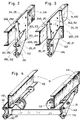
- the two mounting variants shown in Figures 2 and 3 of the fastener 20, 21 have to the vehicle 11 or the wedding frame 110, 111 grown condition a substantially vertical, i.e. orthogonal to the support frame 110, 111 Kink line 200, 210 on.
- the so educated first part 201, 211 of the fastening element 20, 21 thus runs in the direction of the support frame 110, 111 of the vehicle 11, whereas the second part 202, 212 of the fastening element 20, 21 on which the supporting structure 13, 14 is attached, substantially parallel to the support frame 110, 111 is aligned.
- an obtuse angle ⁇ educated is between the both parts 201, 211; 202, 212 an obtuse angle ⁇ educated.
- the support frame 110, 111 of the vehicle 10 is a in cross section L-shaped connecting element 24, 25 provided, the connecting element 24, 25 is attached to the support frame 110, 111 such that the first legs 240, 250 formed there transversely from Support frame 110, 111 stands out.
- the fastener 201, 211 is in the area of its crease or fold line 200, 210 with the free end 241, 251 of the leg 240, 250 connected, for example by means of one not here separately shown weld or a screw connection, the free end 203, 213 of the first part 201, 211 of the fastening element 20, 21 on plate-shaped base part of the connecting element 24, 25 by welding or another suitable connection is attached.
- the embodiment of the immediate one shown in FIG Fastening area of the tail lift system 10 the support frame 110, 111 of the vehicle 10 is similar constructed like the embodiment shown in FIG. 2, the connecting element 24, 25 shown in FIG. 3 however, also has a substantially transverse to Base of the connecting element 24, 25 and thus in installed condition transversely to the support frame 110, 111 aligned second leg 242, 252.
- the Fastening element 20, 21 is here opposite 2 with the free end 203, 213, its first part 201, 211 angled and over this angled leg with the second Legs 242, 252 of the connecting element 24, 25 connected.
- An angular profile 26 between the second part 202, 212 of the fastener 20, 21 and the first leg 240, 250 of the connecting element 24, 25 can also be provided, the angle profile 26 for example firmly welded to the fastener 20, 21 or can be screwed, the free Leg of the angle profile 26 and the angled free end 203, 213 of the first part 201, 211 of the Fastening element 20, 21 with through holes can be provided with appropriately adapted Through holes of the two legs 240, 250; 242, 252 of the connecting element 24, 25 depending on the Distance between the two support frames 110, 111 adapted and screwed and / or welded if necessary can, so that this variable design option at different distances from each other Support frame 110, 111 an easy adjustment is possible and also manufacturing tolerances in a simple manner without Difficulties can be bridged.
- FIGS. 1 and 4 An even more elegant solution is shown in FIGS. 1 and 4 shown, in which the fasteners 20, 21 with the support frame 110, 111 of the vehicle 11 via claw-like configured clamping elements 22, 23 are attached.
- the claw-like clamping elements 22, 23 reach regularly over horizontal webs 112, 113 U-shaped support frame of the vehicle, both in the essentially form the supporting frame, and can by means here screw terminal connections not shown separately be releasably attached.
Landscapes
- Engineering & Computer Science (AREA)
- Transportation (AREA)
- Mechanical Engineering (AREA)
- Vehicle Step Arrangements And Article Storage (AREA)
- Forklifts And Lifting Vehicles (AREA)
- Vehicle Body Suspensions (AREA)
- Control Of Driving Devices And Active Controlling Of Vehicle (AREA)
- Body Structure For Vehicles (AREA)
- Fluid-Pressure Circuits (AREA)
- Earth Drilling (AREA)
Priority Applications (1)
| Application Number | Priority Date | Filing Date | Title |
|---|---|---|---|
| DE59610634T DE59610634D1 (de) | 1996-05-21 | 1996-05-21 | Ladebordwandsystem |
Applications Claiming Priority (1)
| Application Number | Priority Date | Filing Date | Title |
|---|---|---|---|
| EP96108052A EP0808747B1 (fr) | 1996-05-21 | 1996-05-21 | Système de hayon élévateur |
Related Parent Applications (1)
| Application Number | Title | Priority Date | Filing Date |
|---|---|---|---|
| EP96108052A Division EP0808747B1 (fr) | 1996-05-21 | 1996-05-21 | Système de hayon élévateur |
Publications (2)
| Publication Number | Publication Date |
|---|---|
| EP1000802A1 true EP1000802A1 (fr) | 2000-05-17 |
| EP1000802B1 EP1000802B1 (fr) | 2003-07-30 |
Family
ID=8222802
Family Applications (4)
| Application Number | Title | Priority Date | Filing Date |
|---|---|---|---|
| EP00101236A Expired - Lifetime EP1000801B1 (fr) | 1996-05-21 | 1996-05-21 | Système de hayon élévateur |
| EP00101238A Revoked EP1000803B1 (fr) | 1996-05-21 | 1996-05-21 | Système de hayon élévateur |
| EP00101237A Expired - Lifetime EP1000802B1 (fr) | 1996-05-21 | 1996-05-21 | Système de hayon élévateur |
| EP96108052A Expired - Lifetime EP0808747B1 (fr) | 1996-05-21 | 1996-05-21 | Système de hayon élévateur |
Family Applications Before (2)
| Application Number | Title | Priority Date | Filing Date |
|---|---|---|---|
| EP00101236A Expired - Lifetime EP1000801B1 (fr) | 1996-05-21 | 1996-05-21 | Système de hayon élévateur |
| EP00101238A Revoked EP1000803B1 (fr) | 1996-05-21 | 1996-05-21 | Système de hayon élévateur |
Family Applications After (1)
| Application Number | Title | Priority Date | Filing Date |
|---|---|---|---|
| EP96108052A Expired - Lifetime EP0808747B1 (fr) | 1996-05-21 | 1996-05-21 | Système de hayon élévateur |
Country Status (5)
| Country | Link |
|---|---|
| US (1) | US6082958A (fr) |
| EP (4) | EP1000801B1 (fr) |
| AT (2) | ATE246105T1 (fr) |
| DE (1) | DE59606315D1 (fr) |
| DK (1) | DK0808747T3 (fr) |
Cited By (2)
| Publication number | Priority date | Publication date | Assignee | Title |
|---|---|---|---|---|
| US7357263B2 (en) | 2006-03-22 | 2008-04-15 | Altec Industries, Inc. | Articulating jib |
| EP2818362A3 (fr) * | 2013-06-25 | 2015-03-18 | MBB Palfinger GmbH | Plate-forme de chargement par levage |
Families Citing this family (22)
| Publication number | Priority date | Publication date | Assignee | Title |
|---|---|---|---|---|
| EP0930197B1 (fr) | 1998-01-14 | 2002-10-30 | Sörensen Hydraulik, Zweigniederlassung, Ulfborg, Filial af Sörensen Hydraulik GmbH, Tyskland | Système de hayon élévateur avec commande à pied |
| DE19839058A1 (de) * | 1998-08-20 | 2000-02-24 | Gerd Baer | Hubladebühnensystem |
| EP0980786B2 (fr) | 1998-08-20 | 2007-04-18 | Gerd Bär | Système pour hayon élévateur |
| EP0982160B1 (fr) * | 1998-08-21 | 2002-10-30 | Sörensen Hydraulik, Zweigniederlassung, Ulfborg, Filial af Sörensen Hydraulik GmbH, Tyskland | Châssis d'un véhicule avec protection contre les chocs |
| EP1010575B1 (fr) | 1998-12-17 | 2003-12-03 | Sörensen Hydraulik Zweigniederlassung, Ulfborg, Filial af Sörensen Hydraulik GmbH, Tyskland | Système de hayon élévateur avec au moins un actionneur pour levage |
| DE59905310D1 (de) | 1999-01-05 | 2003-06-05 | Soerensen Hydraulik Ulfborg | Ladebordwand |
| IT1311742B1 (it) * | 1999-03-16 | 2002-03-19 | Campisa Srl | Sponda montacarichi ad elementi intercambiabili e sospensione diretta |
| DE59905942D1 (de) | 1999-12-10 | 2003-07-17 | Soerensen Hydraulik Ulfborg | Ladebordwandsystem |
| EP1118500A1 (fr) | 2000-01-22 | 2001-07-25 | Sörensen Hydraulik Zweigniederlassung, Ulfborg, Filial af Sörensen Hydraulik GmbH, Tyskland | Système de hayon élévateur |
| US6325176B1 (en) | 2000-02-10 | 2001-12-04 | Sörensen Hydraulik Zweigniederlossung Ulfborg Filial af Sörensen Hydraulik GmbH Tyskland | Control unit of loading platform system |
| ATE250523T1 (de) | 2001-02-14 | 2003-10-15 | Soerensen Hydraulik Ulfborg | Einrichtung zur befestigung von ladebordwandsystemen am chassis-rahmensystem von anhängern, sattelaufliegern und fahrzeugen |
| US20040156705A1 (en) * | 2001-03-15 | 2004-08-12 | Karapet Ablabutyan | Unitary lift gate |
| EP1281568B1 (fr) | 2001-08-01 | 2006-04-26 | Sörensen Hydraulik Zweigniederlassung, Ulfborg, Filial af Sörensen Hydraulik GmbH, Tyskland | Fixation d'un hayon élévateur sur un véhicule |
| DE10205669C5 (de) * | 2002-02-12 | 2006-06-08 | Dautel Gmbh | Hubladebühnenvorrichtung für Fahrzeuge |
| US6685421B1 (en) | 2003-01-02 | 2004-02-03 | Charles N. Reeves | Hitch-mounted lift assembly |
| DE50303113D1 (de) | 2003-08-01 | 2006-06-01 | Gerd Baer | Hubladebühnensystem |
| EP1541412A1 (fr) * | 2003-12-09 | 2005-06-15 | Sörensen Hydraulik Zweigniederlassung, Ulfborg, Filial af Sörensen Hydraulik GmbH, Tyskland | Système de hayon élévateur |
| DE502005005961D1 (de) * | 2005-09-16 | 2008-12-24 | Soerensen Hydraulik Ulfborg | Ladebordwandsystem zur Befestigung an Rahmen von Fahrzeugen |
| ATE408539T1 (de) | 2005-10-13 | 2008-10-15 | Soerensen Hydraulik Ulfborg | Ladebordwandsystem zur befestigung an hilfsrahmen von fahrzeugen |
| EP2384928B2 (fr) | 2010-05-04 | 2019-03-13 | Sörensen Hydraulik, Zweigniederlassung, Ulfborg, Filial af Sörensen Hydraulik GmbH, Tyskland | Hayon élévateur |
| RU2714357C1 (ru) * | 2016-07-13 | 2020-02-14 | Ниппон Стил Корпорейшн | Формованное горячей штамповкой изделие, использующий его конструктивный элемент и способ изготовления формованного горячей штамповкой изделия |
| IT202200018945A1 (it) * | 2022-09-15 | 2024-03-15 | Anteo S P A | Sponda montacarichi per veicoli |
Citations (2)
| Publication number | Priority date | Publication date | Assignee | Title |
|---|---|---|---|---|
| DE2654286A1 (de) * | 1976-11-30 | 1978-06-01 | Dautel Emil Kipperbau | Ladevorrichtung fuer lastfahrzeugaufbauten |
| DE3228765A1 (de) * | 1982-08-02 | 1984-02-02 | Emil Dautel GmbH, 7105 Leingarten | Hubladebuehne fuer lastfahrzeuge |
Family Cites Families (8)
| Publication number | Priority date | Publication date | Assignee | Title |
|---|---|---|---|---|
| GB641407A (en) * | 1948-09-14 | 1950-08-09 | W W Jenkins Cheltenham Ltd | Improvements in or relating to elevating mechanism primarily for vehicle tail boards |
| US2792135A (en) * | 1955-01-12 | 1957-05-14 | L A Young Spring & Wire Corp | Power-operated tail gate |
| US2850187A (en) * | 1956-01-17 | 1958-09-02 | Young Spring & Wire Corp | Tailgate mechanism for trucks |
| US2889059A (en) * | 1957-10-23 | 1959-06-02 | Selzer John | Power actuated tail gate elevator for motor vehicles |
| NL150067B (nl) * | 1972-11-01 | 1976-07-15 | Avo Intern Transport B V | Hefinrichting. |
| US3883014A (en) * | 1973-11-05 | 1975-05-13 | Heil Co | Tailgate lift mechanism |
| DE3228829A1 (de) * | 1982-08-02 | 1984-02-09 | Emil Dautel GmbH, 7105 Leingarten | Ladevorrichtung fuer lastfahrzeugaufbauten |
| US5588793A (en) * | 1995-03-02 | 1996-12-31 | Chang; Hueng-San | Elevator mechanism for vehicle |
-
1996
- 1996-05-21 AT AT00101237T patent/ATE246105T1/de not_active IP Right Cessation
- 1996-05-21 DK DK96108052T patent/DK0808747T3/da active
- 1996-05-21 DE DE59606315T patent/DE59606315D1/de not_active Expired - Lifetime
- 1996-05-21 EP EP00101236A patent/EP1000801B1/fr not_active Expired - Lifetime
- 1996-05-21 AT AT96108052T patent/ATE198572T1/de not_active IP Right Cessation
- 1996-05-21 EP EP00101238A patent/EP1000803B1/fr not_active Revoked
- 1996-05-21 EP EP00101237A patent/EP1000802B1/fr not_active Expired - Lifetime
- 1996-05-21 EP EP96108052A patent/EP0808747B1/fr not_active Expired - Lifetime
-
1997
- 1997-01-23 US US08/788,813 patent/US6082958A/en not_active Expired - Fee Related
Patent Citations (2)
| Publication number | Priority date | Publication date | Assignee | Title |
|---|---|---|---|---|
| DE2654286A1 (de) * | 1976-11-30 | 1978-06-01 | Dautel Emil Kipperbau | Ladevorrichtung fuer lastfahrzeugaufbauten |
| DE3228765A1 (de) * | 1982-08-02 | 1984-02-02 | Emil Dautel GmbH, 7105 Leingarten | Hubladebuehne fuer lastfahrzeuge |
Cited By (2)
| Publication number | Priority date | Publication date | Assignee | Title |
|---|---|---|---|---|
| US7357263B2 (en) | 2006-03-22 | 2008-04-15 | Altec Industries, Inc. | Articulating jib |
| EP2818362A3 (fr) * | 2013-06-25 | 2015-03-18 | MBB Palfinger GmbH | Plate-forme de chargement par levage |
Also Published As
| Publication number | Publication date |
|---|---|
| ATE246105T1 (de) | 2003-08-15 |
| EP0808747B1 (fr) | 2001-01-10 |
| EP1000803A1 (fr) | 2000-05-17 |
| EP1000802B1 (fr) | 2003-07-30 |
| US6082958A (en) | 2000-07-04 |
| EP0808747A1 (fr) | 1997-11-26 |
| EP1000803B1 (fr) | 2003-08-20 |
| DE59606315D1 (de) | 2001-02-15 |
| ATE198572T1 (de) | 2001-01-15 |
| DK0808747T3 (da) | 2001-05-07 |
| EP1000801A1 (fr) | 2000-05-17 |
| EP1000801B1 (fr) | 2003-11-26 |
Similar Documents
| Publication | Publication Date | Title |
|---|---|---|
| EP0808747B1 (fr) | Système de hayon élévateur | |
| EP0538721B1 (fr) | Châssis pour véhicules chenillés | |
| DE3005594C2 (de) | Vorrichtung zum lösbaren Anschließen eines Ladegerätes an die Tragvorrichtung eines Fahrzeuges | |
| DE3419685A1 (de) | Mehrzweck-handkarren | |
| EP0097347A1 (fr) | Châssis porte-outils | |
| EP0785167B1 (fr) | Equipement de translation latérale pour fourches de chariots élévateurs | |
| DE2048034A1 (de) | Lasteinklemmgerat fur Hubkarren u dgl | |
| DE7338262U (de) | Landwirtschaftliche arbeitsmaschine | |
| DE19905676A1 (de) | Zugdeichsel für Zentralachsanhänger | |
| EP0045398A1 (fr) | Dispositif combiné pour échanger et basculer des superstructures de véhicule utilitaire | |
| DE1781058B1 (de) | Hublader mit querschiebbarem rahmenfuer lasttraeger am hubschlitten | |
| DE2439903A1 (de) | Vorrichtung fuer montagestrassen fuer fahrzeugkarosserien | |
| EP1541412A1 (fr) | Système de hayon élévateur | |
| WO1998050252A1 (fr) | Vehicule et dispositif pour le transport de conteneurs | |
| EP0265882B1 (fr) | Dispositif de fixation d'une pelle rétro avec un engin de terrassement | |
| DE19822809C2 (de) | Knickrahmengelenktes Ladefahrzeug | |
| EP1106431B1 (fr) | Système de hayon élévateur | |
| DE3111694C2 (de) | Fahrbarer Montagebock | |
| DE29624605U1 (de) | Ladebordwandsystem | |
| DE10351552A1 (de) | Fahrzeug für den Transport von Kurzholz und von Langholz | |
| DE19516357A1 (de) | Anordnung bei Ladevorrichtungen für Transportfahrzeuge | |
| DE10255987B4 (de) | Hubwagen | |
| DE2630375C2 (de) | Türanordnung, insbesondere für Behälter, Behälterwagen o.dgl. | |
| AT413174B (de) | Rückeschild | |
| DE3017738C2 (fr) |
Legal Events
| Date | Code | Title | Description |
|---|---|---|---|
| PUAI | Public reference made under article 153(3) epc to a published international application that has entered the european phase |
Free format text: ORIGINAL CODE: 0009012 |
|
| 17P | Request for examination filed |
Effective date: 20000218 |
|
| AC | Divisional application: reference to earlier application |
Ref document number: 808747 Country of ref document: EP |
|
| AK | Designated contracting states |
Kind code of ref document: A1 Designated state(s): AT BE DE DK FI FR GB IT NL SE |
|
| AKX | Designation fees paid |
Free format text: AT BE DE DK FI FR GB IT NL SE |
|
| 17Q | First examination report despatched |
Effective date: 20011218 |
|
| GRAH | Despatch of communication of intention to grant a patent |
Free format text: ORIGINAL CODE: EPIDOS IGRA |
|
| GRAH | Despatch of communication of intention to grant a patent |
Free format text: ORIGINAL CODE: EPIDOS IGRA |
|
| GRAA | (expected) grant |
Free format text: ORIGINAL CODE: 0009210 |
|
| AC | Divisional application: reference to earlier application |
Ref document number: 0808747 Country of ref document: EP Kind code of ref document: P |
|
| AK | Designated contracting states |
Designated state(s): AT BE DE DK FI FR GB IT NL SE |
|
| PG25 | Lapsed in a contracting state [announced via postgrant information from national office to epo] |
Ref country code: NL Free format text: LAPSE BECAUSE OF FAILURE TO SUBMIT A TRANSLATION OF THE DESCRIPTION OR TO PAY THE FEE WITHIN THE PRESCRIBED TIME-LIMIT Effective date: 20030730 Ref country code: FI Free format text: LAPSE BECAUSE OF FAILURE TO SUBMIT A TRANSLATION OF THE DESCRIPTION OR TO PAY THE FEE WITHIN THE PRESCRIBED TIME-LIMIT Effective date: 20030730 |
|
| REG | Reference to a national code |
Ref country code: GB Ref legal event code: FG4D Free format text: NOT ENGLISH |
|
| REF | Corresponds to: |
Ref document number: 59610634 Country of ref document: DE Date of ref document: 20030904 Kind code of ref document: P |
|
| PG25 | Lapsed in a contracting state [announced via postgrant information from national office to epo] |
Ref country code: DK Free format text: LAPSE BECAUSE OF FAILURE TO SUBMIT A TRANSLATION OF THE DESCRIPTION OR TO PAY THE FEE WITHIN THE PRESCRIBED TIME-LIMIT Effective date: 20031030 Ref country code: SE Free format text: LAPSE BECAUSE OF FAILURE TO SUBMIT A TRANSLATION OF THE DESCRIPTION OR TO PAY THE FEE WITHIN THE PRESCRIBED TIME-LIMIT Effective date: 20031030 |
|
| NLV1 | Nl: lapsed or annulled due to failure to fulfill the requirements of art. 29p and 29m of the patents act | ||
| GBT | Gb: translation of ep patent filed (gb section 77(6)(a)/1977) |
Effective date: 20031127 |
|
| ET | Fr: translation filed | ||
| PLBE | No opposition filed within time limit |
Free format text: ORIGINAL CODE: 0009261 |
|
| STAA | Information on the status of an ep patent application or granted ep patent |
Free format text: STATUS: NO OPPOSITION FILED WITHIN TIME LIMIT |
|
| 26N | No opposition filed |
Effective date: 20040504 |
|
| PGFP | Annual fee paid to national office [announced via postgrant information from national office to epo] |
Ref country code: AT Payment date: 20080523 Year of fee payment: 13 |
|
| PGFP | Annual fee paid to national office [announced via postgrant information from national office to epo] |
Ref country code: IT Payment date: 20080506 Year of fee payment: 13 Ref country code: BE Payment date: 20080513 Year of fee payment: 13 |
|
| PGFP | Annual fee paid to national office [announced via postgrant information from national office to epo] |
Ref country code: GB Payment date: 20080430 Year of fee payment: 13 |
|
| PGFP | Annual fee paid to national office [announced via postgrant information from national office to epo] |
Ref country code: FR Payment date: 20090520 Year of fee payment: 14 |
|
| BERE | Be: lapsed |
Owner name: *SORENSEN HYDRAULIK ZWEIGNIEDERLASSUNG ULFBORG FIL Effective date: 20090531 |
|
| GBPC | Gb: european patent ceased through non-payment of renewal fee |
Effective date: 20090521 |
|
| PG25 | Lapsed in a contracting state [announced via postgrant information from national office to epo] |
Ref country code: AT Free format text: LAPSE BECAUSE OF NON-PAYMENT OF DUE FEES Effective date: 20090521 |
|
| PG25 | Lapsed in a contracting state [announced via postgrant information from national office to epo] |
Ref country code: GB Free format text: LAPSE BECAUSE OF NON-PAYMENT OF DUE FEES Effective date: 20090521 |
|
| PG25 | Lapsed in a contracting state [announced via postgrant information from national office to epo] |
Ref country code: BE Free format text: LAPSE BECAUSE OF NON-PAYMENT OF DUE FEES Effective date: 20090531 |
|
| REG | Reference to a national code |
Ref country code: FR Ref legal event code: ST Effective date: 20110131 |
|
| PG25 | Lapsed in a contracting state [announced via postgrant information from national office to epo] |
Ref country code: IT Free format text: LAPSE BECAUSE OF NON-PAYMENT OF DUE FEES Effective date: 20090521 |
|
| PG25 | Lapsed in a contracting state [announced via postgrant information from national office to epo] |
Ref country code: FR Free format text: LAPSE BECAUSE OF NON-PAYMENT OF DUE FEES Effective date: 20100531 |
|
| PGFP | Annual fee paid to national office [announced via postgrant information from national office to epo] |
Ref country code: DE Payment date: 20150731 Year of fee payment: 20 |
|
| REG | Reference to a national code |
Ref country code: DE Ref legal event code: R071 Ref document number: 59610634 Country of ref document: DE |