EP1000802B1 - Ladebordwandsystem - Google Patents
Ladebordwandsystem Download PDFInfo
- Publication number
- EP1000802B1 EP1000802B1 EP00101237A EP00101237A EP1000802B1 EP 1000802 B1 EP1000802 B1 EP 1000802B1 EP 00101237 A EP00101237 A EP 00101237A EP 00101237 A EP00101237 A EP 00101237A EP 1000802 B1 EP1000802 B1 EP 1000802B1
- Authority
- EP
- European Patent Office
- Prior art keywords
- load
- tail
- bearing
- vehicle
- gate lift
- Prior art date
- Legal status (The legal status is an assumption and is not a legal conclusion. Google has not performed a legal analysis and makes no representation as to the accuracy of the status listed.)
- Expired - Lifetime
Links
Images



Classifications
-
- B—PERFORMING OPERATIONS; TRANSPORTING
- B60—VEHICLES IN GENERAL
- B60P—VEHICLES ADAPTED FOR LOAD TRANSPORTATION OR TO TRANSPORT, TO CARRY, OR TO COMPRISE SPECIAL LOADS OR OBJECTS
- B60P1/00—Vehicles predominantly for transporting loads and modified to facilitate loading, consolidating the load, or unloading
- B60P1/44—Vehicles predominantly for transporting loads and modified to facilitate loading, consolidating the load, or unloading having a loading platform thereon raising the load to the level of the load-transporting element
- B60P1/4414—Vehicles predominantly for transporting loads and modified to facilitate loading, consolidating the load, or unloading having a loading platform thereon raising the load to the level of the load-transporting element and keeping the loading platform parallel to the ground when raising the load
-
- B—PERFORMING OPERATIONS; TRANSPORTING
- B60—VEHICLES IN GENERAL
- B60P—VEHICLES ADAPTED FOR LOAD TRANSPORTATION OR TO TRANSPORT, TO CARRY, OR TO COMPRISE SPECIAL LOADS OR OBJECTS
- B60P1/00—Vehicles predominantly for transporting loads and modified to facilitate loading, consolidating the load, or unloading
- B60P1/44—Vehicles predominantly for transporting loads and modified to facilitate loading, consolidating the load, or unloading having a loading platform thereon raising the load to the level of the load-transporting element
- B60P1/4471—General means for controlling movements of the loading platform, e.g. hydraulic systems
-
- B—PERFORMING OPERATIONS; TRANSPORTING
- B60—VEHICLES IN GENERAL
- B60P—VEHICLES ADAPTED FOR LOAD TRANSPORTATION OR TO TRANSPORT, TO CARRY, OR TO COMPRISE SPECIAL LOADS OR OBJECTS
- B60P1/00—Vehicles predominantly for transporting loads and modified to facilitate loading, consolidating the load, or unloading
- B60P1/44—Vehicles predominantly for transporting loads and modified to facilitate loading, consolidating the load, or unloading having a loading platform thereon raising the load to the level of the load-transporting element
- B60P1/4485—Attaching the complete loading platform unit to the vehicle
-
- Y—GENERAL TAGGING OF NEW TECHNOLOGICAL DEVELOPMENTS; GENERAL TAGGING OF CROSS-SECTIONAL TECHNOLOGIES SPANNING OVER SEVERAL SECTIONS OF THE IPC; TECHNICAL SUBJECTS COVERED BY FORMER USPC CROSS-REFERENCE ART COLLECTIONS [XRACs] AND DIGESTS
- Y10—TECHNICAL SUBJECTS COVERED BY FORMER USPC
- Y10S—TECHNICAL SUBJECTS COVERED BY FORMER USPC CROSS-REFERENCE ART COLLECTIONS [XRACs] AND DIGESTS
- Y10S414/00—Material or article handling
- Y10S414/13—Handlers utilizing parallel links
Definitions
- Tail lift systems of the known known above Art thus have two cylinder devices, wherein regularly the lifting cylinder device with a supporting structure of the parallelogram-shaped lifting and folding structure interacts, whereas the folding cylinder device with the other structure of the lifting and folding structure interacts.
- the fastener in the area of its crease or edge line at least connected to the free end of the leg is.
- the force introduction points of the lifting cylinder device and the folding cylinder device into the lifting and folding supporting structure are each in that of the pivot points A 1 , C 1 , D, E 1 and A 2 , B, C 2 , E 2 formed level of the elements of the respective first and / or second structure, in which the lifting cylinder device of the first structure and the folding cylinder device of the second structure act in relation to the forces exerted by you on the structure or in the structure.
- tail lift system Another significant advantage of the tail lift system according to the invention is also that this is simply constructive can be designed and based on the chosen Construction also no uneven load on that Lifting and folding structure is exercised so that this over remains stable for long periods and is therefore a necessary one Maintenance work is reduced to a minimum.
- the first structure comprises one second support arm, which at its first end with both first support arms is connected, the second end one essentially orthogonal to the first two Carrying arms extending axis of rotation over which the second support arm rotatably attached to the tail lift is.
- Support arm can be designed in any suitable manner can, the advantageous proposed according to the invention
- the solution ensures simple, constructive solutions Way that the condition is easily met can be that the fulcrums of the elements of the first Structure in which also the lifting cylinder device is arranged, lie in one plane.
- support arms can be chosen in any suitable manner, i.e. these support arms can be formed as molded parts, for example Cast steel or the like can be made, it has turned out to be very advantageous, however To form support arms essentially plate-shaped, so that these from plate-shaped semi-finished products, for example from steel plates or any other suitable plate-shaped materials, by cutting or punching out on simple and therefore inexpensive Way can be made. advantageously, the same applies to the second support arm of the first structure.
- the tail lift system 10 includes essentially a lifting and folding structure 12, which in turn from a first structure 13 and a second structure 14, which is substantially parallel to each other spaced on a vehicle 11 via fasteners 20, 21 are attached, being on the attachment will be discussed in more detail below.
- the first and the second supporting structure 13, 14 form together with the fastening elements 20, 21, the second supporting structure 14 additionally together with a folding cylinder device 17 a parallelogram-shaped structure as shown in FIG 5 can be seen, but what in individual will also be discussed below.
- first and second supporting structure 13, 14 is a essential plate-shaped tail lift 15 for lifting and lowering a load (shown without load) and for Closing a storage space of the vehicle 11 rotatably connected.
- a lifting cylinder device acts with the first supporting structure 13 16 for lifting and lowering the tail lift 15 together.
- the first supporting structure 13, on the left in FIGS. 1 and 5 shown comprises two substantially parallel spaced-apart structures 130, 131, which over a first axis of rotation 132 on the fastening element 20 are rotatably attached.
- the one on the opposite end of the first support arms 130, 131 formed second axis of rotation 133 is with the first end 160 of the lifting cylinder device 16 attached, see also Fig. 6.
- Das second end 161 of the lifting cylinder device 16 also rotatably attached to the fastener 20.
- a second support arm 134 Essentially in the middle plane 138 between the first support arms 130, 131 is a second support arm 134 provided, see also Fig. 6.
- the second bracket 134 has its first end 135 with the first two Support arms 130, 131 attached such that a truss-like Bridging both first support arms 130, 131 is reached.
- the second end 136 of the second Support arm 134 is substantially orthogonal extending to the first two support arms 130, 131
- Axis of rotation 137 is rotatably attached to the tail lift 15.
- the most other end of the first support arms 140, 141 provided second axis of rotation 143 is substantially orthogonal to the first support arms 140, 141 and runs essentially parallel to the first axis of rotation 142 the axis of rotation 143 are the two first support arms 140, 141 rotatably attached to the tail lift 15.
- FIG. 5 in which the lever diagram of the parallelogram-shaped lifting and folding structure 12, ie the first supporting structure 13 and the second supporting structure 14, in connection with the lifting cylinder device 16 acting thereon and the folding cylinder device 17 belonging integrally to the second supporting structure is shown.
- the force introduction points of the lifting cylinder device 16 and the folding cylinder device 17 into the lifting and folding supporting structure 12 lie in the respective plane 18 of the pivot points A 1 , C, C 1 , D, E 1 of the axes of rotation 137, 132, 133, 162 of the first supporting structure 13 and in the plane 19 the pivot point A 2 , B, C 2 , E 2 of the axes 143, 172, 142, 174 of the second supporting structure 14.
- the support frame 110, 111 of the vehicle 10 is a in cross section L-shaped connecting element 24, 25 provided, the connecting element 24, 25 is attached to the support frame 110, 111 such that the first legs 240, 250 formed there transversely from Support frame 110, 111 stands out.
- the fastener 201, 211 is in the area of its crease or fold line 200, 210 with the free end 241, 251 of the leg 240, 250 connected, for example by means of one not here separately shown weld seam or a screw connection, the free end 203, 213 of the first part 201, 211 of the fastening element 20, 21 on plate-shaped base part of the connecting element 24, 25 by welding or another suitable connection is attached.
Landscapes
- Engineering & Computer Science (AREA)
- Transportation (AREA)
- Mechanical Engineering (AREA)
- Vehicle Step Arrangements And Article Storage (AREA)
- Forklifts And Lifting Vehicles (AREA)
- Vehicle Body Suspensions (AREA)
- Body Structure For Vehicles (AREA)
- Control Of Driving Devices And Active Controlling Of Vehicle (AREA)
- Fluid-Pressure Circuits (AREA)
- Earth Drilling (AREA)
Description
- Fig. 1
- in perspektivischer Darstellung ein Ladebordwandsystem gemäß der Erfindung, das über klauenartig ausgestaltete Klemmelemente an horizontalen Stegen des Tragrahmens eines Fahrzeugs befestigt ist, wobei die Ladebordwand sich im abgesenkten Zustand befindet,
- Fig. 2
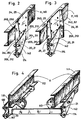
- in perspektivischer Darstellung im Ausschnitt ein erstes Befestigungselement, das über Schraubverbindungen am Tragrahmen des Fahrzeugs befestigbar ist,
- Fig. 3
- in perspektivischer Darstellung im Ausschnitt ein zweites Befestigungselement, das über Schraubverbindungen am Tragrahmen des Fahrzeugs befestigbar ist, wobei die hier gezeigte Ausführungsform des Befestigungselements für größere Belastungen ausgelegt ist als die in Fig. 2 dargestellte,
- Fig. 4
- in perspektivischer Darstellung im Ausschnitt eine Darstellung eines Teils des Ladebordwandsystems gemäß Fig. 1,
- Fig. 5
- ein Schema der Elemente des ersten Tragwerks und des zweiten Tragwerks sowie der daran angreifenden Hubzylindereinrichtung und der ein Teil des zweiten Tragwerks bildenden Klappzylindereinrichtung und
- Fig. 6
- in perspektivischer Darstellung das erste Tragwerk, gebildet aus zwei ersten Tragarmen sowie einem zweiten Tragarm, wobei der vordere erste Tragarm zum besseren Verständnis des konstruktiven Aufbaus des ersten Tragwerks teilweise im Ausschnitt dargestellt ist.
- 10
- Ladebordwandsystem
- 11
- Fahrzeug
- 110
- Tragrahmen
- 111
- Tragrahmen
- 12
- Hub- und Klapptragwerk
- 112
- horizontaler Steg
- 113
- horizontaler Steg
- 13
- erstes Tragwerk
- 130
- erster Tragarm
- 131
- erster Tragarm
- 132
- erste Drehachse
- 133
- zweite Drehachse
- 134
- zweiter Tragarm
- 135
- erstes Ende
- 136
- zweites Ende
- 137
- Drehachse
- 138
- Mittelebene
- 14
- zweites Tragwerk
- 140
- erster Tragarm
- 141
- erster Tragarm
- 142
- erste Drehachse
- 143
- zweite Drehachse
- 15
- Ladebordwand
- 16
- Hubzylindereinrichtung
- 160
- erstes Ende
- 161
- zweites Ende
- 162
- Drehachse
- 17
- Klappzylindereinrichtung
- 170
- erstes Ende
- 171
- zweites Ende
- 172
- Drehachse
- 173
- Längsachse
- 174
- Drehachse
- 18
- Ebene (erstes Tragwerk)
- 19
- Ebene (zweites Tragwerk)
- 20
- Befestigungselement
- 200
- Knick- oder Kantlinie
- 201
- erstes Teil
- 202
- zweites Teil
- 203
- freies Ende
- 21
- Befestigungselement
- 210
- Knick- oder Kantlinie
- 211
- erstes Teil
- 212
- zweites Teil
- 213
- freies Ende
- 23
- Klemmelement
- 24
- Verbindungselement
- 240
- erster Schenkel
- 241
- freies Ende
- 242
- zweiter Schenkel
- 25
- Verbindungselement
- 250
- erster Schenkel
- 251
- freies Ende
- 252
- zweiter Schenkel
- 26
- Winkelprofil
- 27
- Winkelprofil
Claims (16)
- Ladebordwandsystem (10) zur Befestigung an Fahrzeugen (11), insbesondere Lastkraftfahrzeugen, umfassend jeweils ein im wesentlichen parallelogrammförmiges, aus zwei im wesentlichen parallel voneinander beabstandeten Tragwerken'(13, 14) bestehendes Hub- und Klapptragwerk (12), eine im wesentlichen plattenförmige Ladebordwand (15) zum Heben und Absenken einer Last und zum Verschließen eines Stauraumes des Fahrzeuges (11) und eine Hubzylindereinrichtung zum Heben und Senken der Ladebordwand (15) sowie eine Klappzylindereinrichtung (17) zum Verschwenken der Ladebordwand (15) von der Horizontalen in die Vertikale und umgekehrt, dadurch gekennzeichnet, daß die Befestigung des ersten und des zweiten Tragwerks (13, 14) am Fahrzeug (11) über jeweils ein gesondertes Befestigungselement (20, 21) erfolgt.
- Ladebordwandsystem nach Anspruch 1, dadurch gekennzeichnet, daß das Befestigungselement (20, 21) eine plattenförmige Struktur aufweist.
- Ladebordwandsystem nach einem oder beiden der Ansprüche 1 oder 2, dadurch gekennzeichnet, daß das Befestigungselement (20, 21) längs einer im an das Fahrzeug (11) angebauten Zustand im wesentlichen vertikal verlaufenden Knick- oder Kantlinie (200, 210) mit einem ersten Teil (201, 211) in Richtung auf den Tragrahmen (110, 111) des Fahrzeugs (11) zu verläuft und mit einem zweiten Teil (202, 212), an dem das Tragwerk (13, 14) befestigt ist, im wesentlichen parallel zum Tragrahmen (110, 111) ausgerichtet ist, wobei zwischen beiden Teilen (201, 211; 202, 212) ein stumpfer Winkel α gebildet wird.
- Ladebordwandsystem nach einem oder mehreren der Ansprüche 1 bis 3, dadurch gekennzeichnet, daß das Befestigungselement (20, 21) mit dem Tragrahmen (110, 111) eines Fahrzeugs (11) über ein Verbindungselement (24, 25) fest verbindbar befestigbar ist.
- Ladebordwandsystem nach Anspruch 4, dadurch gekennzeichnet, daß das Verbindungselement (24, 25) eine plattenförmige Struktur aufweist.
- Ladebordwandsystem nach Anspruch 5, dadurch gekennzeichnet, daß das Verbindungselement (24, 25) wenigstens einen im wesentlichen quer zum Fahrzeug (11) ausgerichteten ersten Schenkel (240, 250) aufweist, wobei das Befestigungselement (20, 21) im Bereich seiner Knick- oder Kantlinie (200, 210) wenigstens mit dem freien Ende (241, 251) des Schenkels (240, 250) verbunden ist.
- Ladebordwandsystem nach Anspruch 6, dadurch gekennzeichnet, daß das Verbindungselement (24, 25) einen im wesentlichen quer zum Fahrzeug (11) ausgerichteten zweiten Schenkel (242, 252) aufweist, wobei das Befestigungselement (20, 21) mit dem freien Ende (203, 213) seines ersten Teils (201, 211), das abgewinkelt ausgebildet ist, mit dem zweiten Schenkel (242, 252) verbunden ist.
- Ladebordwandsystem nach einem oder mehreren der Ansprüche 1 bis 7, dadurch gekennzeichnet, daß die Befestigungselemente (20, 21) mit dem Tragrahmen (110, 111) eines Fahrzeugs (11) über klauenartig ausgestaltete Klemmelemente (22, 23), die über horizontale Stege (112, 113) des Tragrahmens (110, 111) des Fahrzeugs (11) greifen, lösbar befestigbar sind.
- Ladebordwandsystem nach einem oder mehreren der Ansprüche 1 bis 8, dadurch gekennzeichnet, daß die Kräfteeinleitungspunkte der Hubzylindereinrichtung (16) und/oder der Klappzylindereinrichtung (17) in das Hubund Klapptragwerk (12) jeweils in den durch die Drehpunkte A1, C1, D, E1 bzw. A2, B, C2, E2 gebildeten Ebenen (18, 19) der Elemente des jeweiligen ersten und/oder zweiten Tragwerks (13, 14) liegen, in der die Hubzylindereinrichtung (16) des ersten Tragwerks (13) und die Klappzylindereinrichtung (17) des zweiten Tragwerks (14) in bezug auf die von ihnen auf das Tragwerk (13) bzw. in dem Tragwerk (14) ausgeübten Kräfte einwirken.
- Ladebordwandsystem nach einem oder mehreren der Ansprüche 1 bis 9, dadurch gekennzeichnet, daß das erste Tragwerk (13) zwei im wesentlichen parallel voneinander beabstandete erste Tragarme (130, 131) umfaßt, wobei die ersten Tragarme (130, 131) über eine erste Drehachse (132) über die Befestigungselemente (20, 21) am Fahrzeug (11) drehbar befestigt sind und über eine zweite, am gegenüberliegenden Ende der ersten Tragarme (130, 131) angeordnete zweite Drehachse (133) mit einem ersten Ende (160) der Hubzylindereinrichtung (16) befestigt sind und wobei das zweite Ende (161) der Hubzylindereinrichtung (16) über eine Drehachse (162) drehbar über die Befestigungselemente (20, 21) am Fahrzeug (11) befestigt ist.
- Ladebordwandsystem nach einem oder mehreren der Ansprüche 1 bis 10, dadurch gekennzeichnet, daß das erste Tragwerk (13) einen zweiten Tragarm (134) umfaßt, der an seinem ersten Ende (135) mit den beiden ersten Tragarmen (130, 131) verbunden ist, wobei das zweite Ende (136) eine im wesentlichen orthogonal zu den beiden ersten Tragarmen (130, 131) verlaufende Drehachse (137) aufweist, über die der zweite Tragarm (134) drehbar mit der Ladebordwand (15) befestigt ist.
- Ladebordwandsystem nach Anspruch 11, dadurch gekennzeichnet, daß der zweite Tragarm (134) im wesentlichen in der Mittelebene (138) zwischen den beiden ersten Tragarmen (130, 131) ausgebildet ist.
- Ladebordwandsystem nach einem oder mehreren der Ansprüche 1 bis 12, dadurch gekennzeichnet, daß das zweite Tragwerk (14) zwei im wesentlichen parallel voneinander beabstandete erste Tragarme (140, 141) umfaßt, wobei die ersten Tragarme (140, 141) über eine erste Drehachse (142) über die Befestigungselemente (20, 21) am Fahrzeug (11) drehbar befestigt sind und über eine zweite, am anderen Ende der ersten Tragarme (140, 141) angeordnete zweite Drehachse (143), die im wesentlichen orthogonal zu den ersten Tragarmen (140, 141) und parallel zur ersten Drehachse (142) verläuft, drehbar mit der Ladebordwand (15) befestigt sind.
- Ladebordwandsystem nach einem oder mehreren der Ansprüche 1 bis 13, dadurch gekennzeichnet, daß die Klappzylindereinrichtung (17), die an ihrem ersten Ende (170) drehbar über die Befestigungselemente (20, 21) am Fahrzeug (11) befestigt ist, mit ihrem zweiten Ende (171) um eine Drehachse (172) im wesentlichen orthogonal zur Längsachse (173) der Klappzylindereinrichtung (17) drehbar mit der Ladebordwand (15) befestigt ist, wobei die Längsachse (173) im wesentlichen in der die Schwenkebene bildenden Ebene (19) des zweiten Tragwerks (14) verläuft.
- Ladebordwandsystem nach einem oder mehreren der Ansprüche 10 bis 14, dadurch gekennzeichnet, daß die Tragarme (130, 131; 140, 141) im wesentlichen plattenförmig ausgebildet sind.
- Ladebordwandsystem nach einem oder mehreren der Ansprüche 11 bis 15, dadurch gekennzeichnet, daß der zweite Tragarm (134) des ersten Tragwerks (13) im wesentlichen plattenförmig ausgebildet ist.
Priority Applications (1)
| Application Number | Priority Date | Filing Date | Title |
|---|---|---|---|
| DE59610634T DE59610634D1 (de) | 1996-05-21 | 1996-05-21 | Ladebordwandsystem |
Applications Claiming Priority (1)
| Application Number | Priority Date | Filing Date | Title |
|---|---|---|---|
| EP96108052A EP0808747B1 (de) | 1996-05-21 | 1996-05-21 | Ladebordwandsystem |
Related Parent Applications (1)
| Application Number | Title | Priority Date | Filing Date |
|---|---|---|---|
| EP96108052A Division EP0808747B1 (de) | 1996-05-21 | 1996-05-21 | Ladebordwandsystem |
Publications (2)
| Publication Number | Publication Date |
|---|---|
| EP1000802A1 EP1000802A1 (de) | 2000-05-17 |
| EP1000802B1 true EP1000802B1 (de) | 2003-07-30 |
Family
ID=8222802
Family Applications (4)
| Application Number | Title | Priority Date | Filing Date |
|---|---|---|---|
| EP00101236A Expired - Lifetime EP1000801B1 (de) | 1996-05-21 | 1996-05-21 | Ladebordwandsystem |
| EP00101238A Revoked EP1000803B1 (de) | 1996-05-21 | 1996-05-21 | Ladebordwandsystem |
| EP00101237A Expired - Lifetime EP1000802B1 (de) | 1996-05-21 | 1996-05-21 | Ladebordwandsystem |
| EP96108052A Expired - Lifetime EP0808747B1 (de) | 1996-05-21 | 1996-05-21 | Ladebordwandsystem |
Family Applications Before (2)
| Application Number | Title | Priority Date | Filing Date |
|---|---|---|---|
| EP00101236A Expired - Lifetime EP1000801B1 (de) | 1996-05-21 | 1996-05-21 | Ladebordwandsystem |
| EP00101238A Revoked EP1000803B1 (de) | 1996-05-21 | 1996-05-21 | Ladebordwandsystem |
Family Applications After (1)
| Application Number | Title | Priority Date | Filing Date |
|---|---|---|---|
| EP96108052A Expired - Lifetime EP0808747B1 (de) | 1996-05-21 | 1996-05-21 | Ladebordwandsystem |
Country Status (5)
| Country | Link |
|---|---|
| US (1) | US6082958A (de) |
| EP (4) | EP1000801B1 (de) |
| AT (2) | ATE198572T1 (de) |
| DE (1) | DE59606315D1 (de) |
| DK (1) | DK0808747T3 (de) |
Cited By (1)
| Publication number | Priority date | Publication date | Assignee | Title |
|---|---|---|---|---|
| EP1775158A1 (de) | 2005-10-13 | 2007-04-18 | Sörensen Hydraulik Zweigniederlassung, Ulfborg, Filial af Sörensen Hydraulik GmbH, Tyskland | Ladebordwandsystem zur Befestigung an Hilfsrahmen von Fahrzeugen |
Families Citing this family (23)
| Publication number | Priority date | Publication date | Assignee | Title |
|---|---|---|---|---|
| EP0930197B1 (de) | 1998-01-14 | 2002-10-30 | Sörensen Hydraulik, Zweigniederlassung, Ulfborg, Filial af Sörensen Hydraulik GmbH, Tyskland | Ladebordwandsystem mit einer fussbedienbaren Schalteinrichtung |
| DE19839058A1 (de) * | 1998-08-20 | 2000-02-24 | Gerd Baer | Hubladebühnensystem |
| EP0980786B2 (de) | 1998-08-20 | 2007-04-18 | Gerd Bär | Hublade-Bühnensystem |
| DE59806122D1 (de) * | 1998-08-21 | 2002-12-05 | Soerensen Hydraulik Ulfborg | Fahrzeugchassis mit Aufprallschutz für Fahrzeuge |
| DE59810358D1 (de) | 1998-12-17 | 2004-01-15 | Soerensen Hydraulik Ulfborg | Ladebordwandsystem mit wenigstens einem Hubaktuator |
| SI1018452T1 (en) | 1999-01-05 | 2003-10-31 | Soerensen Hydraulik, Zweigniederlassung, | Loading platform |
| IT1311742B1 (it) * | 1999-03-16 | 2002-03-19 | Campisa Srl | Sponda montacarichi ad elementi intercambiabili e sospensione diretta |
| DE59905942D1 (de) | 1999-12-10 | 2003-07-17 | Soerensen Hydraulik Ulfborg | Ladebordwandsystem |
| EP1118500A1 (de) | 2000-01-22 | 2001-07-25 | Sörensen Hydraulik Zweigniederlassung, Ulfborg, Filial af Sörensen Hydraulik GmbH, Tyskland | Ladebordwandsystem |
| EP1123835B1 (de) | 2000-02-10 | 2004-03-03 | Sörensen Hydraulik Zweigniederlassung, Ulfborg, Filial af Sörensen Hydraulik GmbH, Tyskland | Steuereinheit für Ladebordwandsysteme |
| EP1232903B1 (de) | 2001-02-14 | 2003-09-24 | Sörensen Hydraulik Zweigniederlassung, Ulfborg, Filial af Sörensen Hydraulik GmbH, Tyskland | Einrichtung zur Befestigung von Ladebordwandsystemen am Chassis-Rahmensystem von Anhängern, Sattelaufliegern und Fahrzeugen |
| US20040156705A1 (en) * | 2001-03-15 | 2004-08-12 | Karapet Ablabutyan | Unitary lift gate |
| EP1281568B1 (de) | 2001-08-01 | 2006-04-26 | Sörensen Hydraulik Zweigniederlassung, Ulfborg, Filial af Sörensen Hydraulik GmbH, Tyskland | Ladebordwandsystem zur Befestigung an Fahrzeugen |
| DE10205669C5 (de) * | 2002-02-12 | 2006-06-08 | Dautel Gmbh | Hubladebühnenvorrichtung für Fahrzeuge |
| US6685421B1 (en) | 2003-01-02 | 2004-02-03 | Charles N. Reeves | Hitch-mounted lift assembly |
| EP1502812B1 (de) | 2003-08-01 | 2006-04-26 | Gerd Bär | Hubladebühnensystem |
| EP1541412A1 (de) * | 2003-12-09 | 2005-06-15 | Sörensen Hydraulik Zweigniederlassung, Ulfborg, Filial af Sörensen Hydraulik GmbH, Tyskland | Ladebordwandsystem |
| EP1764263B1 (de) * | 2005-09-16 | 2008-11-12 | Sörensen Hydraulik, Zweigniederlassung, Ulfborg, Filial af Sörensen Hydraulik GmbH, Tyskland | Ladebordwandsystem zur Befestigung an Rahmen von Fahrzeugen |
| US7357263B2 (en) | 2006-03-22 | 2008-04-15 | Altec Industries, Inc. | Articulating jib |
| EP2384928B2 (de) | 2010-05-04 | 2019-03-13 | Sörensen Hydraulik, Zweigniederlassung, Ulfborg, Filial af Sörensen Hydraulik GmbH, Tyskland | Ladebordwandsystem |
| DE102013010526A1 (de) * | 2013-06-25 | 2015-01-08 | Mbb Palfinger Gmbh | Hubladebühne |
| CA3029512A1 (en) * | 2016-07-13 | 2018-01-18 | Nippon Steel & Sumitomo Metal Corporation | Hot-stamping formed article, structural member using the same, and manufacturing method of hot-stamping formed article |
| IT202200018945A1 (it) * | 2022-09-15 | 2024-03-15 | Anteo S P A | Sponda montacarichi per veicoli |
Family Cites Families (10)
| Publication number | Priority date | Publication date | Assignee | Title |
|---|---|---|---|---|
| GB641407A (en) * | 1948-09-14 | 1950-08-09 | W W Jenkins Cheltenham Ltd | Improvements in or relating to elevating mechanism primarily for vehicle tail boards |
| US2792135A (en) * | 1955-01-12 | 1957-05-14 | L A Young Spring & Wire Corp | Power-operated tail gate |
| US2850187A (en) * | 1956-01-17 | 1958-09-02 | Young Spring & Wire Corp | Tailgate mechanism for trucks |
| US2889059A (en) * | 1957-10-23 | 1959-06-02 | Selzer John | Power actuated tail gate elevator for motor vehicles |
| NL150067B (nl) * | 1972-11-01 | 1976-07-15 | Avo Intern Transport B V | Hefinrichting. |
| US3883014A (en) * | 1973-11-05 | 1975-05-13 | Heil Co | Tailgate lift mechanism |
| DE2654286A1 (de) * | 1976-11-30 | 1978-06-01 | Dautel Emil Kipperbau | Ladevorrichtung fuer lastfahrzeugaufbauten |
| DE3228829A1 (de) * | 1982-08-02 | 1984-02-09 | Emil Dautel GmbH, 7105 Leingarten | Ladevorrichtung fuer lastfahrzeugaufbauten |
| DE3228765A1 (de) * | 1982-08-02 | 1984-02-02 | Emil Dautel GmbH, 7105 Leingarten | Hubladebuehne fuer lastfahrzeuge |
| US5588793A (en) * | 1995-03-02 | 1996-12-31 | Chang; Hueng-San | Elevator mechanism for vehicle |
-
1996
- 1996-05-21 DE DE59606315T patent/DE59606315D1/de not_active Expired - Lifetime
- 1996-05-21 AT AT96108052T patent/ATE198572T1/de not_active IP Right Cessation
- 1996-05-21 DK DK96108052T patent/DK0808747T3/da active
- 1996-05-21 EP EP00101236A patent/EP1000801B1/de not_active Expired - Lifetime
- 1996-05-21 EP EP00101238A patent/EP1000803B1/de not_active Revoked
- 1996-05-21 AT AT00101237T patent/ATE246105T1/de not_active IP Right Cessation
- 1996-05-21 EP EP00101237A patent/EP1000802B1/de not_active Expired - Lifetime
- 1996-05-21 EP EP96108052A patent/EP0808747B1/de not_active Expired - Lifetime
-
1997
- 1997-01-23 US US08/788,813 patent/US6082958A/en not_active Expired - Fee Related
Non-Patent Citations (1)
| Title |
|---|
| "Super Mover 1500", Produktions AB Hydro Lift, Torshälla, Schweden * |
Cited By (1)
| Publication number | Priority date | Publication date | Assignee | Title |
|---|---|---|---|---|
| EP1775158A1 (de) | 2005-10-13 | 2007-04-18 | Sörensen Hydraulik Zweigniederlassung, Ulfborg, Filial af Sörensen Hydraulik GmbH, Tyskland | Ladebordwandsystem zur Befestigung an Hilfsrahmen von Fahrzeugen |
Also Published As
| Publication number | Publication date |
|---|---|
| ATE198572T1 (de) | 2001-01-15 |
| DE59606315D1 (de) | 2001-02-15 |
| DK0808747T3 (da) | 2001-05-07 |
| EP1000802A1 (de) | 2000-05-17 |
| ATE246105T1 (de) | 2003-08-15 |
| EP1000803A1 (de) | 2000-05-17 |
| EP1000803B1 (de) | 2003-08-20 |
| US6082958A (en) | 2000-07-04 |
| EP1000801A1 (de) | 2000-05-17 |
| EP1000801B1 (de) | 2003-11-26 |
| EP0808747B1 (de) | 2001-01-10 |
| EP0808747A1 (de) | 1997-11-26 |
Similar Documents
| Publication | Publication Date | Title |
|---|---|---|
| EP1000803B1 (de) | Ladebordwandsystem | |
| DE3419685A1 (de) | Mehrzweck-handkarren | |
| EP0097347A1 (de) | Geräteträger | |
| DE3015685A1 (de) | Lastenheber fuer paletten | |
| EP0784916A2 (de) | Fahrzeug zum Transport eines insbesondere fahrbaren Geräts | |
| EP0045398A1 (de) | Kombinierte Wechsel-Kipp-Einrichtung für Nutzfahrzeugaufbauten | |
| DE19905676A1 (de) | Zugdeichsel für Zentralachsanhänger | |
| DE19721121C2 (de) | Vorrichtung und Fahrzeug für Containertransport | |
| EP1541412A1 (de) | Ladebordwandsystem | |
| DE2947904C2 (de) | Vorrichtung zum wahlweisen Absetzen von transportablen Behältern, Maschinen oder Geräten auf der kippbaren Ladepritsche eines Lastfahrzeuges oder auf dem Boden | |
| DE4022854C2 (de) | Pritschenaufbau und Profilsystem zur Herstellung des Pritschenaufbaus | |
| DE69203075T2 (de) | Aufbau einer Heckklappe als Hebebühne. | |
| EP3571108B1 (de) | Rahmen eines kinderwagens | |
| CH673988A5 (de) | ||
| EP1106431B1 (de) | Ladebordwandsystem | |
| DE10351552B4 (de) | Fahrzeug für den Transport von Kurzholz und von Langholz | |
| DE19822809C2 (de) | Knickrahmengelenktes Ladefahrzeug | |
| EP2886393A1 (de) | Ladungssicherung für einen Aufbau eines Nutzfahrzeugs | |
| DE29624605U1 (de) | Ladebordwandsystem | |
| DE3111694C2 (de) | Fahrbarer Montagebock | |
| DE19516357A1 (de) | Anordnung bei Ladevorrichtungen für Transportfahrzeuge | |
| DE2630375C2 (de) | Türanordnung, insbesondere für Behälter, Behälterwagen o.dgl. | |
| EP2384928B1 (de) | Ladebordwandsystem | |
| DE29620358U1 (de) | Transportfahrzeug, insbesondere Lastkraftwagen oder Anhänger, mit einer Ladefläche und mit mindestens einer Auffahrrampe | |
| DE1289438B (de) | Lastfahrzeug, insbesondere Tieflader fuer den Transport von Fertigbauteilen |
Legal Events
| Date | Code | Title | Description |
|---|---|---|---|
| PUAI | Public reference made under article 153(3) epc to a published international application that has entered the european phase |
Free format text: ORIGINAL CODE: 0009012 |
|
| 17P | Request for examination filed |
Effective date: 20000218 |
|
| AC | Divisional application: reference to earlier application |
Ref document number: 808747 Country of ref document: EP |
|
| AK | Designated contracting states |
Kind code of ref document: A1 Designated state(s): AT BE DE DK FI FR GB IT NL SE |
|
| AKX | Designation fees paid |
Free format text: AT BE DE DK FI FR GB IT NL SE |
|
| 17Q | First examination report despatched |
Effective date: 20011218 |
|
| GRAH | Despatch of communication of intention to grant a patent |
Free format text: ORIGINAL CODE: EPIDOS IGRA |
|
| GRAH | Despatch of communication of intention to grant a patent |
Free format text: ORIGINAL CODE: EPIDOS IGRA |
|
| GRAA | (expected) grant |
Free format text: ORIGINAL CODE: 0009210 |
|
| AC | Divisional application: reference to earlier application |
Ref document number: 0808747 Country of ref document: EP Kind code of ref document: P |
|
| AK | Designated contracting states |
Designated state(s): AT BE DE DK FI FR GB IT NL SE |
|
| PG25 | Lapsed in a contracting state [announced via postgrant information from national office to epo] |
Ref country code: NL Free format text: LAPSE BECAUSE OF FAILURE TO SUBMIT A TRANSLATION OF THE DESCRIPTION OR TO PAY THE FEE WITHIN THE PRESCRIBED TIME-LIMIT Effective date: 20030730 Ref country code: FI Free format text: LAPSE BECAUSE OF FAILURE TO SUBMIT A TRANSLATION OF THE DESCRIPTION OR TO PAY THE FEE WITHIN THE PRESCRIBED TIME-LIMIT Effective date: 20030730 |
|
| REG | Reference to a national code |
Ref country code: GB Ref legal event code: FG4D Free format text: NOT ENGLISH |
|
| REF | Corresponds to: |
Ref document number: 59610634 Country of ref document: DE Date of ref document: 20030904 Kind code of ref document: P |
|
| PG25 | Lapsed in a contracting state [announced via postgrant information from national office to epo] |
Ref country code: DK Free format text: LAPSE BECAUSE OF FAILURE TO SUBMIT A TRANSLATION OF THE DESCRIPTION OR TO PAY THE FEE WITHIN THE PRESCRIBED TIME-LIMIT Effective date: 20031030 Ref country code: SE Free format text: LAPSE BECAUSE OF FAILURE TO SUBMIT A TRANSLATION OF THE DESCRIPTION OR TO PAY THE FEE WITHIN THE PRESCRIBED TIME-LIMIT Effective date: 20031030 |
|
| NLV1 | Nl: lapsed or annulled due to failure to fulfill the requirements of art. 29p and 29m of the patents act | ||
| GBT | Gb: translation of ep patent filed (gb section 77(6)(a)/1977) |
Effective date: 20031127 |
|
| ET | Fr: translation filed | ||
| PLBE | No opposition filed within time limit |
Free format text: ORIGINAL CODE: 0009261 |
|
| STAA | Information on the status of an ep patent application or granted ep patent |
Free format text: STATUS: NO OPPOSITION FILED WITHIN TIME LIMIT |
|
| 26N | No opposition filed |
Effective date: 20040504 |
|
| PGFP | Annual fee paid to national office [announced via postgrant information from national office to epo] |
Ref country code: AT Payment date: 20080523 Year of fee payment: 13 |
|
| PGFP | Annual fee paid to national office [announced via postgrant information from national office to epo] |
Ref country code: IT Payment date: 20080506 Year of fee payment: 13 Ref country code: BE Payment date: 20080513 Year of fee payment: 13 |
|
| PGFP | Annual fee paid to national office [announced via postgrant information from national office to epo] |
Ref country code: GB Payment date: 20080430 Year of fee payment: 13 |
|
| PGFP | Annual fee paid to national office [announced via postgrant information from national office to epo] |
Ref country code: FR Payment date: 20090520 Year of fee payment: 14 |
|
| BERE | Be: lapsed |
Owner name: *SORENSEN HYDRAULIK ZWEIGNIEDERLASSUNG ULFBORG FIL Effective date: 20090531 |
|
| GBPC | Gb: european patent ceased through non-payment of renewal fee |
Effective date: 20090521 |
|
| PG25 | Lapsed in a contracting state [announced via postgrant information from national office to epo] |
Ref country code: AT Free format text: LAPSE BECAUSE OF NON-PAYMENT OF DUE FEES Effective date: 20090521 |
|
| PG25 | Lapsed in a contracting state [announced via postgrant information from national office to epo] |
Ref country code: GB Free format text: LAPSE BECAUSE OF NON-PAYMENT OF DUE FEES Effective date: 20090521 |
|
| PG25 | Lapsed in a contracting state [announced via postgrant information from national office to epo] |
Ref country code: BE Free format text: LAPSE BECAUSE OF NON-PAYMENT OF DUE FEES Effective date: 20090531 |
|
| REG | Reference to a national code |
Ref country code: FR Ref legal event code: ST Effective date: 20110131 |
|
| PG25 | Lapsed in a contracting state [announced via postgrant information from national office to epo] |
Ref country code: IT Free format text: LAPSE BECAUSE OF NON-PAYMENT OF DUE FEES Effective date: 20090521 |
|
| PG25 | Lapsed in a contracting state [announced via postgrant information from national office to epo] |
Ref country code: FR Free format text: LAPSE BECAUSE OF NON-PAYMENT OF DUE FEES Effective date: 20100531 |
|
| PGFP | Annual fee paid to national office [announced via postgrant information from national office to epo] |
Ref country code: DE Payment date: 20150731 Year of fee payment: 20 |
|
| REG | Reference to a national code |
Ref country code: DE Ref legal event code: R071 Ref document number: 59610634 Country of ref document: DE |