EP1000824B1 - Fahrzeugsicherungsanordnung - Google Patents
Fahrzeugsicherungsanordnung Download PDFInfo
- Publication number
- EP1000824B1 EP1000824B1 EP00103223A EP00103223A EP1000824B1 EP 1000824 B1 EP1000824 B1 EP 1000824B1 EP 00103223 A EP00103223 A EP 00103223A EP 00103223 A EP00103223 A EP 00103223A EP 1000824 B1 EP1000824 B1 EP 1000824B1
- Authority
- EP
- European Patent Office
- Prior art keywords
- control device
- theft
- control unit
- vehicle
- code
- Prior art date
- Legal status (The legal status is an assumption and is not a legal conclusion. Google has not performed a legal analysis and makes no representation as to the accuracy of the status listed.)
- Expired - Lifetime
Links
- 230000006870 function Effects 0.000 description 84
- 238000012360 testing method Methods 0.000 description 19
- 238000004891 communication Methods 0.000 description 12
- 230000007794 irritation Effects 0.000 description 8
- 239000007858 starting material Substances 0.000 description 6
- 230000015654 memory Effects 0.000 description 5
- 238000000034 method Methods 0.000 description 5
- 230000008569 process Effects 0.000 description 5
- 238000013475 authorization Methods 0.000 description 4
- 238000003745 diagnosis Methods 0.000 description 4
- 230000007257 malfunction Effects 0.000 description 4
- 238000011161 development Methods 0.000 description 3
- 238000012546 transfer Methods 0.000 description 3
- 230000005540 biological transmission Effects 0.000 description 2
- 238000002347 injection Methods 0.000 description 2
- 239000007924 injection Substances 0.000 description 2
- 238000003825 pressing Methods 0.000 description 2
- 239000013589 supplement Substances 0.000 description 2
- TVZRAEYQIKYCPH-UHFFFAOYSA-N 3-(trimethylsilyl)propane-1-sulfonic acid Chemical compound C[Si](C)(C)CCCS(O)(=O)=O TVZRAEYQIKYCPH-UHFFFAOYSA-N 0.000 description 1
- 230000008901 benefit Effects 0.000 description 1
- 230000008859 change Effects 0.000 description 1
- 230000002950 deficient Effects 0.000 description 1
- 230000001419 dependent effect Effects 0.000 description 1
- 238000013461 design Methods 0.000 description 1
- 238000010586 diagram Methods 0.000 description 1
- 230000008030 elimination Effects 0.000 description 1
- 238000003379 elimination reaction Methods 0.000 description 1
- 238000004049 embossing Methods 0.000 description 1
- 239000000446 fuel Substances 0.000 description 1
- 230000006872 improvement Effects 0.000 description 1
- 238000012544 monitoring process Methods 0.000 description 1
- 238000012545 processing Methods 0.000 description 1
- 230000000638 stimulation Effects 0.000 description 1
- 238000012549 training Methods 0.000 description 1
- 230000007704 transition Effects 0.000 description 1
- 230000001960 triggered effect Effects 0.000 description 1
- 238000012795 verification Methods 0.000 description 1
- 230000000007 visual effect Effects 0.000 description 1
Images


Classifications
-
- B—PERFORMING OPERATIONS; TRANSPORTING
- B60—VEHICLES IN GENERAL
- B60R—VEHICLES, VEHICLE FITTINGS, OR VEHICLE PARTS, NOT OTHERWISE PROVIDED FOR
- B60R25/00—Fittings or systems for preventing or indicating unauthorised use or theft of vehicles
- B60R25/20—Means to switch the anti-theft system on or off
- B60R25/24—Means to switch the anti-theft system on or off using electronic identifiers containing a code not memorised by the user
-
- B—PERFORMING OPERATIONS; TRANSPORTING
- B60—VEHICLES IN GENERAL
- B60R—VEHICLES, VEHICLE FITTINGS, OR VEHICLE PARTS, NOT OTHERWISE PROVIDED FOR
- B60R25/00—Fittings or systems for preventing or indicating unauthorised use or theft of vehicles
-
- B—PERFORMING OPERATIONS; TRANSPORTING
- B60—VEHICLES IN GENERAL
- B60R—VEHICLES, VEHICLE FITTINGS, OR VEHICLE PARTS, NOT OTHERWISE PROVIDED FOR
- B60R25/00—Fittings or systems for preventing or indicating unauthorised use or theft of vehicles
- B60R25/01—Fittings or systems for preventing or indicating unauthorised use or theft of vehicles operating on vehicle systems or fittings, e.g. on doors, seats or windscreens
- B60R25/04—Fittings or systems for preventing or indicating unauthorised use or theft of vehicles operating on vehicle systems or fittings, e.g. on doors, seats or windscreens operating on the propulsion system, e.g. engine or drive motor
-
- B—PERFORMING OPERATIONS; TRANSPORTING
- B60—VEHICLES IN GENERAL
- B60R—VEHICLES, VEHICLE FITTINGS, OR VEHICLE PARTS, NOT OTHERWISE PROVIDED FOR
- B60R16/00—Electric or fluid circuits specially adapted for vehicles and not otherwise provided for; Arrangement of elements of electric or fluid circuits specially adapted for vehicles and not otherwise provided for
- B60R16/02—Electric or fluid circuits specially adapted for vehicles and not otherwise provided for; Arrangement of elements of electric or fluid circuits specially adapted for vehicles and not otherwise provided for electric constitutive elements
- B60R16/03—Electric or fluid circuits specially adapted for vehicles and not otherwise provided for; Arrangement of elements of electric or fluid circuits specially adapted for vehicles and not otherwise provided for electric constitutive elements for supply of electrical power to vehicle subsystems or for
- B60R16/0315—Electric or fluid circuits specially adapted for vehicles and not otherwise provided for; Arrangement of elements of electric or fluid circuits specially adapted for vehicles and not otherwise provided for electric constitutive elements for supply of electrical power to vehicle subsystems or for using multiplexing techniques
Definitions
- the invention is based on a fuse arrangement the genus of the main claim. Such an arrangement is known from FR-A-2,613,933.
- Another fuse arrangement (WO 93/05 987) consists of a Commissioning device with a code carrier and one Device for reading the code carrier, one with this connected data bus as well as several with the data bus connected units for controlling vehicle functions. To put the latter into operation, sends the reader a code signal, which they with a compares previously stored reference code. Agree at least one function control device from the Reading unit received and the previously saved Reference code does not match, it is entered via the data bus Error signal which, depending on the meaning of the affected Device for the vehicle functions to stop the vehicle leads.
- the object of the present invention is a Specify vehicle security arrangement, which at Ensuring equivalent protection against Inadmissible use of the simplest possible hardware structure and easily as a whole or for Improvement of existing security arrangements existing vehicles can be retrofitted.
- Control units carried out a data exchange to the Data line between the central control unit and Monitor function control devices. Occurs during the Operating an error, an error message is advisable generated, which in a permanent memory for later reading is filed.
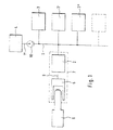
- FIG. 1 shows a block diagram of a Vehicle security arrangement
- Figure 2 a circuit implementation of the connection of a external device to the vehicle safety arrangement
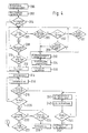
- Figure 3 the function of the central anti-theft control device in Form of a flow chart
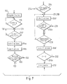
- Figure 4 the corresponding Function of the function control device in the form of a Flow charts
- Figure 1 shows the main components of a Vehicle security arrangement.
- DSS Anti-theft control device 2
- All function control devices 3, 3 ', 3 '' and the central anti-theft control device 2 each via at least one digital signal processing integrated circuit 29, 39, 39 ', 49, in particular in the form of a microprocessor or user-specific integrated circuit (ASIC), which on the one hand is used to carry out communication with the other control units including the Anti-theft control device, and which on the other hand performs device-specific functions, such as in In the case of the engine control unit, the determination of the amount of fuel to be injected, ignition control, etc.
- Other control devices of this type are in addition to the above Motor control device such as a transmission control 3 'or a Anti-lock / anti-slip control system 3 ''.
- the data line 1 has an interface in simple way in the form of a plug for connecting a external device 4.
- a device can in particular a tester for diagnosing control units 2, 3, 3 ', 3' 'or an application device for implementing new software in the control units 2, 3, 3 ', 3' '.
- the external device 4 is with the connector 10 expediently via a data line 1 ' connected, which the vehicle-side data line 1 continues.
- the vehicle-side data line 1 particularly preferred that in numerous vehicles anyway Existing diagnostic line according to ISO standard 9141. Physically, it is either one Line, the so-called K-line, or a pair of lines, a K line and an L line.
- To the existing one Diagnostic line according to ISO standard 9141 is also the Anti-theft control device 2 connected.
- FIG. 2 shows how, if an existing K line is used as data line 1, the theft protection device 2 and an external device 4 can be connected to data line 1 at the same time.
- both the anti-theft control device 2 and the external device 4 each have a resistor 21 or 41, the value of which according to ISO standard 9141 is 500 ohms, and switching means 22 or 42, usually in the form of transistors, existing series circuit, which is arranged between the potential of the vehicle battery voltage U B and ground.
- the switching means 22, 42 are each actuated by the circuit 29, 49 that processes digital signals in the associated control device 2, 4. Depending on the switching state, there is a "high” or a "low” level on the data line 1, 1 '.
- the series circuit 21, 22 additionally has a switch 23 which allows disconnection from the battery voltage U B.
- the electronic structure indicated in FIG. 2 can of course also be used for implementations that are not based on the use of the K or K and L diagnostic line.
- a vehicle to be secured is initially in Rest. Becomes a code carrier from this position 6 inserted into the reading device 5, step 100 this via the data line 9 a signal to the Anti-theft control device 2, which is then in a resets the defined starting position, step 102.
- the reset can be done by increasing the Supply voltage triggered after switching on the ignition become.
- Step 104 this checks Anti-theft control device 2, step 104, whether in a, expediently in the circuit 29 in the form of a permanent RAM or of an existing EEPROM permanent storage Unlocking information, which indicates that the Vehicle safety arrangement has been properly unlocked, is available. It is further assumed that the Unlocking information by setting a Unlock bits are given. As a rule, it is not set, whereupon the theft protection control device 2 in Step 106 first blocks the motor starter. Subsequently, Step 108, it checks the commissioning authorization of the Code carrier 6 handling user. This happens in the Usually by comparing the arranged on the code carrier 6 Codes with a previously in the reader 5 or in Anti-theft control device stored code.
- the anti-theft control device 2 expediently generates Step 107 a for locking the function control device 3 leading signal.
- the result is the Commissioning authorization check positive, unlocks the anti-theft control device 2, step 110, and then gives free the starter, step 112.
- the provisional release of the starter is included Data exchange for unlocking the engine control unit 3 on.
- the anti-theft control device 2 forms Step 114 first an unlocking base code Z, preferably in the form of a random number. From this it derives further, preferably by using a pre-stored algorithm on the base code Z one Unlock code Y from.
- Theft protection control unit 2 also checks, step 116, whether the ignition was switched on in a simple manner Check whether an ignition contact has been closed. Was the Ignition switched on, it sends the codes Z in step 118 and Y to the function control device 3. In the following Step 120 checks if there is irritation from an external Device 4 is present on data line 1. Usually lies no such signal before.
- the anti-theft control device 2 then checks in step 122 whether the function control device 3 an acknowledgment signal indicating correct unlocking was sent back. If there is an acknowledgment signal, sets the unlock bit in step 124. This was done correct start-up of the vehicle is up to the user appropriately displayed by, for example, one during the Unlock phase illuminating control lamp in step 126 is turned off.
- the central anti-theft control device 2 checks cyclically Step 128 whether irritation from an external device 4 is present data line 1 is present. There is no such signal before, it checks in step 130 whether the end of the Signal indicating vehicle operation is present by in particular the user has switched off the ignition. is the result of this test is negative, that is, the Vehicle operation continues, step 124 repeated up to 130 cycles.
- step 130 If the result of the test in step 130 is positive, lies a signal indicating the end of vehicle operation the theft protection control device 2 starts a counter, which by counting up to a predetermined value Follow-up time window defined. Whose size is expediently about 1 to 3 seconds. Then it checks in Step 132 whether the ignition has been switched on again. is the result is negative, it checks in step 134 whether the Follow-up time, i.e. the previously started time window has expired. If this has not yet happened, the Steps 132 and 134 repeated. Is the time window has expired, the anti-theft control unit 2 locks in step 136, wherein the unlock bit is reset. In turn, this condition is useful to the user optically, for example by one arranged in the vehicle Control lamp displayed, which for example slowly flashes. In this case the vehicle is intended shut down and locked.
- Step 118 Simultaneously with the sending of the codes Z and Y to the Function control device 3 in step 118 starts this Anti-theft control device 2 another time window, which is expediently 5 to 20 seconds.
- Step 122 receives an acknowledgment signal from the function controller 3 not yet, checks the anti-theft device 2 in next step 123, whether that started in step 118 Time window has already expired. This is not the case, it repeats steps 118 through 123. Is the time window expired, it signals this to the user expediently optically, for example by one arranged in the vehicle Luminaire that flashes quickly, for example.
- step 127 the anti-theft control device 2 checks whether the ignition was turned off. Is the result of this test negative, that means the ignition is unchanged on, it repeats steps 125 and 127 until the ignition is switched off. After that it locks in step 129.
- connection of a motor tester 4 means the establishment of a parallel, low-resistance connection of the data line 1, 1 'to the battery voltage U B in the anti-theft control device 2. This can lead to undefined signals on the data line 1, 1 'with regard to the communication taking place thereon and thus to malfunctions. The unlocking communication must therefore be completed before the control function is taken over the data line 1, 1 'by an external device.
- the external device 4 conducts expediently immediately after connection to data line 1 taking control of communication on the Data line 1 on. It also feeds a stimulus signal to the Data line 1, which from the anti-theft control device 2nd and function control unit 3 is recognized.
- the stimulus signal is appropriately a 200 millisecond long low level signal, corresponding to a stimulation with 5 Baud.
- the anti-theft control device 2 determines in step 128 that communication with the function control device 3 has been completed in accordance with regulations, that there is an irritation from a motor tester or another external device 4, in step 152 it disconnects the resistor 21 from the battery voltage U B and by means of the switch 23 transfers control of the data exchange via the data line 1, 1 'to the engine tester 4, step 154.
- Step 200 When switching on the ignition, generally realized by making a contact, that goes to that Function control unit 3 a corresponding signal.
- the Function control device 3 then settles in step 200 first return to a specified initial state.
- the Engine control function for example the injection control function temporarily free.
- the subsequent step 204 it checks whether in a Permanent storage, which in turn is useful as permanent RAM or EEPROM is executed, an unlock bit is set is. This is usually not the case. Thereupon follows in the next step 206 the check whether the anti-theft control device 2 an unlock code, consisting received from the codes Z and Y formed in step 114 has been.
- step 214 an unlock bit is set.
- the vehicle is now in Normal function, step 216 operated. It was unlocked properly.
- Function control device 3 a counter by counting up defines a time window up to a predetermined number.
- the counter can also start earlier, for example in Step 202.
- the purpose of the time window is to prevent an unlawful user from having enough time for manipulating the safety device.
- step 206 or 208 If the check in step 206 or 208 reveals that a code was not received or the checksum was wrong the function control device 3 checks in step 205 whether there is irritation from an engine tester 4. Is this if not, it checks in step 207 whether the engine is one has exceeded the specified speed threshold.
- the Speed threshold preferably corresponds to the so-called Starting speed, i.e. a characteristic speed, that the engine should have reached at the end of the starting phase.
- the function control unit 3 starts one at the same time another counter, which is counted up to one predefined number defines a second time window. His Length is chosen, for example one second, that a unlawful user of the vehicle by pressing the Starters cannot move a long distance.
- the function control unit checks 3 in step 209, whether the second, in step 207 started time window has expired. As long as not is done, steps 206, 205, 207 and 209 repeated. Malfunctions occur during engine start and if the engine does not reach the speed threshold, with the engine stopped, check whether the first, larger Time window of, for example, 3 seconds has expired, Step 211. If not, follow the steps 206, 205, 207, 211 repeated.
- the two time steps with a counter in steps 209 and 211 realize, is that the first time window only run as long as the engine speed is 0. Becomes the speed is greater than 0, or certain changes the vehicle electrical system voltage is recognized, the counter is reset started.
- step 205 If the check in step 205 reveals that a stimulus by a If the engine tester 4 is present, the function control unit 3 switches its functions in whole or in part, step 232, so that the engine tester functions may only be are available to a limited extent, step 234. It sets further in step 236 the unlock bit is back and stores a corresponding status message in a permanent memory, which can be read out, for example, using an engine tester.
- step 218 the function control unit 3 determines that an irritation from a motor tester on data line 1, 1 ', it executes steps 240 to 244, which executed by the anti-theft control device 2 Correspond to steps 154 to 158. Provides it in step 244 determines that the ignition has been switched off, sets it analogously to step 160 an unlock bit, step 246, which one one or more times according to the specified number Commissioning of the vehicle permitted without verification of legitimacy. If the check in step 204 reveals that a Unlock bit is set, the function control unit 3 immediately exits step 214 and sends in Acknowledgment signal to the anti-theft device 2. For When the normal operation ends, the steps close 220, 222, 224, and 226, which follow steps 130 through 136 in Figure 3 correspond.
- step 232 can do a check before performing step 232 be provided whether the engine speed below a predetermined limit. Only if this is the case the lock is executed, otherwise the function maintained.
- FIGS. 3 and 4 An advantageous development based on FIGS. 3 and 4 described arrangement is the Switch-off routine according to steps 132, 134, 136 in FIG 3 or 222 to 226 in Figure 4 by measures for Supplement diagnosis of data line 1.
- Such Supplement is in Figure 5 for the side of the Anti-theft control device 2, in Figure 6 for the side of the Function control device 3 shown.
- step 306 reveals that the time window has expired, it is checked in the next step 308 whether this line bit designating the state of the data line 1 was set. If so, send that Anti-theft control device 2 in step 310 Lock signal to the function control unit 3 and checks in the next step 312 whether this is an acknowledgment signal has arrived. If the result of this test is positive, follows in step 136 the termination of vehicle operation by resetting the unlocking bit and visual display by a lamp arranged in the vehicle.
- step 302 If the theft protection control device 2 determines in step 302, that an acknowledgment signal is not on the line test signal is present, it first checks in step 303 whether one with the Transmission of the line test signal started in step 300 Time window has expired. This is not the case, it repeats step 302 first and then optionally step 303.
- step 303 reveals that the time window has expired, there is an error in data line 1.
- the anti-theft control device 2 therefore sets this Line bit back. It then executes step 306. Is the line bit in the even after the time window Reset step 306, this locks Anti-theft control device 2 following step 308 in step 314. It shows the faulty line state expedient to the vehicle user optically. This can again, for example, by a lamp arranged in the vehicle happen which in a given way flashes.
- FIG. 6 shows that shown in FIG. 5 Flowchart corresponding processes on the side of the Function control unit 3.
- Step 220 After switching off the ignition in Step 220 first checks this in step 320 whether a Line test signal from anti-theft control device 2 was received. If so, it sends, step 322, an acknowledgment signal. This is checked in the next step 324 Function control unit 3, whether a locking signal from Anti-theft control device 2 was received. This step it also runs when the result of the test in step 320 is negative. If no lock signal was received, it checks in step 328 whether one with step 220 Started time window, the length of which is expedient 1 to 3 Seconds, has expired, and repeats the Steps 320 through 328 if not. Is this The result of the test in step 328 is positive Line failure. The injection control unit 3 unlocks therefore in step 330 for a predetermined number, for Example 3, from follow-up starts to at least one user provisional continued use of the vehicle enable.
- step 324 if the check in step 324 shows that a Lock signal was received, that sends Function control device 3 in step 326 first Acknowledgment signal to the anti-theft control device 2 and locks in step 226.
- Another advantageous development based on the Figures 3 and 4 described arrangement is a Line diagnosis not only after the end of the Normal operation by switching off the ignition, but to be carried out continuously during vehicle operation.
- This can be done in a simple manner, for example by that the anti-theft control device 2 following the Step 130 executes steps 118 and 122, respectively.
- Theft protection control device 2 stores in this case a permanent memory present in the circuit 29 corresponding error message, but does not lock. Instead, it saves after saving the Error message nevertheless continues through steps 124.
- step 114 is omitted, instead it checks in one Step 1161 whether the base code Z from the function control device 3 received, forms, if this has happened, then in step 114a from base code Z one Unlock code Y and sends it similarly to step 118 back to the function controller, step 118a. Arrives Base code Z is not a, the query in step 1161 in can be easily repeated. Likewise, for this In case, however, more complex measures can be provided, such as for example a repetition of the Step 1161 with subsequent locking.
- the function control device 3 checks whether the Anti-theft control device 2 unlocking code Y has arrived. To do this, it forms itself expediently same way as the anti-theft control device 2 one Unlock code Y ', step 2081, and compares it, similar to step 210, with the code Y obtained, step 210a.
- Function control device 3 also advantageous if this not only performs the generation of the base code 7, but generally the control function via the data line 1 exercises.
- the function control device 3 requests this If there is an immediate re-authentication, to regenerate the unlock bit.
- Another useful training of the previous described system which, however, also in connection with many other known vehicle safety devices is advantageous, is the possibility to provide an unlock code bypassing the Anti-theft control device 2 to enter if, for example an acknowledgment signal in step 123 after the time window has expired from the function control unit 3 is not yet available.
- the theft control device 2 signals this User preferably via a lamp or a display, a code for unlocking the function control unit 3 manually bypassing data line 1. This can, for example, by a predetermined sequence of operations of the accelerator pedal, which the function control device 3rd then recognizes.
- the code can, for example Vehicle-specific in one in the function control unit stored existing permanent storage and / or the Vehicle owners, for example, by embossing them in the code carrier 6 or entry in the vehicle registration letter.
- the function control device 3 checks whether the Unlocking code was entered correctly. Is this the Case, it sets the unlock bit and then drives as in normal operation. On the other hand, does it find that a Unlock code was not entered or was entered incorrectly, it locks according to steps 232 through 236.
- the possibility of entering the unlock code manually enables a vehicle to be put into operation even if the data line 1 between the theft control device 2 and the function control device 3 is damaged. it increases but again the risk of manipulation. To that To counteract this, it is advisable to enter the Unlocking codes bypassing data line 1 only allow if previously in an operating state after proper unlocking as part of a Line diagnostics a fault condition is determined and a corresponding information has been saved.
- the proposed principle for implementing the Legitimacy check which is the control function exercising control unit 2, 3, 3 ', 3' 'a base code Z and an unlocking code Y derived therefrom to another Control unit 2, 3, 3 ', 3' 'sends this in the same way like the sending control unit from the base code Unlocking code Y 'and then both codes Y, Y 'compares is in many other security arrangements usable on a data exchange between two Control devices for authentication are based.
Landscapes
- Engineering & Computer Science (AREA)
- Mechanical Engineering (AREA)
- Lock And Its Accessories (AREA)
- Selective Calling Equipment (AREA)
Description
Claims (1)
- Sicherungsanordnung für ein Kraftfahrzeug mit einem Diebstahlschutzsteuergerät (2), das einen Datenaustausch mit wenigstens einem Funktionssteuergerät (3, 3', 3'') führt, um dessen Betriebsbereitschaft zu steuern, sowie einer wenigstens das Diebstahlschutzsteuergerät (2) und das Funktionssteuergerät (3, 3', 3'') verbindenden Datenleitung (1), über welche der Datenaustausch erfolgt, wobei im Falle eines fehlerhaften Datenaustausches zwischen Diebstahlschutzsteuergerät (2) und Funktionssteuergerät (3, 3', 3'') ein Code zur Entriegelung der Steuergeräte (3, 3', 3'') unter Umgehung des Diebstahlschutzsteuergeräts (2) manuell eingebbar ist, dadurch gekennzeichnet, daß die Eingabe des Entriegelungscodes unter Umgehung der Datenleitung (1) nur zugelassen wird, wenn zuvor in einem Betriebszustand nach ordnungsgemäßer Entriegelung im Rahmen einer Leitungs diagnose ein Fehlerzustand festgestellt und eine entsprechende Information abgespeichert wurde.
Applications Claiming Priority (5)
| Application Number | Priority Date | Filing Date | Title |
|---|---|---|---|
| DE4336938 | 1993-10-29 | ||
| DE4336938 | 1993-10-29 | ||
| DE4414644 | 1994-04-27 | ||
| DE4414644A DE4414644A1 (de) | 1993-10-29 | 1994-04-27 | Fahrzeugsicherungsanordnung |
| EP94928762A EP0725743B1 (de) | 1993-10-29 | 1994-10-11 | Fahrzeugsicherungsanordnung |
Related Parent Applications (1)
| Application Number | Title | Priority Date | Filing Date |
|---|---|---|---|
| EP94928762A Division EP0725743B1 (de) | 1993-10-29 | 1994-10-11 | Fahrzeugsicherungsanordnung |
Publications (2)
| Publication Number | Publication Date |
|---|---|
| EP1000824A1 EP1000824A1 (de) | 2000-05-17 |
| EP1000824B1 true EP1000824B1 (de) | 2003-05-21 |
Family
ID=6501320
Family Applications (2)
| Application Number | Title | Priority Date | Filing Date |
|---|---|---|---|
| EP00103223A Expired - Lifetime EP1000824B1 (de) | 1993-10-29 | 1994-10-11 | Fahrzeugsicherungsanordnung |
| EP00103136A Expired - Lifetime EP1000823B1 (de) | 1993-10-29 | 1994-10-11 | Fahrzeugsicherungsanordnung |
Family Applications After (1)
| Application Number | Title | Priority Date | Filing Date |
|---|---|---|---|
| EP00103136A Expired - Lifetime EP1000823B1 (de) | 1993-10-29 | 1994-10-11 | Fahrzeugsicherungsanordnung |
Country Status (4)
| Country | Link |
|---|---|
| EP (2) | EP1000824B1 (de) |
| KR (1) | KR100350007B1 (de) |
| DE (1) | DE4414644A1 (de) |
| RU (1) | RU2133680C1 (de) |
Families Citing this family (26)
| Publication number | Priority date | Publication date | Assignee | Title |
|---|---|---|---|---|
| DE4427084A1 (de) * | 1994-07-30 | 1996-02-01 | Bosch Gmbh Robert | Fahrzeugsicherungsanordnung |
| DE19502373C2 (de) * | 1995-01-26 | 1997-07-03 | Telefunken Microelectron | Verfahren zur Diebstahlsicherung motorangetriebener Kraftfahrzeuge |
| DE19505871A1 (de) | 1995-02-21 | 1996-08-22 | Bosch Gmbh Robert | Fahrzeugsicherungseinrichtung |
| DE19520505A1 (de) * | 1995-06-03 | 1996-12-05 | Bosch Gmbh Robert | Wegfahrsperre |
| DE19525180C5 (de) | 1995-07-11 | 2010-01-07 | Daimler Ag | Elektronisches Steuergerät für ein Kraftfahrzeug mit Datennetzwerken und Wegfahrsperre |
| DE19533191B4 (de) * | 1995-09-08 | 2006-01-05 | Kiekert Ag | Verfahren zum Neueinrichten einer Zentralverriegelungsanlage eines Kraftfahrzeuges mit einer Fernbetätigungseinrichtung |
| US5796179A (en) * | 1995-09-30 | 1998-08-18 | Suzuki Motor Corporation | Vehicle anti-theft device with low voltage compensation and a rolling code |
| DE19637657A1 (de) * | 1996-09-16 | 1998-03-19 | Bosch Gmbh Robert | Fahrzeugsicherungsanordnung |
| DE19958564B4 (de) * | 1999-12-04 | 2008-11-13 | Adam Opel Ag | Vorrichtung zur Sicherung von Kraftfahrzeugen gegen Manipulation |
| RU2176961C2 (ru) * | 2000-01-10 | 2001-12-20 | Открытое акционерное общество "АВТОВАЗ" | Способ обмена данными между блоком управления двс и иммобилайзером системы безопасности автомобиля |
| RU2176962C2 (ru) * | 2000-01-10 | 2001-12-20 | Открытое акционерное общество "АВТОВАЗ" | Система безопасности транспортного средства |
| RU2176963C2 (ru) * | 2000-02-09 | 2001-12-20 | Открытое акционерное общество "АВТОВАЗ" | Способ восстановления работоспособности системы безопасности автомобиля |
| DE10111286B4 (de) * | 2001-03-09 | 2005-04-21 | Audi Ag | Steuerungssystem und Verfahren zur Steuerung von Kraftfahrzeugkomponenten |
| DE10226253A1 (de) * | 2002-06-13 | 2004-01-08 | Robert Bosch Gmbh | Kommunikationsnetzwerk für ein Kraftfahrzeug und Verfahren zum Betrieb desselben |
| DE10332452B4 (de) * | 2003-07-17 | 2018-04-12 | Continental Teves Ag & Co. Ohg | Steuerungs- und Regelungsgerät in einem Kraftfahrzeug sowie Verfahren zum Betreiben desselben |
| DE102005028772A1 (de) * | 2005-06-22 | 2007-01-04 | Daimlerchrysler Ag | Verfahren zur Nutzungsberechtigungsfreigabe für ein Fahrzeug und zugehöriges Fahrberechtigungssystem |
| DE102007005068B3 (de) * | 2007-01-26 | 2008-05-29 | Audi Ag | Diebstahlsicherungssystem |
| KR100831924B1 (ko) | 2007-05-14 | 2008-05-23 | 유장호 | 차량 모니터링 장치 및 그 제어방법 |
| EP2112037A1 (de) * | 2008-04-25 | 2009-10-28 | Delphi Technologies, Inc. | Sicherheitsmodul |
| RU2422305C1 (ru) * | 2009-10-26 | 2011-06-27 | Государственное образовательное учреждение Высшего профессионального образования Поволжский государственный университет сервиса | Устройство защиты информации системы мониторинга, диагностики оборудования автомобиля |
| RU2421352C1 (ru) * | 2009-10-26 | 2011-06-20 | Государственное образовательное учреждение Высшего профессионального образования Поволжский государственный университет сервиса | Устройство защиты информации для систем управления оборудованием автомобиля |
| DE102009046434A1 (de) * | 2009-11-05 | 2011-06-01 | Robert Bosch Gmbh | Verfahren, Steuergerät und Aktuator zur Sicherung eines Kraftfahrzeugs |
| DE102009054167B4 (de) * | 2009-11-23 | 2025-08-28 | Marquardt Gmbh | Schließsystem für ein Kraftfahrzeug |
| EP2634251A1 (de) | 2012-02-29 | 2013-09-04 | Technische Universität Berlin | Dreidimensionales, zweiphasiges In-vitro-Knorpelknochenkonstrukt |
| EP2633870B1 (de) | 2012-02-29 | 2018-08-01 | Technische Universität Berlin | Verfahren zur Herstellung eines künstlichen Zahn-Primordiums und davon abgeleitetes künstliches Zahn-Primordium |
| DE102014014339B4 (de) * | 2014-09-27 | 2020-12-03 | Audi Ag | Betriebsverfahren für eine Wegfahrsperre |
Family Cites Families (22)
| Publication number | Priority date | Publication date | Assignee | Title |
|---|---|---|---|---|
| GB2051442B (en) * | 1979-03-30 | 1984-02-01 | Howard J A | Security system |
| DE3240773C2 (de) * | 1982-11-02 | 1986-06-05 | Jürgen 1000 Berlin Binder | Elektronische Überwachungsvorrichtung für die vom Fahrer eines Kraftfahrzeuges, insbesondere Lastkraftwagen oder Bus, abgeleistete Fahrzeit |
| FR2613993B1 (fr) * | 1987-04-17 | 1992-01-03 | Renault | Dispositif et procede d'antivol electronique d'un vehicule |
| DE3739670A1 (de) * | 1987-11-24 | 1989-08-24 | Opel Adam Ag | Modulares elektroniksystem insbesondere fuer kraftfahrzeuge |
| EP0407402A4 (en) * | 1988-02-18 | 1991-07-24 | Australian Security,Technology And Development Pty. Ltd | Security apparatus |
| US5006843A (en) * | 1988-12-01 | 1991-04-09 | Werner Hauer | Security module to preclude unauthorized users to operate motor driven equipment and to protect valuable parts of the motor from unauthorized exchange |
| EP0377816A3 (de) * | 1988-12-01 | 1991-05-22 | Werner Hauer | Ein Sicherheits-System für motorbetriebene Fahrzeuge mit im Motorzubehör eingebauten Schaltelementen |
| EP0392411B2 (de) * | 1989-04-14 | 1999-01-07 | Hitachi, Ltd. | Kontrollvorrichtung für Autos |
| JPH02293999A (ja) * | 1989-05-08 | 1990-12-05 | Clarion Co Ltd | 複数機器接続システムの盗難防止装置 |
| US5144667A (en) * | 1990-12-20 | 1992-09-01 | Delco Electronics Corporation | Method of secure remote access |
| DE4204463C2 (de) * | 1991-02-15 | 1995-06-01 | Alps Electric Co Ltd | Identifikations-Informations-Sende-/Empfangsvorrichtung |
| DE69216644T2 (de) * | 1991-09-17 | 1997-04-24 | Ford Werke Ag | Kraftfahrzeugsicherheitsystem |
| IT1249853B (it) * | 1991-10-18 | 1995-03-28 | Trw Sipea Spa | Telecomando per mezzi attuatori, in particolare di un autoveicolo. |
| DE4301436C2 (de) * | 1993-01-20 | 1996-06-13 | Kaiser Hans Christian | Sicherungssystem |
| DE4310098C2 (de) * | 1993-03-23 | 1998-01-15 | Blohberger Ralf | Verfahren und Einrichtung zur Erhöhung der Sicherheit gegen Diebstahl von als Leihwagen dienenden Kraftfahrzeugen |
| DE9308721U1 (de) * | 1993-06-11 | 1993-11-18 | Kizler Peter Dr | Diebstahlsicherung für Kraftfahrzeuge |
| IT1268471B1 (it) * | 1993-07-22 | 1997-03-04 | Gemini Elettronica | Sistema di sicurezza per veicoli |
| IT1260965B (it) * | 1993-08-06 | 1996-04-29 | Weber Srl | Dispositivo di controllo per un sistema antifurto per mezzi di locomozione |
| IT1260963B (it) * | 1993-08-06 | 1996-04-29 | Weber Srl | Dispositivo di sicurezza per un sistema antifurto per mezzi di locomozione |
| GB9320767D0 (en) * | 1993-10-08 | 1993-12-01 | British Tech Group | Vehicle security |
| DE4334859A1 (de) * | 1993-10-13 | 1994-12-01 | Daimler Benz Ag | Einrichtung zum Testen und/oder Programmieren von elektronischen Steuergeräten in einem Kraftfahrzeug |
| RU2076815C1 (ru) * | 1995-10-31 | 1997-04-10 | Совместное Российско-Шведское предприятие "Геософт-Истлинк" ("Геолинк") | Противоугонная система для транспортного средства |
-
1994
- 1994-04-27 DE DE4414644A patent/DE4414644A1/de not_active Ceased
- 1994-10-11 RU RU96110212A patent/RU2133680C1/ru not_active IP Right Cessation
- 1994-10-11 KR KR1019960702191A patent/KR100350007B1/ko not_active Expired - Fee Related
- 1994-10-11 EP EP00103223A patent/EP1000824B1/de not_active Expired - Lifetime
- 1994-10-11 EP EP00103136A patent/EP1000823B1/de not_active Expired - Lifetime
Also Published As
| Publication number | Publication date |
|---|---|
| EP1000824A1 (de) | 2000-05-17 |
| EP1000823B1 (de) | 2005-12-07 |
| DE4414644A1 (de) | 1995-05-04 |
| EP1000823A1 (de) | 2000-05-17 |
| RU2133680C1 (ru) | 1999-07-27 |
| KR100350007B1 (ko) | 2003-04-10 |
| KR960705705A (ko) | 1996-11-08 |
Similar Documents
| Publication | Publication Date | Title |
|---|---|---|
| EP0725743B1 (de) | Fahrzeugsicherungsanordnung | |
| EP1000824B1 (de) | Fahrzeugsicherungsanordnung | |
| DE19546775B4 (de) | Datenverarbeitungsgerät für Fahrzeug | |
| DE69633968T2 (de) | Diebstahlsicherungsvorrichtung für Kraftfahrzeuge | |
| EP0925209B1 (de) | Fahrzeugsicherungsanordnung | |
| DE102014101917A1 (de) | CAN-basierte Wegfahrsperre | |
| DE68912445T2 (de) | Elektronisches Diebstahlschutzsystem für Kraftfahrzeug. | |
| DE19880227C2 (de) | Schutzvorrichtung für Fehlererkennungs-Anschlüsse in verzweigten Computernetzen | |
| EP0642959B1 (de) | Diebstahlsicherung für ein Kraftfahrzeug | |
| DE4405708C2 (de) | Kraftfahrzeug mit Diebstahlsicherung durch Motorstartblockierung | |
| DE10015307B4 (de) | Verfahren und Vorrichtung zum Schutz eines Gerätes vor Diebstahl | |
| DE19960958B4 (de) | Vorrichtung zum Diebstahlschutz | |
| DE102005023818B4 (de) | Anzeigeeinheit für ein elektrifiziertes Schaltgetriebe in einem Fahrzeug | |
| EP0830273B1 (de) | Wegfahrsperre | |
| DE10338649B4 (de) | Kraftfahrzeug | |
| EP0734333B1 (de) | Wegfahrsperre mit kurzer entriegelungszeit | |
| DE4330733C2 (de) | Vorrichtung zur Diebstahlsicherung eines Kraftfahrzeuges | |
| DE102008011700B4 (de) | Verfahren und Vorrichtung zum Anlernen eines Funkschlüssels an ein Zugangssteuergerät für ein Kraftfahrzeug | |
| DE10323504A1 (de) | Vorrichtung und Verfahren zur Diebstahlsicherung eines Kraftfahrzeuges | |
| EP0728639B1 (de) | Verfahren zum Betrieb einer Fahrzeugsicherungseinrichtung | |
| EP1101672B1 (de) | Sicherungssystem für Kraftfahrzeuge | |
| DE102007012414A1 (de) | Elektronisches Fahrzeugsicherungssystem | |
| EP1892157A2 (de) | Steuergerät für ein Kraftfahrzeug und Verfahren zum Betrieb eines Steuergeräts für ein Kraftfahrzeug | |
| DE102006029361A1 (de) | Diagnoseverfahren für Verbraucher eines Kraftfahrzeugs sowie Diagnosevorrichtung zur Durchführung des Diagnoseverfahrens |
Legal Events
| Date | Code | Title | Description |
|---|---|---|---|
| PUAI | Public reference made under article 153(3) epc to a published international application that has entered the european phase |
Free format text: ORIGINAL CODE: 0009012 |
|
| AC | Divisional application: reference to earlier application |
Ref document number: 725743 Country of ref document: EP |
|
| AK | Designated contracting states |
Kind code of ref document: A1 Designated state(s): CH DE ES FR GB IT LI SE |
|
| 17P | Request for examination filed |
Effective date: 20001117 |
|
| AKX | Designation fees paid |
Free format text: CH DE ES FR GB IT LI SE |
|
| 17Q | First examination report despatched |
Effective date: 20011018 |
|
| GRAH | Despatch of communication of intention to grant a patent |
Free format text: ORIGINAL CODE: EPIDOS IGRA |
|
| GRAH | Despatch of communication of intention to grant a patent |
Free format text: ORIGINAL CODE: EPIDOS IGRA |
|
| GRAA | (expected) grant |
Free format text: ORIGINAL CODE: 0009210 |
|
| AC | Divisional application: reference to earlier application |
Ref document number: 0725743 Country of ref document: EP Kind code of ref document: P |
|
| AK | Designated contracting states |
Designated state(s): CH DE ES FR GB IT LI SE |
|
| PG25 | Lapsed in a contracting state [announced via postgrant information from national office to epo] |
Ref country code: IT Free format text: LAPSE BECAUSE OF FAILURE TO SUBMIT A TRANSLATION OF THE DESCRIPTION OR TO PAY THE FEE WITHIN THE PRE;WARNING: LAPSES OF ITALIAN PATENTS WITH EFFECTIVE DATE BEFORE 2007 MAY HAVE OCCURRED AT ANY TIME BEFORE 2007. THE CORRECT EFFECTIVE DATE MAY BE DIFFERENT FROM THE ONE RECORDED.SCRIBED TIME-LIMIT Effective date: 20030521 |
|
| REG | Reference to a national code |
Ref country code: GB Ref legal event code: FG4D Free format text: NOT ENGLISH |
|
| REG | Reference to a national code |
Ref country code: CH Ref legal event code: EP |
|
| REF | Corresponds to: |
Ref document number: 59410292 Country of ref document: DE Date of ref document: 20030626 Kind code of ref document: P |
|
| PG25 | Lapsed in a contracting state [announced via postgrant information from national office to epo] |
Ref country code: SE Free format text: LAPSE BECAUSE OF FAILURE TO SUBMIT A TRANSLATION OF THE DESCRIPTION OR TO PAY THE FEE WITHIN THE PRESCRIBED TIME-LIMIT Effective date: 20030821 |
|
| PG25 | Lapsed in a contracting state [announced via postgrant information from national office to epo] |
Ref country code: ES Free format text: LAPSE BECAUSE OF FAILURE TO SUBMIT A TRANSLATION OF THE DESCRIPTION OR TO PAY THE FEE WITHIN THE PRESCRIBED TIME-LIMIT Effective date: 20030901 |
|
| PG25 | Lapsed in a contracting state [announced via postgrant information from national office to epo] |
Ref country code: LI Free format text: LAPSE BECAUSE OF NON-PAYMENT OF DUE FEES Effective date: 20031031 Ref country code: CH Free format text: LAPSE BECAUSE OF NON-PAYMENT OF DUE FEES Effective date: 20031031 |
|
| GBT | Gb: translation of ep patent filed (gb section 77(6)(a)/1977) |
Effective date: 20031021 |
|
| PLBE | No opposition filed within time limit |
Free format text: ORIGINAL CODE: 0009261 |
|
| STAA | Information on the status of an ep patent application or granted ep patent |
Free format text: STATUS: NO OPPOSITION FILED WITHIN TIME LIMIT |
|
| ET | Fr: translation filed | ||
| 26N | No opposition filed |
Effective date: 20040224 |
|
| REG | Reference to a national code |
Ref country code: CH Ref legal event code: PL |
|
| PGFP | Annual fee paid to national office [announced via postgrant information from national office to epo] |
Ref country code: FR Payment date: 20121113 Year of fee payment: 19 |
|
| PGFP | Annual fee paid to national office [announced via postgrant information from national office to epo] |
Ref country code: GB Payment date: 20121023 Year of fee payment: 19 |
|
| PGFP | Annual fee paid to national office [announced via postgrant information from national office to epo] |
Ref country code: DE Payment date: 20121217 Year of fee payment: 19 |
|
| GBPC | Gb: european patent ceased through non-payment of renewal fee |
Effective date: 20131011 |
|
| REG | Reference to a national code |
Ref country code: DE Ref legal event code: R119 Ref document number: 59410292 Country of ref document: DE Effective date: 20140501 |
|
| PG25 | Lapsed in a contracting state [announced via postgrant information from national office to epo] |
Ref country code: GB Free format text: LAPSE BECAUSE OF NON-PAYMENT OF DUE FEES Effective date: 20131011 |
|
| REG | Reference to a national code |
Ref country code: FR Ref legal event code: ST Effective date: 20140630 |
|
| PG25 | Lapsed in a contracting state [announced via postgrant information from national office to epo] |
Ref country code: FR Free format text: LAPSE BECAUSE OF NON-PAYMENT OF DUE FEES Effective date: 20131031 Ref country code: DE Free format text: LAPSE BECAUSE OF NON-PAYMENT OF DUE FEES Effective date: 20140501 |