EP1000832B1 - Drehbarer Sitz, insbesondere für ein Schienenfahrzeug - Google Patents
Drehbarer Sitz, insbesondere für ein Schienenfahrzeug Download PDFInfo
- Publication number
- EP1000832B1 EP1000832B1 EP99402650A EP99402650A EP1000832B1 EP 1000832 B1 EP1000832 B1 EP 1000832B1 EP 99402650 A EP99402650 A EP 99402650A EP 99402650 A EP99402650 A EP 99402650A EP 1000832 B1 EP1000832 B1 EP 1000832B1
- Authority
- EP
- European Patent Office
- Prior art keywords
- pivot
- axis
- base
- movable
- seat according
- Prior art date
- Legal status (The legal status is an assumption and is not a legal conclusion. Google has not performed a legal analysis and makes no representation as to the accuracy of the status listed.)
- Expired - Lifetime
Links
- 238000005096 rolling process Methods 0.000 claims description 6
- 230000000295 complement effect Effects 0.000 claims description 2
- 230000000750 progressive effect Effects 0.000 claims 2
- 238000006073 displacement reaction Methods 0.000 description 7
- 230000000694 effects Effects 0.000 description 3
- 230000006835 compression Effects 0.000 description 1
- 238000007906 compression Methods 0.000 description 1
- 230000001419 dependent effect Effects 0.000 description 1
- 230000002787 reinforcement Effects 0.000 description 1
Images




Classifications
-
- B—PERFORMING OPERATIONS; TRANSPORTING
- B61—RAILWAYS
- B61D—BODY DETAILS OR KINDS OF RAILWAY VEHICLES
- B61D33/00—Seats
- B61D33/0057—Seats characterised by their mounting in vehicles
- B61D33/0078—Seats characterised by their mounting in vehicles adjustably mounted
- B61D33/0085—Seats characterised by their mounting in vehicles adjustably mounted rotatably
Definitions
- the present invention relates to a rotating seat, in particular for a railway vehicle.
- a seat of the type comprising a movable upper portion for receiving at least one occupant carried by a fixed lower portion forming a base and means for reversing the upper part from front to back and reciprocally.
- the seats of this type are arranged in particular in railway vehicles.
- the means for reversing a seat make it possible to reverse the front-rear orientation of this seat so as to place this seat and the passenger (s) occupying it (s) in the direction of movement of the vehicle. , whatever the direction in which this vehicle travels a path.
- the seats of a railway vehicle are arranged near a left or right side wall of this vehicle.
- the space between the seats and the neighboring side wall is preferably as small as possible, the movement of a seat back and forth (and vice versa) by a simple rotation of the movable upper part of the seat around a fixed vertical axis is obstructed by the side wall. Therefore, generally the reversal of a seat is achieved, firstly, by removing the movable upper portion of the adjacent wall of the seat, then rotating the movable portion about a vertical axis and finally bringing this mobile part of the wall next to the seat.
- No. 1,735,321 discloses a seat according to the preamble of claim 1.
- the object of the invention is to propose a seat, in particular for a railway vehicle, provided with bulky reversing means which are light and simple to maneuver in order to enable the front-to-rear orientation of all the seats to be reversed quickly. a railway vehicle.
- the subject of the invention is a seat according to claim 1.
- the invention also relates to a railway vehicle comprising a seat as defined above.
- FIG. 1 shows a seat 10, according to the invention, arranged in a railway vehicle 12.
- the seat 10 has a movable upper portion 14 carried by a fixed lower portion 16 secured to a floor 18 of the vehicle 12.
- the upper portion 14 is intended to receive at least one occupant, for example two occupants as in the case shown on the figure 1.
- the upper part 14 comprises seat cushions 20 and back 22 as well as armrests 24.
- the upper part 24 is disposed near a side wall 26 of the vehicle 12.
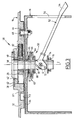
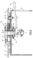
- the seat 10 also comprises means 28 for reversing the upper portion 14 from front to back and vice versa. These turning means 28 are illustrated in more detail in FIGS. 2 to 9.
- the turning means 28 comprise a pivot 30 connecting the upper portion 14 and the base 16 of the seat.
- the geometric axis Z of this pivot 30, substantially vertical, is connected to the base 16.
- the pivot 30 extends through two substantially horizontal walls vis-à-vis, one mobile 32 and the other 34 fixed.
- the first wall 32 upper, delimits a reinforcement of the upper part 14.
- the second wall 34 lower, delimits the base 16.
- the turning means 28 also comprise a slider 36 mounted to be displaceable in translation, substantially perpendicular to the Z axis, in a rectilinear guide rail 38 formed in the upper wall 32.
- the slider 36 forms a bearing rotatably mounted around the pivot 30. The rotation of the slider 36 is facilitated by a needle bearing 40 interposed between the pivot 30 and the slider 36 (see Figures 3 to 5).
- the pivot 30 extends through an oblong hole 42, elongated in a direction substantially parallel to that of the guide rail 38, formed in the movable upper wall 32.
- the pivot 30 also extends through a circular orifice 44, forming bearing, formed in the fixed lower wall 34.
- the turning means 28 further comprise two complementary cams carried respectively by the base 16 and the upper part 14.
- a first cam forms a finger 46, substantially vertical, integral with the bottom wall 34.
- the second cam is delimited by a groove 48 forming a guide formed in the upper wall 32.
- This groove 48 extends substantially parallel to a plane perpendicular to the Z axis.
- the profile of the groove 48 evolves so as to impose the movable upper portion 14 a predetermined reversal path.
- the groove 48 comprises two rectilinear end sections forming ramps 48A, 48B and an intermediate curvilinear section 48C.
- the ramps 48A, 48B are inclined with respect to the translational movement direction of the slide 36, so that these ramps cooperate with the finger 46 so as to impose on the upper part 14 displacements resulting from a combination of a movement rotation about the Z axis and a translational movement substantially perpendicular to this axis Z.
- the curvilinear portion 48C cooperates with the finger 46 so as to impose on the upper portion 14 a displacement in rotation about the Z axis.
- the seat 10 comprises means 50 for locking the upper part 14 relative to the base 16. These locking means 50 are controlled so as to be locked or released by a lever 52 provided with an operating end 54 extending from the inside to the outside of the base 16 through an opening 56 of the latter.
- the locking means 50 comprise means for clamping two friction faces F1, F2 delimiting, respectively, the movable top wall 32 and the fixed bottom wall 34. These friction faces F1, F2 extend substantially perpendicular to the Z axis.
- the clamping means carried by the pivot 30, comprise an end head of this pivot, forming a fixed jaw 58, and a movable jaw 60 mounted to slide axially on the pivot 30.
- the movable upper wall 32 and the fixed lower wall 34 extend between the fixed jaws 58 and mobile 60.
- An anti-friction pad, carried by the movable upper wall 32 is in contact with the fixed jaw 58 to minimize friction between the fixed jaw 58 and the movable upper wall 32 when the latter moves perpendicularly to the Z axis.
- the movable jaw 60 elastically deformable in the direction of the Z axis, is movable between a decompressed position for separating the friction faces F1, F2, as shown in FIGS. 3 and 4, and a compressed clamping position of these friction faces F1, F2, as shown in FIG.
- the decompressed and compressed positions of the movable jaw 60 correspond, respectively, to the unlocking and locking positions of the means 50.
- the movable jaw 60 comprises, for example, two spring washers 64,66 interposed between two flat washers 68,70.
- the spring washers 64, 66 are for example of the Belleville type.
- the movable jaw 60 is displaceable and axially compressible by cooperation with a cam 72 articulated on the pivot 30, possibly with a play in the direction of the Z axis, around a geometric axis X substantially perpendicular to this axis Z.
- cam 72 preferably forms an articulated end of the control lever 52 opposite its operating end 54.
- cam 72 is supported on a plane washer 74 immobilized axially by a stop nut 76 screwed onto the end of the pivot 30 opposite to the fixed jaw 58.
- the friction face F1 carried by the movable upper wall 32 comprises rolling members shown in particular in FIG. 4.
- these members for example as many as three, each comprise a ball 78.
- Each ball 78 is displaceable substantially parallel to the Z axis between a projecting position for bracing the friction faces F1, F2, in which the ball 78 is in rolling contact with the friction face F2 the base (see Figure 4), and a retracted position in which the friction faces F1, F2 are in contact with each other so as to immobilize the upper portion 14 of the seat relative to the base 16.
- the balls 78 are biased resiliently in the projecting position by springs 80 urging the rolling members.
- the upper portion 14 of the seat is in a first normal position of use of this seat as shown in Figure 6.
- the locking means 50 are activated (control lever 52 in the up position) so as to immobilize the part upper 14 relative to the base 16.
- control lever 52 preferably with the foot
- mobile upper part 14 can then move relative to the base 16.
- the cam finger 46 then cooperates with the ramp 48A, which has the effect of imposing on the upper part 14 a combined translational movement, tending to move the upper part 14 away from the neighboring side wall 26 in a direction transverse to the Z axis, and rotation about this Z axis (see Figure 7).
- the displacement in translation of the upper portion 14 results from the displacement of the slide 36 in its guide rail 38.
- the displacement of this slide 36 is preferably assisted by a compression spring 82 (see in particular Figure 3) interposed between the ends vis-à-vis this slider and the rail 38.
- the rotational displacement of the upper portion 14 results from the rotation of the slider 36 around the pivot 30.
- the cam follower 46 then cooperates with the curvilinear portion 48C which has the effect of rotating the movable portion 14 about the axis Z so as to bring this portion 14 in the position shown in FIG. 8. It will be noted that the positions of the movable upper portion 14 shown in Figures 7 and 8 are substantially symmetrical with respect to a transverse vertical plane of the vehicle.
- cam finger 46 cooperates with the second ramp 48B which has the effect of completing the overturning of the movable upper portion 14 and bringing this portion 14 with the adjacent side wall 26, as shown in Figure 9 .
- the operator moves the upper portion 14 in a path necessarily inverse to that described above.
- the electrical means for example drive means for driving the upper part 14
- the electrical cables extending, if necessary, between this part 14 and this base. 16 are not likely to wind up accidentally around the pivot 30 as a result of successive rotations of the upper part 14 always in the same direction.
- the control could be local (for example a push-button control by seat), or centralized for all or part of the seats of a vehicle.
Landscapes
- Engineering & Computer Science (AREA)
- Mechanical Engineering (AREA)
- Seats For Vehicles (AREA)
- Chairs Characterized By Structure (AREA)
Claims (10)
- Sitz des Typs, der einen beweglichen oberen Teil (14), der wenigstens einen Insassen aufnimmt und von einem ein Fußgestell (16) bildenden festen unteren Teil getragen wird, und Mittel (28) zum Schwenken des oberen Teils (14) von vorn nach hinten und umgekehrt umfasst,
wobei die Schwenkmittel (28) umfassen:- einen Drehzapfen (30), der den oberen Teil (14) und das Fußgestell (16) verbindet, wobei die Achse (Z) dieses Drehzapfens (30) im Wesentlichen vertikal ist und mit dem Fußgestell (16) verbunden ist, und- zwei komplementäre Nocken (46, 48), die von dem Fußgestell (16) bzw. von dem oberen Teil (14) getragen werden und wovon einer ein Verlaufsprofil aufweist, das für den oberen Teil (14) eine vorgegebene Schwenkbahn erzwingt,
dadurch gekennzeichnet, dass die Schwenkmittel ein Gleitelement (36) umfassen, das ein Lager bildet, das am oberen Teil (14) rotatorisch um den Drehzapfen (30) und translatorisch im Wesentlichen senkrecht zur Achse (Z) dieses Drehzapfens (30) in Bezug auf den oberen Teil (14) verlagerbar angebracht ist, wobei die Achse des Drehzapfens (Z) mit dem Gleitelement (36) verbunden ist. - Sitz nach Anspruch 1, dadurch gekennzeichnet, dass ein erster Nocken einen mit dem Fußgestell (16) verbundenen Zapfen (46) bildet und der zweite Nocken eine Führung (48) mit einem im oberen Teil (14) ausgebildeten Verlaufsprofil bildet, wobei diese Führung (48) zu einer zur Achse (Z) des Drehzapfens (30) senkrechten Ebene im Wesentlichen parallel verläuft.
- Sitz nach Anspruch 2, dadurch gekennzeichnet, dass die Führung (48) umfasst:zwei geradlinige End-Teilstücke, die Rampen (48A, 48B) bilden, die für den oberen Teil (14) Verlagerungen erzwingen, die sich aus einer Kombination einer Drehbewegung um die Achse (Z) des Drehzapfens und einer translatorischen Bewegung im Wesentlichen senkrecht zu dieser Achse (Z) des Drehzapfens ergeben, undein gekrümmtes Zwischen-Teilstück (48C), das für den oberen Teil (14) eine rotatorische Verlagerung um die Achse (Z) des Drehzapfens erzwingt.
- Sitz nach einem der vorhergehenden Ansprüche, dadurch gekennzeichnet, dass er freigebbare Mittel (50) zum Verriegeln des oberen Teils (14) in Bezug auf das Fußgestell (16) umfasst.
- Sitz nach Anspruch 4, dadurch gekennzeichnet, dass die Verriegelungsmittel (50) Mittel (58, 60) umfassen, um zwei Reibflächen (F1, F2), die den oberen Teil (14) bzw. das Fußgestell (16) begrenzen, in einander zugewandter Stellung im Wesentlichen senkrecht zur Achse (C) des Drehzapfens festzuklemmen, wobei diese Klemmmittel von dem Drehzapfen getragen werden.
- Sitz nach Anspruch 5, dadurch gekennzeichnet, dass sich der Drehzapfen (30) durch einander zugewandte Wände (32, 34) des oberen Teils (14) bzw. des Fußgestells (16), die die Reibflächen (F1, F2) tragen, erstreckt und dass die Klemmmittel einen Endkopf des Drehzapfens (30), der eine feste Klemmbacke (58) bildet, und eine am Drehzapfen (30) axial gleitend angebrachte bewegliche Klemmbacke (60) umfassen, wobei sich die einander zugewandten Wände (32, 34) zwischen der festen Klemmbacke (58) und der beweglichen Klemmbacke (60) erstrecken, wobei die bewegliche Klemmbacke (60) axial elastisch verformbar und zwischen einer nicht komprimierten getrennten Position der Reibflächen (F1, F2) und einer komprimierten Klemmposition dieser Reibflächen (F1, F2) verlagerbar ist.
- Sitz nach Anspruch 6, dadurch gekennzeichnet, dass die bewegliche Klemmbacke (60) durch Zusammenwirken mit einem Nocken (72), der am Drehzapfen (30) um eine zu jener des Drehzapfens (30) im Wesentlichen senkrechte Achse (X) angelenkt ist, axial verlagerbar und komprimierbar ist.
- Sitz nach Anspruch 7, dadurch gekennzeichnet, dass der Nocken (72) das Ende eines Steuerhebels (52) der Verriegelungsmittel (50) bildet.
- Sitz nach einem der Ansprüche 5 bis 8, dadurch gekennzeichnet, dass die Reibfläche (F1) des oberen Teils (14) Wälzorgane, vorzugsweise Kugeln (78), umfasst, die im Wesentlichen parallel zur Achse (Z) des Drehzapfens zwischen einer vorstehenden Abstandshalteposition der einander zugewandten Reibflächen (F1, F2), in der diese Organe mit der Reibfläche (F2) des Fußgestells (16) in einem Wälzkontakt sind, und einer eingezogenen Kontaktposition der einander zugewandten Reibflächen (F1, F2) verlagerbar sind, wobei die Wälzorgane in die vorstehende Position elastisch zurückgestellt werden.
- Schienenfahrzeug, dadurch gekennzeichnet, dass es einen Sitz nach einem der vorhergehenden Ansprüche enthält.
Applications Claiming Priority (2)
| Application Number | Priority Date | Filing Date | Title |
|---|---|---|---|
| FR9814291A FR2785862B1 (fr) | 1998-11-13 | 1998-11-13 | Siege tournant, notamment pour vehicule ferroviaire |
| FR9814291 | 1998-11-13 |
Publications (2)
| Publication Number | Publication Date |
|---|---|
| EP1000832A1 EP1000832A1 (de) | 2000-05-17 |
| EP1000832B1 true EP1000832B1 (de) | 2006-02-01 |
Family
ID=9532708
Family Applications (1)
| Application Number | Title | Priority Date | Filing Date |
|---|---|---|---|
| EP99402650A Expired - Lifetime EP1000832B1 (de) | 1998-11-13 | 1999-10-25 | Drehbarer Sitz, insbesondere für ein Schienenfahrzeug |
Country Status (7)
| Country | Link |
|---|---|
| US (1) | US6302483B1 (de) |
| EP (1) | EP1000832B1 (de) |
| JP (1) | JP3472515B2 (de) |
| CA (1) | CA2289718C (de) |
| DE (1) | DE69929668T2 (de) |
| ES (1) | ES2258317T3 (de) |
| FR (1) | FR2785862B1 (de) |
Families Citing this family (25)
| Publication number | Priority date | Publication date | Assignee | Title |
|---|---|---|---|---|
| US6513872B2 (en) * | 2001-05-18 | 2003-02-04 | De Sede Ag | Multipart upholstered furniture |
| US6991060B2 (en) * | 2001-12-13 | 2006-01-31 | General Motors Corporation | Vehicle having a movable driving position |
| US6814174B2 (en) * | 2003-01-23 | 2004-11-09 | Ingersoll-Rand Company | Telescoping seat assembly for a construction vehicle |
| US7520567B2 (en) | 2004-09-23 | 2009-04-21 | Crown Equipment Corporation | Systems and methods for seat repositioning |
| US7059680B2 (en) * | 2004-09-23 | 2006-06-13 | Crown Equipment Corporation | Seat repositioning device with release on control handle |
| US7121608B2 (en) * | 2004-09-23 | 2006-10-17 | Crown Equipment Corporation | Rotating and/or swiveling seat |
| US7364234B2 (en) * | 2005-08-25 | 2008-04-29 | Brunswick Corporation | Eccentric swivel mechanism for a vehicle seat |
| JP4770561B2 (ja) * | 2006-04-13 | 2011-09-14 | 株式会社豊田自動織機 | 車両用シート転回装置 |
| DE102006052536A1 (de) * | 2006-11-06 | 2008-05-08 | Poggenpohl Möbelwerke GmbH | Bestuhlung einer Fahrzeugkabine |
| US8251456B2 (en) * | 2009-11-23 | 2012-08-28 | Kustom Seating Unlimited | Locking mechanism for rotating seats |
| US8398143B1 (en) * | 2010-04-19 | 2013-03-19 | Randal B Haley | Multi-configured double stroller apparatus and method of using same |
| US8449011B2 (en) | 2010-06-04 | 2013-05-28 | Ford Global Technologies, Llc | Monopod seat structure for automotive seats and method |
| DE202012003697U1 (de) * | 2012-04-12 | 2013-07-15 | Joseph Vögele AG | Straßenfertiger sowie Sitzkonsole |
| CN103417019A (zh) * | 2012-05-25 | 2013-12-04 | 上海同耀汽车配件有限公司 | 旋转机构 |
| DE102013227013B4 (de) * | 2013-12-20 | 2022-09-29 | Volkswagen Aktiengesellschaft | Sitzvorrichtung, Fahrgastraum, Fahrzeug |
| JP6753720B2 (ja) * | 2016-07-28 | 2020-09-09 | コイト電工株式会社 | 座席支持機構 |
| USD865501S1 (en) * | 2016-12-02 | 2019-11-05 | Mobb Health Care Ltd Corporation Canada | Swivel chair bearing |
| DE102017131057A1 (de) * | 2017-12-22 | 2019-06-27 | Airbus Operations Gmbh | Sitzgruppe für ein Passagierflugzeug |
| US10967761B2 (en) * | 2019-04-30 | 2021-04-06 | Honda Motor Co., Ltd. | Pod seat with rotation |
| JP6932469B2 (ja) * | 2019-12-27 | 2021-09-08 | コイト電工株式会社 | 座席装置 |
| JP7062709B2 (ja) * | 2020-02-28 | 2022-05-06 | コイト電工株式会社 | 座席装置 |
| JP7062710B2 (ja) * | 2020-02-28 | 2022-05-06 | コイト電工株式会社 | 座席装置 |
| USD972875S1 (en) | 2020-10-09 | 2022-12-20 | Mobb Health Care Ltd Corporation | Unitary swivel |
| US11596279B2 (en) | 2021-03-30 | 2023-03-07 | Mobb Health Care Ltd Corporation | Swivel commode chair |
| USD974815S1 (en) | 2021-11-02 | 2023-01-10 | Mobb Health Care Ltd Corporation | Unitary swivel |
Family Cites Families (12)
| Publication number | Priority date | Publication date | Assignee | Title |
|---|---|---|---|---|
| US1735321A (en) * | 1926-07-02 | 1929-11-12 | John B Kilburn | Car seat |
| US1741784A (en) * | 1927-02-23 | 1929-12-31 | Milwaukee Electric Railway & L | Car-seat-reversing mechanism |
| US2247264A (en) * | 1938-02-21 | 1941-06-24 | Karpen & Bros S | Revolving car seat |
| US3066979A (en) * | 1959-08-14 | 1962-12-04 | Rockwell Standard Co | Swivel seat constructions |
| US3394964A (en) * | 1966-11-01 | 1968-07-30 | American Seating Co | Revolving transportation seat |
| US4417715A (en) * | 1981-03-05 | 1983-11-29 | National Seating Co. | Reversible transportation seat |
| US4824170A (en) * | 1984-04-06 | 1989-04-25 | Steven Goldmeier | Outdoor swivel chair |
| US4822099A (en) * | 1987-03-31 | 1989-04-18 | Fujikiko Kabushiki Kaisha | Rotary seat |
| US5046782A (en) * | 1990-05-29 | 1991-09-10 | Lundeen Jack M | Rotatable sun chair |
| US5636884A (en) * | 1995-03-15 | 1997-06-10 | Lear Seating Corporation | Pivotal seat and support |
| US5634537A (en) * | 1995-04-19 | 1997-06-03 | Lord Corporation | Locking and positioning device |
| US6027170A (en) * | 1999-02-19 | 2000-02-22 | Paccar Inc | Rotating vehicle seat |
-
1998
- 1998-11-13 FR FR9814291A patent/FR2785862B1/fr not_active Expired - Fee Related
-
1999
- 1999-10-25 EP EP99402650A patent/EP1000832B1/de not_active Expired - Lifetime
- 1999-10-25 DE DE69929668T patent/DE69929668T2/de not_active Expired - Fee Related
- 1999-10-25 ES ES99402650T patent/ES2258317T3/es not_active Expired - Lifetime
- 1999-11-05 CA CA002289718A patent/CA2289718C/fr not_active Expired - Fee Related
- 1999-11-11 JP JP32063799A patent/JP3472515B2/ja not_active Expired - Fee Related
- 1999-11-12 US US09/439,080 patent/US6302483B1/en not_active Expired - Fee Related
Also Published As
| Publication number | Publication date |
|---|---|
| JP3472515B2 (ja) | 2003-12-02 |
| DE69929668D1 (de) | 2006-04-13 |
| JP2000190844A (ja) | 2000-07-11 |
| FR2785862B1 (fr) | 2003-05-16 |
| DE69929668T2 (de) | 2006-10-26 |
| CA2289718A1 (fr) | 2000-05-13 |
| US6302483B1 (en) | 2001-10-16 |
| EP1000832A1 (de) | 2000-05-17 |
| FR2785862A1 (fr) | 2000-05-19 |
| ES2258317T3 (es) | 2006-08-16 |
| CA2289718C (fr) | 2003-09-30 |
Similar Documents
| Publication | Publication Date | Title |
|---|---|---|
| EP1000832B1 (de) | Drehbarer Sitz, insbesondere für ein Schienenfahrzeug | |
| EP0265317A1 (de) | Vorrichtung zur Schnellverstellung und Blockierung eines linear bewegten Teiles, insbesondere anwendbar für die Tischführung an Holzbearbeitungsmaschinen | |
| FR2486787A1 (fr) | Mecanisme de support d'une structure de siege pouvant pivoter | |
| FR2743764A1 (fr) | Mecanisme d'articulation pour siege de vehicule, et siege comportant un tel mecanisme | |
| FR2580759A1 (fr) | Dispositif de commande du deplacement d'un element, notamment d'un siege ou des parties d'un siege d'un vehicule automobile, par rapport a un bati | |
| EP0265316A1 (de) | Verriegelungssystem für eine lineare Schnellverstell- und Blockiereinrichtung eines beweglichen Teiles gegenüber einem festen Teil | |
| FR2963586A1 (fr) | Glissiere pour siege de vehicule automobile a verrouillage lateral sans jeu | |
| EP1000831B1 (de) | Drehbarer Sitz mit verbesserter Bewegung, insbesondere für ein Schienenfahrzeug | |
| FR2524285A1 (fr) | Siege transformable, notamment de vehicule automobile | |
| EP1424278B1 (de) | Flugzeugcockpitfenster | |
| EP1597104A2 (de) | Verriegelung eines versenkbaren fahrzeugdachs | |
| EP0479659B1 (de) | Scheibenwischerarm besonders für Kraftfahrzeuge | |
| FR2786520A1 (fr) | Verrou et agencement de ce verrou dans un support | |
| EP0305245A1 (de) | Verriegelung eines Deckels auf einem Rahmen | |
| EP0433103B1 (de) | Elektrische Steuervorrichtung für einen schwenkbaren, an zwei Endpunkten seiner Bewegung frei gehaltenen Hebel und Schloss mit dieser Vorrichtung | |
| EP1751403B1 (de) | Ventiltriebvorrichtung | |
| EP1747935B1 (de) | Gleitanordnung und Möbelstück mit Gleitanordnung für Fahrzeuginnenraum | |
| FR2596096A1 (fr) | Dispositif d'entrainement d'une tige de commande d'actionneur de serrure notamment de serrure de porte de vehicule automobile, et serrure equipee d'un tel dispositif | |
| EP0252800A1 (de) | Schalter, insbesondere für die Steuerung von Wisch-Wasch-Kombinationen von Kraftfahrzeugen | |
| FR2792964A1 (fr) | Serrure manoeuvrable electriquement ou mecaniquement | |
| WO2017046527A1 (fr) | Dispositif de verrouillage bi-positions d'un dossier de siege arriere de vehicule automobile | |
| WO2013014377A1 (fr) | Dispositif de verrouillage en position parc d'une boite de vitesses automatique pour vehicule automobile | |
| FR2791082A1 (fr) | Dispositif de verrouillage d'un organe sur un support | |
| EP0063081B1 (de) | Montagevorrichtung für einen verstellbaren Fahrzeugsitz | |
| FR2829433A1 (fr) | Ensemble de liaison liberable d'un premier organe de structure amovible sur un second organe de structure, et vehicule automobile le comportant |
Legal Events
| Date | Code | Title | Description |
|---|---|---|---|
| PUAI | Public reference made under article 153(3) epc to a published international application that has entered the european phase |
Free format text: ORIGINAL CODE: 0009012 |
|
| AK | Designated contracting states |
Kind code of ref document: A1 Designated state(s): BE DE ES GB IT |
|
| AX | Request for extension of the european patent |
Free format text: AL;LT;LV;MK;RO;SI |
|
| 17P | Request for examination filed |
Effective date: 20000831 |
|
| AKX | Designation fees paid |
Free format text: BE DE ES GB IT |
|
| 17Q | First examination report despatched |
Effective date: 20030710 |
|
| GRAP | Despatch of communication of intention to grant a patent |
Free format text: ORIGINAL CODE: EPIDOSNIGR1 |
|
| GRAS | Grant fee paid |
Free format text: ORIGINAL CODE: EPIDOSNIGR3 |
|
| GRAA | (expected) grant |
Free format text: ORIGINAL CODE: 0009210 |
|
| RAP1 | Party data changed (applicant data changed or rights of an application transferred) |
Owner name: ALSTOM HOLDINGS |
|
| AK | Designated contracting states |
Kind code of ref document: B1 Designated state(s): BE DE ES GB IT |
|
| PG25 | Lapsed in a contracting state [announced via postgrant information from national office to epo] |
Ref country code: IT Free format text: LAPSE BECAUSE OF FAILURE TO SUBMIT A TRANSLATION OF THE DESCRIPTION OR TO PAY THE FEE WITHIN THE PRESCRIBED TIME-LIMIT;WARNING: LAPSES OF ITALIAN PATENTS WITH EFFECTIVE DATE BEFORE 2007 MAY HAVE OCCURRED AT ANY TIME BEFORE 2007. THE CORRECT EFFECTIVE DATE MAY BE DIFFERENT FROM THE ONE RECORDED. Effective date: 20060201 |
|
| REG | Reference to a national code |
Ref country code: GB Ref legal event code: FG4D Free format text: NOT ENGLISH |
|
| REF | Corresponds to: |
Ref document number: 69929668 Country of ref document: DE Date of ref document: 20060413 Kind code of ref document: P |
|
| GBT | Gb: translation of ep patent filed (gb section 77(6)(a)/1977) |
Effective date: 20060512 |
|
| REG | Reference to a national code |
Ref country code: ES Ref legal event code: FG2A Ref document number: 2258317 Country of ref document: ES Kind code of ref document: T3 |
|
| PLBE | No opposition filed within time limit |
Free format text: ORIGINAL CODE: 0009261 |
|
| STAA | Information on the status of an ep patent application or granted ep patent |
Free format text: STATUS: NO OPPOSITION FILED WITHIN TIME LIMIT |
|
| 26N | No opposition filed |
Effective date: 20061103 |
|
| PGFP | Annual fee paid to national office [announced via postgrant information from national office to epo] |
Ref country code: ES Payment date: 20071030 Year of fee payment: 9 Ref country code: DE Payment date: 20071025 Year of fee payment: 9 |
|
| PGFP | Annual fee paid to national office [announced via postgrant information from national office to epo] |
Ref country code: IT Payment date: 20071024 Year of fee payment: 9 |
|
| PGFP | Annual fee paid to national office [announced via postgrant information from national office to epo] |
Ref country code: BE Payment date: 20071123 Year of fee payment: 9 |
|
| PGFP | Annual fee paid to national office [announced via postgrant information from national office to epo] |
Ref country code: GB Payment date: 20071023 Year of fee payment: 9 |
|
| BERE | Be: lapsed |
Owner name: ALSTOM HOLDINGS Effective date: 20081031 |
|
| GBPC | Gb: european patent ceased through non-payment of renewal fee |
Effective date: 20081025 |
|
| PG25 | Lapsed in a contracting state [announced via postgrant information from national office to epo] |
Ref country code: IT Free format text: LAPSE BECAUSE OF NON-PAYMENT OF DUE FEES Effective date: 20081025 Ref country code: DE Free format text: LAPSE BECAUSE OF NON-PAYMENT OF DUE FEES Effective date: 20090501 |
|
| PG25 | Lapsed in a contracting state [announced via postgrant information from national office to epo] |
Ref country code: BE Free format text: LAPSE BECAUSE OF NON-PAYMENT OF DUE FEES Effective date: 20081031 |
|
| PG25 | Lapsed in a contracting state [announced via postgrant information from national office to epo] |
Ref country code: GB Free format text: LAPSE BECAUSE OF NON-PAYMENT OF DUE FEES Effective date: 20081025 |
|
| REG | Reference to a national code |
Ref country code: ES Ref legal event code: FD2A Effective date: 20081027 |
|
| PG25 | Lapsed in a contracting state [announced via postgrant information from national office to epo] |
Ref country code: ES Free format text: LAPSE BECAUSE OF NON-PAYMENT OF DUE FEES Effective date: 20081027 |