EP1000853A1 - Moteur du type hors-bord a propulsion par jet d'eau - Google Patents
Moteur du type hors-bord a propulsion par jet d'eau Download PDFInfo
- Publication number
- EP1000853A1 EP1000853A1 EP98945564A EP98945564A EP1000853A1 EP 1000853 A1 EP1000853 A1 EP 1000853A1 EP 98945564 A EP98945564 A EP 98945564A EP 98945564 A EP98945564 A EP 98945564A EP 1000853 A1 EP1000853 A1 EP 1000853A1
- Authority
- EP
- European Patent Office
- Prior art keywords
- outboard motor
- shaft
- screen
- transverse
- ship body
- Prior art date
- Legal status (The legal status is an assumption and is not a legal conclusion. Google has not performed a legal analysis and makes no representation as to the accuracy of the status listed.)
- Withdrawn
Links
Images



Classifications
-
- B—PERFORMING OPERATIONS; TRANSPORTING
- B63—SHIPS OR OTHER WATERBORNE VESSELS; RELATED EQUIPMENT
- B63H—MARINE PROPULSION OR STEERING
- B63H20/00—Outboard propulsion units, e.g. outboard motors or Z-drives; Arrangements thereof on vessels
-
- B—PERFORMING OPERATIONS; TRANSPORTING
- B63—SHIPS OR OTHER WATERBORNE VESSELS; RELATED EQUIPMENT
- B63H—MARINE PROPULSION OR STEERING
- B63H11/00—Marine propulsion by water jets
- B63H11/01—Marine propulsion by water jets having means to prevent foreign material from clogging fluid passage way
-
- B—PERFORMING OPERATIONS; TRANSPORTING
- B63—SHIPS OR OTHER WATERBORNE VESSELS; RELATED EQUIPMENT
- B63H—MARINE PROPULSION OR STEERING
- B63H11/00—Marine propulsion by water jets
- B63H11/02—Marine propulsion by water jets the propulsive medium being ambient water
- B63H11/04—Marine propulsion by water jets the propulsive medium being ambient water by means of pumps
- B63H11/08—Marine propulsion by water jets the propulsive medium being ambient water by means of pumps of rotary type
-
- B—PERFORMING OPERATIONS; TRANSPORTING
- B63—SHIPS OR OTHER WATERBORNE VESSELS; RELATED EQUIPMENT
- B63H—MARINE PROPULSION OR STEERING
- B63H11/00—Marine propulsion by water jets
- B63H11/02—Marine propulsion by water jets the propulsive medium being ambient water
- B63H11/10—Marine propulsion by water jets the propulsive medium being ambient water having means for deflecting jet or influencing cross-section thereof
- B63H11/107—Direction control of propulsive fluid
- B63H11/11—Direction control of propulsive fluid with bucket or clamshell-type reversing means
-
- B—PERFORMING OPERATIONS; TRANSPORTING
- B63—SHIPS OR OTHER WATERBORNE VESSELS; RELATED EQUIPMENT
- B63H—MARINE PROPULSION OR STEERING
- B63H11/00—Marine propulsion by water jets
- B63H11/02—Marine propulsion by water jets the propulsive medium being ambient water
- B63H11/10—Marine propulsion by water jets the propulsive medium being ambient water having means for deflecting jet or influencing cross-section thereof
- B63H11/107—Direction control of propulsive fluid
- B63H11/113—Pivoted outlet
-
- B—PERFORMING OPERATIONS; TRANSPORTING
- B63—SHIPS OR OTHER WATERBORNE VESSELS; RELATED EQUIPMENT
- B63H—MARINE PROPULSION OR STEERING
- B63H11/00—Marine propulsion by water jets
- B63H11/02—Marine propulsion by water jets the propulsive medium being ambient water
- B63H11/04—Marine propulsion by water jets the propulsive medium being ambient water by means of pumps
- B63H11/08—Marine propulsion by water jets the propulsive medium being ambient water by means of pumps of rotary type
- B63H2011/081—Marine propulsion by water jets the propulsive medium being ambient water by means of pumps of rotary type with axial flow, i.e. the axis of rotation being parallel to the flow direction
Definitions
- the present invention relates to improvement in a water jet propelling type outboard motor.
- Japanese Utility Model Application Laid-Open No. 5-65795 also, there has been disclosed on example of a water jet propelling motor provided with forward and rearward movable screens before and ahead a water suction inlet.
- the screens prevent floating materials such as dusts from flowing in the motor from the water suction inlet. By opening the screens, the floating materials captured by the screens are removed due to water flow.
- the present invention has been attained in view of the drawbacks in the above-mentioned conventional arts, and an object thereof is to provide a compact water jet propelling type outboard motor having an excellent straight advancing performance. Also, another object of the present invention is to provide a water jet propelling type outboard motor where floating materials which have been attached to the screens can be removed even while a ship is being travelling.
- a water jet propelling type outboard motor comprises: a casing housing having a front end lower opening, a rear end transverse opening, a first inside space extending from the lower opening obliquely and rearward, and a second inside space extending generally horizontally up to the transverse opening form a rear end of the first inside space; a frame extending upwardly to be mounted to a ship body, an motor mounted on the frame; a gear case disposed transversely ahead of the second inside space and generally vertically above the lower opening; a driving vertical shaft extending downwardly from the motor to be inserted in the gear box; a following transverse shaft extending transversely and forwardly from the second inside space to be inserted in the gear case; a power transmission mechanism disposed the gear box and coupling the driving vertical shaft and the following transverse shaft; and an impeller rotated by the following transverse shaft and sucking and pressurizing water from the lower opening to jet the same from the transverse opening.
- the driving vertical shaft extending from the motor and the following transverse shaft for rotating the impeller are coupled to each other by the power transmission mechanism in the gear case, and the gear case is disposed transversely forward of the second inside space and generally vertically above the lower opening. Accordingly, the following transverse shaft can be shortened, and a projecting amount of the outboard motor extending from a ship body rearward can be reduced.
- the power transmission mechanism can be constituted with an upper bearing rotatably supporting the driving vertical shaft fixed to the gear case, an upper bevel gear fixed to a lower end of the driving vertical shaft, a transverse bearing rotatably supporting a front end of the transverse following shaft fixed to the gear case, and a transverse bevel gear meshing with the upper bevel gear fixed to the transverse following shaft.
- a second aspect of the present invention is an outboard motor according to the first aspect, further comprising a screen which be rotatably supported to a front edge of the lower opening and which moves between a closing position where the screen covers the lower opening and an open position where the screen has been shifted downwardly from the lower opening, a biasing member for biasing the screen towards the closing position, an operating shaft which is supported to the casing member rotatably in forward and rearward directions, a first engaging portion which moves together with the screen, and a second engaging portion which moves together with the operating shaft, wherein, when the operating shaft moves from a first position positioned forward to a second position positioned rearward, the first engaging portion is brought into engagement with the second engaging portion to move the screen from the closing position to the open position, and when the operation moves beyond the second position, the first engaging portion is released from the second engaging portion so that the screen is returned back to the closing position from the open position by the basing member.
- the first and second engaging portions can be disposed such that a moving region of the second engaging portion obtained when the operating shaft moves from the first position to the second position overlapping a moving region of the first engaging portion obtained when the screen moves from the closing position to the open position.
- the operating shaft is appropriately moved in an inclination manner from the first position in a traveling rearward direction.
- the second engaging portion is engaged with the first engaging portion, and the screen is moved so as to be opened from the closing position against a biasing force of the biasing member so that the lower opening is opened.
- the screen is opened from its rear.
- the first engaging portion is released from engagement with the second engaging portion and the screen instantaneously moves to the closing position by a biasing force of the biasing member.
- the screen opens the lower opening.
- the screen behaves such that, after it opens the lower opening slowly, it rapidly moves to the closing position.
- a structure may be achieved that a cable is connected to the operating shaft, the cable extends up to a steering seat and the operating shaft is operable from the steering seat via the cable.
- a third aspect of the present invention is an outboard motor according to the first or second aspect, wherein the impeller comprises a spiral blade having an outer peripheral edge portion close to a peripheral face of the second inside space and an outer distal end portion extending towards the first inside space.
- the spiral blade has the outer peripheral distal portion extending towards the first inside space, a suction portion of the impeller can be formed widely. Therefore, the floating materials which have passed through the screen are hard to stick to the impeller and they are easily exhausted together with pressurized water from the transverse opening.
- a fourth aspect of the present invention is an outboard motor according to the first or second aspect, further comprising a front contacting wall which comes in contact with a lower end portion of a transom board of the ship body in a state where the frame has been mounted on the ship body, and a continuous face formed between a lower end of the front contacting wall and a forward peripheral edge of the lower opening.
- a closely contacting plate contacting with the transom board may be attached to an outer face of the front contacting wall.
- the lower opening may be positioned on almost the same plane as a rear bottom face of the ship body in a state where the frame has been mounted on the ship body.
- a fifth aspect of the present invention is an outboard motor according to the first or second aspect, wherein a rectifying plate having a flange shape is provided at a peripheral edge of the lower opening and the rectifying plate suppresses water flow coming from the rear bottom face of the ship from moving upwardly.
- the rectifying plate is useful for bringing the lower opening into close contact with water face, when the outboard motor is mounted on the ship body and the ship is caused to alight on water.
- a sixth aspect of the present invention is an outboard motor according to the first or second aspect, wherein the frame is mounted to be movable upward and downward relative to the ship body by a clamp with a female screw hole which is fixed to the ship body and a jack bolt engaged with the female screw hole in a threading manner and rotatably coupled to the frame.
- a vertical position of the outboard motor can be adjusted according to an attitude of the ship body. That is, water flow at the bottom of the ship flows smoothly during travelling so that the outboard motor can appropriately be set at a position where water can be sucked efficiently. Accordingly, occurrence of water flow resistance and occurrence of cavitation are prevented in a pump so that the ship can travel efficiently.
- forward means forward in a ship travelling direction
- rearward means rearward in the ship travelling direction
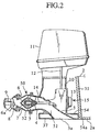
- a water jet propelling type outboard motor 1 is mounted on a stern of a ship 2.
- the outboard motor 1 comprises a casing member 50, an motor 11, a gear case 13, a vertical driving shaft (driving vertical shaft) 12, a horizontal following shaft (following transverse shaft) 14, a power transmission mechanism 15, and an impeller 5.
- the casing member 50 is constituted with a suction casing 3, a pump casing 4, and a discharge casing 6.
- a water suction inlet (lower opening) 3a is formed at one end of the suction casing 3 and the pump casing 4 is integrally provided at the other end thereof.
- a first inside space 51 extending obliquely upwardly and rearward from the suction inlet 3a is formed in the pump casing 4.
- One end of the discharge casing 6 is coupled to the pump casing 4 and the other end thereof is formed with a jetting outlet 6a.
- a second inside space 52 extending horizontally from the first inside space 51 to the jetting outlet 6a is formed inside both the casings 4, 6.
- the impeller 5 is provided inside the pump casing 4.
- a guiding blade 7 for rectifying spiral flow which has been pressurized by the impeller 5 in a linear flow is provided within the second inside space 52 rearward of the impeller 5.
- a deflector 8 for switching a travelling direction is formed outside of the jetting outlet 6a and a reverser 9 for backward propelling is formed outside of the deflector 8, respectively.
- a box-shaped frame 10 extending upwardly is provided on an upper portion of the suction casing 3.
- the motor 11 is mounted on an upper end of the frame 10.
- a front and upper end of the frame 10 is fixed to the stern of the ship body by a fixing member which is not shown.
- a box-shaped pedestal portion 54 opening downward is provided at a lower portion of the suction casing 3.
- a peripheral wall of the pedestal portion 54 surrounds a peripheral edge of the suction inlet 3a.
- a front wall (front contacting wall) 54a of the pedestal portion 54 comes in close surface contact with a lower portion of a transom board 31 of the ship body 2 in a state where the frame 10 has been fixed to the ship body 2, and a lower end of the front wall 54a reaches almost the same position as that of a rearward bottom face 2a of the ship body 2.
- a rectifying plate 37 with a flange shape is fixed between the peripheral wall of the pedestal portion 54 and a peripheral edge of the suction inlet 3a.
- the suction inlet 3a is positioned to be generally flush with the rearward bottom face 2a of the ship body 2, and a front portion outer face of the rectifying plate 37 forms a continuous face between a lower end of the front wall 54a and a forward peripheral edge of the suction inlet 3a.
- the gear case 13 is disposed laterally forward of the pump casing 4 and generally immediately above the suction inlet 3a.
- the gear case 13 is fixed to the suction casing 13.
- the vertical driving shaft 12 extends generally in a vertical downward direction to be inserted into the gear case 13.
- the horizontal following shaft 14 extends generally in a horizontal forward direction from inside of the pump casing 4 and projects from an inclining shoulder portion of the suction casing 3 to be inserted into the gear case 13.
- the impeller 5 is fixed coaxially to a rear end of the horizontal following shaft 14.
- the vertical driving shaft 12 and the horizontal following shaft 14 are coupled to each other via the power transmission mechanism 15. Thereby, driving force of the motor 11 is input in the impeller 5 through the vertical driving shaft 12, the power transmission mechanism 15 and the horizontal following shaft 14.
- the gear case 13 is fixed to an outer peripheral side wall of the suction casing 3 from which the horizontal following shaft 14 projects.
- the power transmission mechanism 15 is constituted with an upper bearing 16, an upper bevel gear 17, a transverse bearing 18, and a transverse bevel gear 19.
- the upper bearing 16 is fixed to an upper portion inside the gear case 13, and a lower portion of the vertical driving shaft 12 is rotatably supported by the upper bearing 16.
- the upper bevel gear 17 is fitted and fixed on a lower end of the vertical driving shaft 12.
- the transverse bearing 18 is fixed to a front portion of the gear case 13, and a front end of he horizontal following shaft 14 is rotatably supported by the transverse bearing 18.
- the transverse bevel gear 19 is fitted and fixed on a portion of the horizontal following shaft 14 in the vicinity of the front end thereof.
- the upper bevel gear 17 meshes with the transverse bevel gear 19.
- upper and transverse auxiliary bearings 55, 56 are respectively provided at an uppermost portion and a rear portion of the gear case 13.
- the impeller 5 has a hub 58 coaxially fixed to a rear end of the horizontal following shaft 14 and a plurality of spiral blades 59 projecting from the hub 58.
- a proximal end portions of the blades 59 are phase-shifted to one another along a peripheral direction to be mounted on the hub 58.
- An outer peripheral edge portions 59a of the blades 59 are positioned in the vicinity of an inner peripheral face of the pump casing 4 in order to improve the volume efficiency and the balance efficiency of the impeller 5.
- a forward (water flowing-in side) outer peripheral distal end portions 59b of the blades 59 extend in a direction (forward) of the suction casing 3. Thereby, a wide suction inlet is formed.
- the vertical driving shaft 12 extending from the motor 11 and the horizontal following shaft 14 for rotating the impeller 5 are coupled to each other by the power transmission mechanism 15 in the gear case 13, and the gear case 13 is disposed laterally forward of the second inside space 52 and generally immediately above the suction inlet 3a. Therefore, the horizontal following shaft 14 can be shortened and a projecting amount of the outboard motor 1 rearward of the ship body 2 can be reduced.
- the suction inlet 3a is positioned on almost the same plane as the rearward bottom face 2a of the ship body 2, and a continuous face is formed between the lower end of the front wall 54a and the forward peripheral edge of the suction inlet 3a by the front portion outer face of the rectifying plate 37. Thereby, water flow at the ship bottom flows further smoothly below the lower opening. Furthermore, water flow during travelling is hard to strike on a lower portion side face of the outboard motor 1 and water flow below the suction inlet 3a is further rectified by the rectifying plate 37.
- the rectifying plate 37 is useful to bring the suction inlet 3a into close contact with water surface when the outboard motor 1 is mounted on the ship body 2 and the ship body 2 is caused to alight on water.
- a suction portion of the impeller 5 can be formed widely. Accordingly, floating materials which have flowed in from the suction inlet 3a have been hard to stick to the impeller 5 and they can easily be exhausted from the jetting outlet 6a together with pressurized water.
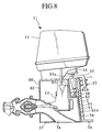
- a screen 21 for preventing floating materials from flowing in the suction inlet 3a is provided.
- the screen 21 is movable from a position (closed position) where the suction inlet 3a has been closed to a position (open position) where it has been opened.
- the pedestal portion 54 (refer to Fig. 2) is not provided, but a lower end of a peripheral wall (only a front wall 61 and a rear wall 62 are shown) of a frame 60 extends up to almost the same position as that of the suction inlet 3a.
- a lower portion (front contacting wall) 61a of a front wall 61 of the frame 60 is put in close contact with the transom board 31.
- the screen 21 is provided at the suction inlet 3a of the suction casing 3.
- a supporting plate 24 is fixed to the lower portion 61a of the front wall 61, and a rotating shaft 22 is rotatably supported to the supporting plate 24.
- a front edge portion of the screen 21 and a proximal portion of the operating shaft 23 are fixed to an outer periphery of the rotating shaft 22, and when the operating shaft is swung in front and rear directions, the suction inlet 3a of the suction casing 3 is opened and closed.
- a spring (biasing member) 25 is provided between the operating shaft 23 and the supporting plate 35. The operating shaft 23 is always pulled towards a ship body side, so that the screen 21 is biased to the closed position covering the suction inlet 3a.
- a rotating shaft 27 is rotatably supported a lower end outer side wall of the suction casing 3.
- a proximal portion of the operating shaft 26 is fixed to a periphery of the rotating shaft 27 and it is swingable in front and rear directions of the ship body 2.
- a central portion of an L-shaped hook 28 is rotatably supported to an intermediate portion of the operating shaft 26.
- An auxiliary spring 29 is provided between a front end portion 28a of the hook 28 and the operating shaft 26. The hook 28 is biased so as to be maintained at an almost constant intersecting angle to the operating shaft 26 by the spring 29.
- a push-pull cable 38 is coupled to an upper portion of the operating shaft 26 and the push-pull cable 38 extends up to a steering seat.
- a protrusion 30 (first engaging portion) projecting in a direction intersecting a moving direction of the operating shaft 23 is provided at an upper end of the operating shaft 23.
- An moving region of a rear end face (second engaging portion) 28b according to swing of the operating shaft 26 and a moving region of a the protrusion 30 according to swing of the operating shaft 23 overlaps each other sufficiently when the screen 21 has been put in the closed position, and they are gradually shifted to reduce their overlapping portion.
- the protrusion 30 is completely released downward from the moving region of the rear end face 28 of the hook 28.
- the protrusion 30 enters in a lower side of the hook 28, the operating shaft 26 is instantaneously returned back to a stern side by the spring 25, and the screen 21 is returned to the closed position instantaneously. Thereafter, when the operating shaft 26 pulled back to the first position which is forward, a portion of the rear end face 28b side of the hook 28 rides beyond the protrusion 30, and the hook 28 returns back to an initial state by the resilient force of the spring 29.
- the screen 21 intermittently opens/closes the suction inlet 3a.
- a opening/closing speed of the screen 21 an opening speed is slow, while a closing speed is rapid.
- the operating shaft 26 is moved appropriately in an inclining manner, rearward.
- the screen 21 is closed after the suction inlet 3a is opened.
- the screen 21 behaves such that the screen 21 moves to the closed position rapidly, after the suction inlet 3a is opened slowly.
- floating materials such as dirt or the like, which have been stuck to the screen 21 are securely pushed to be flow out by water flow so that the screen 21 is cleaned.
- floating materials are hard to flow into the suction inlet 3a during opening movement of the screen 21.
- the opening/closing operation of the screen 21 can easily be performed.
- An outboard motor 71 of this embodiment is mounted to the ship body 2 so as to be moved in upward and downward directions.
- the front wall 61 of the frame 60 is provided with a lower portion 61a, an upper portion 61c positioned rearward from the lower portion 61a, and a generally horizontal stepped portion 61b formed in a bent manner between the lower portion 61a and the upper portion 61c.
- a close contacting plate 36 made of rubber is attached on an outer face of the lower portion 61a of the front wall 61. The close contacting plate 36 comes in close surface-contact with an outer face of the transom board 31 of the ship body 2.
- a clamp 32 is fixed to an upper end portion of the transom board 31 by mounting screws 33.
- a female screw hole 32a is formed at a portion of the clamp 32 extending towards the stern, and a jack bolt 34 engaged with the female screw hole 32a in a threading manner extends downwardly.
- a lower end of the jack bolt 34 is coupled to a bearing 63 fixed on the stepped portion 61b of the front wall 61 of the frame 60.
- An upper end of the jack bolt 34 is fixed with a handle 35. The jack bolt 34 is moved upward and downward as a whole by rotating the handle 53 so that the outboard motor 71 suspended is moved upward and downward relative to the ship body 2.
- a vertical position of the outboard motor 71 can be adjusted according to the attitude of the ship body 2. That is, the outboard motor 71 can properly be set at a position where water flow at the ship bottom flows smoothly and water suction can be effected efficiently. Accordingly, occurrence of water flow resistance or occurrence of cavitation are prevented in the pump, so that the ship can travel efficiently.
- the impeller 5 with the spiral blades 59 is used, but instead thereof a screw propeller can be used in this invention.
- a following transverse shaft can be shorted, and an amount of an outboard motor projecting rearward of a ship body can be reduced.
- the present invention is useful for a water jet propelling type outboard motor.
Landscapes
- Chemical & Material Sciences (AREA)
- Engineering & Computer Science (AREA)
- Combustion & Propulsion (AREA)
- Mechanical Engineering (AREA)
- Ocean & Marine Engineering (AREA)
- Structures Of Non-Positive Displacement Pumps (AREA)
- Gear Transmission (AREA)
Applications Claiming Priority (7)
| Application Number | Priority Date | Filing Date | Title |
|---|---|---|---|
| JP14644598 | 1998-05-28 | ||
| JP14644598 | 1998-05-28 | ||
| JP18550598 | 1998-07-01 | ||
| JP18550498 | 1998-07-01 | ||
| JP18550598 | 1998-07-01 | ||
| JP18550498 | 1998-07-01 | ||
| PCT/JP1998/004434 WO1999061312A1 (fr) | 1998-05-28 | 1998-10-01 | Moteur du type hors-bord a propulsion par jet d'eau |
Publications (2)
| Publication Number | Publication Date |
|---|---|
| EP1000853A1 true EP1000853A1 (fr) | 2000-05-17 |
| EP1000853A4 EP1000853A4 (fr) | 2003-01-02 |
Family
ID=27319186
Family Applications (1)
| Application Number | Title | Priority Date | Filing Date |
|---|---|---|---|
| EP98945564A Withdrawn EP1000853A4 (fr) | 1998-05-28 | 1998-10-01 | Moteur du type hors-bord a propulsion par jet d'eau |
Country Status (8)
| Country | Link |
|---|---|
| US (1) | US6283805B1 (fr) |
| EP (1) | EP1000853A4 (fr) |
| JP (1) | JP3385036B2 (fr) |
| KR (1) | KR100399300B1 (fr) |
| AU (1) | AU746253B2 (fr) |
| CA (1) | CA2295806C (fr) |
| TW (1) | TW572842B (fr) |
| WO (1) | WO1999061312A1 (fr) |
Cited By (1)
| Publication number | Priority date | Publication date | Assignee | Title |
|---|---|---|---|---|
| CN104044722A (zh) * | 2014-07-04 | 2014-09-17 | 苏州百胜动力机器股份有限公司 | 舷外机涡流推进器 |
Families Citing this family (18)
| Publication number | Priority date | Publication date | Assignee | Title |
|---|---|---|---|---|
| KR100469026B1 (ko) * | 2001-02-21 | 2005-01-29 | 가부시키가이샤 이시가키 | 워터 제트 추진식 선외기 |
| US6776674B2 (en) * | 2001-08-11 | 2004-08-17 | Bombardier Recreational Products Inc. | Axial-flow outboard jet propulsion unit |
| JP3730163B2 (ja) * | 2001-11-29 | 2005-12-21 | 本田技研工業株式会社 | 小型滑走艇の検査装置 |
| CN2578229Y (zh) * | 2002-08-30 | 2003-10-08 | 侯洁 | 设置有水喷式动力装置的艇 |
| AU2002951410A0 (en) * | 2002-09-16 | 2002-09-26 | Doen Marine Pty Ltd | marine jet propulsion arrangement |
| US20050159054A1 (en) * | 2002-09-16 | 2005-07-21 | Doen Marine Pty Ltd | Marine jet propulsion arrangement |
| US6991499B2 (en) * | 2003-09-16 | 2006-01-31 | Honeywell International, Inc. | Waterjet propulsion apparatus |
| US7056168B2 (en) * | 2003-09-23 | 2006-06-06 | Roos Paul W | Outboard waterjet |
| US7552551B2 (en) * | 2005-12-12 | 2009-06-30 | Kohutko Richard J | Suction head for sediment dredge |
| US11649027B2 (en) * | 2016-08-19 | 2023-05-16 | Waimed Enterprises, LLC | Acceptor device for outboard jet motors |
| US10618619B2 (en) * | 2016-08-19 | 2020-04-14 | Waimed Enterprises, LLC | Closed tunnel system and directional device for outboard jet motors |
| US10919608B1 (en) | 2018-06-29 | 2021-02-16 | Bombardier Recreational Products Inc. | Jet propulsion system for a watercraft |
| US11097821B1 (en) | 2019-01-09 | 2021-08-24 | James F. Schultz | Debris protective fitting for a jet intake of an outboard jet motor |
| US11046406B1 (en) | 2019-01-30 | 2021-06-29 | Bombardier Recreational Products Inc. | Watercraft and venturi unit |
| TWI700215B (zh) * | 2019-04-18 | 2020-08-01 | 般若科技股份有限公司 | 船用推進器 |
| KR102611633B1 (ko) | 2022-01-17 | 2023-12-08 | (주)한국알앤드디 | 보조 프로펠러가 구비된 선외기 |
| KR102500099B1 (ko) * | 2022-06-30 | 2023-02-16 | (주)한국알앤드디 | 로우워 유닛 회동식 선외기 |
| CN119503106B (zh) * | 2025-01-10 | 2025-12-26 | 深圳亚诺游艇服务有限公司 | 一种防水喷泵型舷外机 |
Family Cites Families (27)
| Publication number | Priority date | Publication date | Assignee | Title |
|---|---|---|---|---|
| US2631799A (en) * | 1949-07-01 | 1953-03-17 | Francis A Poulin | Adjustable mount for outboard motors |
| US2928631A (en) * | 1957-07-22 | 1960-03-15 | Cletus G Hartman | Supporting assembly for outboard motors |
| US3082732A (en) * | 1960-12-29 | 1963-03-26 | Richard C Stallman | Water jet motor for boats |
| US3253567A (en) * | 1963-09-04 | 1966-05-31 | Jr Roy A Patton | Mechanism for use in conjunction with the intake opening of a water jet propelled vehicle |
| US3249083A (en) * | 1963-12-16 | 1966-05-03 | Outboard Marine Corp | Marine jet propulsion |
| US3207116A (en) * | 1964-03-30 | 1965-09-21 | France Arnold | Attachment of jet propulsion units to water-borne craft and means for steering the unit |
| DE1225984B (de) * | 1964-05-14 | 1966-09-29 | Willy Rabald | Reinigungsvorrichtung fuer ein am Boden eines Wasserfahrzeuges mit Wasserstrahl-Rueckstossantrieb angeordnetes Schutzgitter |
| US3343368A (en) * | 1965-12-27 | 1967-09-26 | Castoldi Luigi | Grid for a water intake opening, especially the water intake opening of a water jet propelled boat |
| US3727574A (en) * | 1971-08-30 | 1973-04-17 | Volvo Penta Ab | Outboard drive for a boat |
| US3807344A (en) * | 1972-05-15 | 1974-04-30 | Sira | Outboard motor having a water jet impellor unit |
| US4055140A (en) * | 1976-01-15 | 1977-10-25 | Kirchhan James J | Jet drive boat cover |
| JPS52141994A (en) * | 1976-05-21 | 1977-11-26 | Yamaha Motor Co Ltd | Water jet propulsion system |
| US4459117A (en) * | 1977-04-25 | 1984-07-10 | Jordan Robert L | Liquid jet propulsion |
| FR2416162A1 (fr) * | 1978-02-01 | 1979-08-31 | Mouraret Michel | Propulseur a jet d'eau pour embarcation |
| US4437841A (en) * | 1981-11-04 | 1984-03-20 | Stallman Richard C | Outboard jet drive steering mechanism |
| US4850909A (en) * | 1987-09-24 | 1989-07-25 | Hampton Douglas R | Outboard jet foot protector |
| JP2698091B2 (ja) * | 1988-03-17 | 1998-01-19 | 三信工業株式会社 | ウォータジェット推進船 |
| NO166629C (no) * | 1988-04-29 | 1994-02-04 | Ulstein Propeller | Anordning ved asimut-propelldrivinnretninger for skip |
| JPH0565795A (ja) | 1991-09-06 | 1993-03-19 | Penta Ocean Constr Co Ltd | シールドトンネル掘削機の掘進制御方法 |
| JPH079758Y2 (ja) | 1992-02-19 | 1995-03-08 | 森田ポンプ株式会社 | ウォータージェット推進機における吸水口のゴミ除去装置 |
| JPH0789489A (ja) | 1993-09-22 | 1995-04-04 | Sanshin Ind Co Ltd | 水噴射推進装置 |
| AU692706B2 (en) * | 1995-04-28 | 1998-06-11 | Ishigaki Company Limited | Water jet propulsion machine for marine vessels |
| JPH09309492A (ja) | 1996-05-22 | 1997-12-02 | Fumio Nagata | ウォータージェット船外機 |
| US5752863A (en) * | 1996-10-10 | 1998-05-19 | Baker; Jeffrey Lowell | Outboard motor with improved jet propulsion unit |
| US5791954A (en) * | 1997-06-24 | 1998-08-11 | Johnson, Jr.; Nils V. | Vertically adjustable stern mounted marine drive |
| US5964627A (en) * | 1998-07-08 | 1999-10-12 | Detwiler Industries Incorporated | Variable height outboard motor mount |
| US6083063A (en) * | 2000-01-13 | 2000-07-04 | Outbound Marine Corporation | Pump jet apparatus with articulating weed grate clean-out system |
-
1998
- 1998-10-01 KR KR10-2000-7000890A patent/KR100399300B1/ko not_active Expired - Fee Related
- 1998-10-01 JP JP55901299A patent/JP3385036B2/ja not_active Expired - Fee Related
- 1998-10-01 AU AU92815/98A patent/AU746253B2/en not_active Ceased
- 1998-10-01 WO PCT/JP1998/004434 patent/WO1999061312A1/fr not_active Ceased
- 1998-10-01 CA CA002295806A patent/CA2295806C/fr not_active Expired - Fee Related
- 1998-10-01 US US09/463,736 patent/US6283805B1/en not_active Expired - Fee Related
- 1998-10-01 EP EP98945564A patent/EP1000853A4/fr not_active Withdrawn
-
1999
- 1999-05-26 TW TW88108667A patent/TW572842B/zh not_active IP Right Cessation
Cited By (2)
| Publication number | Priority date | Publication date | Assignee | Title |
|---|---|---|---|---|
| CN104044722A (zh) * | 2014-07-04 | 2014-09-17 | 苏州百胜动力机器股份有限公司 | 舷外机涡流推进器 |
| CN104044722B (zh) * | 2014-07-04 | 2016-03-30 | 苏州百胜动力机器股份有限公司 | 舷外机涡流推进器 |
Also Published As
| Publication number | Publication date |
|---|---|
| TW572842B (en) | 2004-01-21 |
| JP3385036B2 (ja) | 2003-03-10 |
| KR20010022311A (ko) | 2001-03-15 |
| WO1999061312A1 (fr) | 1999-12-02 |
| CA2295806C (fr) | 2003-11-25 |
| AU9281598A (en) | 1999-12-13 |
| US6283805B1 (en) | 2001-09-04 |
| EP1000853A4 (fr) | 2003-01-02 |
| KR100399300B1 (ko) | 2003-10-10 |
| CA2295806A1 (fr) | 1999-12-02 |
| AU746253B2 (en) | 2002-04-18 |
Similar Documents
| Publication | Publication Date | Title |
|---|---|---|
| US6283805B1 (en) | Water jet propulsion type outboard motor | |
| JPWO1999061312A1 (ja) | ウォータージェット推進式船外機 | |
| EP0612658A1 (fr) | Unité de propulsion à jet d'eau | |
| US6821167B2 (en) | Outboard motor | |
| US3279414A (en) | Clearing device for the protective intake grille on a water-jet propelled water craft | |
| JPH0516883A (ja) | ジエツト推進艇のジエツトユニツトの構造 | |
| US7455560B2 (en) | Outboard motor having a cowling | |
| US6083063A (en) | Pump jet apparatus with articulating weed grate clean-out system | |
| JP2966911B2 (ja) | 水ジェット推進艇 | |
| US5846105A (en) | Marine jet propulsion water inlet system | |
| US20120252286A1 (en) | Water jet propulsion device | |
| JP3348816B2 (ja) | 小型滑走艇の水ジェット推進装置 | |
| JP3269074B2 (ja) | ウォータージェット推進船におけるジェット発生用のポンプの閉塞防止装置 | |
| JPS58139895A (ja) | 水ジエツト推進船 | |
| JP3244223B2 (ja) | ウォータージェット推進船における吸水口の除塵装置 | |
| JPH11222189A (ja) | ウォータージェット推進艇の取水口スクリーンの清掃 装置 | |
| JPH0615831Y2 (ja) | ウオ−タジエツト推進装置のガ−ドグリツド構造 | |
| JPH1134982A (ja) | ウォータージェット推進装置のリバーサ | |
| JPH0717484A (ja) | ウォータジェット推進機 | |
| SE468386B (sv) | Baatpropellerdrev med utlopp foer avgaser | |
| JPH05319383A (ja) | ウォータジェット推進機 | |
| JP2635524B2 (ja) | ウオータジェット推進機の後進装置 | |
| JP2003002290A (ja) | ウオータージェット推進式船外機 | |
| JP2000168686A (ja) | ウォータージェット推進式船外機 | |
| JPH09286394A (ja) | ウォータージェット推進船におけるジェット水の吸込 装置 |
Legal Events
| Date | Code | Title | Description |
|---|---|---|---|
| PUAI | Public reference made under article 153(3) epc to a published international application that has entered the european phase |
Free format text: ORIGINAL CODE: 0009012 |
|
| 17P | Request for examination filed |
Effective date: 19991223 |
|
| AK | Designated contracting states |
Kind code of ref document: A1 Designated state(s): DE DK FR GB |
|
| A4 | Supplementary search report drawn up and despatched |
Effective date: 20021113 |
|
| AK | Designated contracting states |
Kind code of ref document: A4 Designated state(s): DE DK FR GB |
|
| 17Q | First examination report despatched |
Effective date: 20030204 |
|
| GRAP | Despatch of communication of intention to grant a patent |
Free format text: ORIGINAL CODE: EPIDOSNIGR1 |
|
| STAA | Information on the status of an ep patent application or granted ep patent |
Free format text: STATUS: THE APPLICATION IS DEEMED TO BE WITHDRAWN |
|
| 18D | Application deemed to be withdrawn |
Effective date: 20040414 |