EP1000856A2 - Aircraft seats - Google Patents
Aircraft seats Download PDFInfo
- Publication number
- EP1000856A2 EP1000856A2 EP99305257A EP99305257A EP1000856A2 EP 1000856 A2 EP1000856 A2 EP 1000856A2 EP 99305257 A EP99305257 A EP 99305257A EP 99305257 A EP99305257 A EP 99305257A EP 1000856 A2 EP1000856 A2 EP 1000856A2
- Authority
- EP
- European Patent Office
- Prior art keywords
- front cover
- seat
- frame assembly
- seat frame
- cover
- Prior art date
- Legal status (The legal status is an assumption and is not a legal conclusion. Google has not performed a legal analysis and makes no representation as to the accuracy of the status listed.)
- Granted
Links
- 238000000465 moulding Methods 0.000 claims abstract description 4
- 239000006260 foam Substances 0.000 claims description 18
- 239000004744 fabric Substances 0.000 claims description 10
- 239000002131 composite material Substances 0.000 claims description 8
- 238000010276 construction Methods 0.000 claims description 6
- 230000015572 biosynthetic process Effects 0.000 claims description 4
- 238000005755 formation reaction Methods 0.000 claims description 4
- 230000000295 complement effect Effects 0.000 claims description 3
- 238000007493 shaping process Methods 0.000 abstract description 2
- 238000004140 cleaning Methods 0.000 abstract 1
- 229920003023 plastic Polymers 0.000 description 6
- 239000004033 plastic Substances 0.000 description 6
- 230000004048 modification Effects 0.000 description 5
- 238000012986 modification Methods 0.000 description 5
- 230000000712 assembly Effects 0.000 description 3
- 238000000429 assembly Methods 0.000 description 3
- 239000000956 alloy Substances 0.000 description 2
- 229910045601 alloy Inorganic materials 0.000 description 2
- 210000005069 ears Anatomy 0.000 description 2
- 230000014759 maintenance of location Effects 0.000 description 2
- OKTJSMMVPCPJKN-UHFFFAOYSA-N Carbon Chemical compound [C] OKTJSMMVPCPJKN-UHFFFAOYSA-N 0.000 description 1
- 229920005830 Polyurethane Foam Polymers 0.000 description 1
- 239000000853 adhesive Substances 0.000 description 1
- 230000001070 adhesive effect Effects 0.000 description 1
- 238000009472 formulation Methods 0.000 description 1
- 229910002804 graphite Inorganic materials 0.000 description 1
- 239000010439 graphite Substances 0.000 description 1
- 238000010348 incorporation Methods 0.000 description 1
- 239000010985 leather Substances 0.000 description 1
- 239000000203 mixture Substances 0.000 description 1
- 239000011496 polyurethane foam Substances 0.000 description 1
- 230000007704 transition Effects 0.000 description 1
Images


Classifications
-
- B—PERFORMING OPERATIONS; TRANSPORTING
- B64—AIRCRAFT; AVIATION; COSMONAUTICS
- B64D—EQUIPMENT FOR FITTING IN OR TO AIRCRAFT; FLIGHT SUITS; PARACHUTES; ARRANGEMENT OR MOUNTING OF POWER PLANTS OR PROPULSION TRANSMISSIONS IN AIRCRAFT
- B64D11/00—Passenger or crew accommodation; Flight-deck installations not otherwise provided for
- B64D11/06—Arrangements of seats, or adaptations or details specially adapted for aircraft seats
- B64D11/0638—Arrangements of seats, or adaptations or details specially adapted for aircraft seats with foldable tables, trays or cup holders
-
- B—PERFORMING OPERATIONS; TRANSPORTING
- B60—VEHICLES IN GENERAL
- B60N—SEATS SPECIALLY ADAPTED FOR VEHICLES; VEHICLE PASSENGER ACCOMMODATION NOT OTHERWISE PROVIDED FOR
- B60N2/00—Seats specially adapted for vehicles; Arrangement or mounting of seats in vehicles
- B60N2/58—Seat coverings
- B60N2/60—Removable protective coverings
- B60N2/6018—Removable protective coverings attachments thereof
- B60N2/6027—Removable protective coverings attachments thereof by hooks, staples, clips, snap fasteners or the like
-
- B—PERFORMING OPERATIONS; TRANSPORTING
- B60—VEHICLES IN GENERAL
- B60N—SEATS SPECIALLY ADAPTED FOR VEHICLES; VEHICLE PASSENGER ACCOMMODATION NOT OTHERWISE PROVIDED FOR
- B60N2/00—Seats specially adapted for vehicles; Arrangement or mounting of seats in vehicles
- B60N2/70—Upholstery springs ; Upholstery
- B60N2/7005—Upholstery springs ; Upholstery detachable
-
- B—PERFORMING OPERATIONS; TRANSPORTING
- B60—VEHICLES IN GENERAL
- B60N—SEATS SPECIALLY ADAPTED FOR VEHICLES; VEHICLE PASSENGER ACCOMMODATION NOT OTHERWISE PROVIDED FOR
- B60N3/00—Arrangements or adaptations of other passenger fittings, not otherwise provided for
- B60N3/001—Arrangements or adaptations of other passenger fittings, not otherwise provided for of tables or trays
- B60N3/002—Arrangements or adaptations of other passenger fittings, not otherwise provided for of tables or trays of trays
- B60N3/004—Arrangements or adaptations of other passenger fittings, not otherwise provided for of tables or trays of trays of foldable trays mounted on the back-rest
-
- B—PERFORMING OPERATIONS; TRANSPORTING
- B64—AIRCRAFT; AVIATION; COSMONAUTICS
- B64D—EQUIPMENT FOR FITTING IN OR TO AIRCRAFT; FLIGHT SUITS; PARACHUTES; ARRANGEMENT OR MOUNTING OF POWER PLANTS OR PROPULSION TRANSMISSIONS IN AIRCRAFT
- B64D11/00—Passenger or crew accommodation; Flight-deck installations not otherwise provided for
- B64D11/06—Arrangements of seats, or adaptations or details specially adapted for aircraft seats
- B64D11/0647—Seats characterised by special upholstery or cushioning features
-
- B—PERFORMING OPERATIONS; TRANSPORTING
- B64—AIRCRAFT; AVIATION; COSMONAUTICS
- B64D—EQUIPMENT FOR FITTING IN OR TO AIRCRAFT; FLIGHT SUITS; PARACHUTES; ARRANGEMENT OR MOUNTING OF POWER PLANTS OR PROPULSION TRANSMISSIONS IN AIRCRAFT
- B64D11/00—Passenger or crew accommodation; Flight-deck installations not otherwise provided for
- B64D11/06—Arrangements of seats, or adaptations or details specially adapted for aircraft seats
- B64D11/0649—Seats characterised by special features for reducing weight
Definitions
- This invention relates to aircraft seats and front covers for aircraft seats.
- a front cover for fitting to an aircraft seat frame assembly comprises a seat portion and a back portion each formed by moulding to a three-dimensional shape conforming to the shape presented by the seat frame assembly, so that the front cover is a neat and accurate fit on the seat frame assembly, the front cover having formulations for cooperation with complementary formations on the seat frame assembly, allowing for repeated attachment and removal of the front cover with respect to the assembly.
- the seat portion and the back portion of the front cover may be joined together along a line which is concave when the front cover is viewed from the front, and the portions may be joined along this line by stitching.
- Each portion of the front cover may be of composite construction, having an intermediate layer of foam sandwiched between a backing scrim and a decorative top layer of fabric on the surface of the cover which is visible in use.
- a semi-rigid back panel may be provided to cover the rear of the back portion of the seat frame assembly, and this back panel is conveniently of a composite construction having a foam layer covered by a fabric.
- the back panel is preferably attachable to the seat frame assembly by fasteners which afford repeated attachment to and removal from the seat frame assembly, and these fasteners may be the same as or different from the clips used to attach the cover to the seat frame assembly.
- the seat frame assembly preferably comprises a rigid seat frame to which is attached a foam cushion, preferably by clips similar to the clips used to attach the cover to the seat frame assembly.
- the aircraft seat forming the first embodiment of the invention has a rigid frame 1 (Figure 5) made from tubular alloy 2 and panels made from alloy or a plastics composite material known as Dymetrol.
- the frame 1 defines a seat portion 3 and a back portion 4, as best illustrated in Figure 5.
- a foam cushion 5 is attached to the rigid frame to form a seat frame assembly.
- the outer edge of the foam cushion 5 is covered by fabric 6.
- the seat and back portions 3 and 4 of this frame assembly are covered by a front cover 7, and a semi-rigid back panel 8 covers the rear surface of the back of the frame assembly.
- the two-component plastics clip shown in Figure 6 is used in several places in the seat. This clip is similar to that used in conventional luggage retention systems.
- One component 9 of the clip is in the shape of a socket having an elongated loop defining a central aperture 10.
- the other component 12 of the clip is in the form of a plug and has a base 13 on which is pivotally mounted a toggle 14 which can be turned between a locking position (illustrated) and a release position, displaced by 90° from the locking position.
- the toggle 14 When in the release position, the toggle 14 can be inserted into the aperture 10 and locked in position by rotating the toggle 14 though 90° to its locking position. Release from the locking position is effected by rotating the toggle 14 through 90° to its release position, enabling the two components 9 and 12 of the clip to be separated.
- two clips of the form shown in Figure 6 are used.
- the sockets 9 of the clips are attached to the seat portion 3 in the positions illustrated in Figure 5, and the plug components 12 of the clips are attached to the underside of the foam cushion 5, so that placement of the foam cushion 5 on the seat portion 3 causes the toggles 14 to register with and pass through the apertures 10, enabling the toggles 14 to be rotated to their locking positions.
- the foam cushion 5 is thereby attached to the frame in the required position from which it cannot be removed or displaced, except by releasing the clips.
- Similar clips are used to attach the front cover 7 to the seat frame assembly.
- the front cover At the top of its back portion 16, the front cover has two upwardly projecting ears 15 (Figure 3), each carrying a clip socket 9.
- the area of the frame covered by the headrests carries two clip plugs 12 which co-operate with the two sockets 9 to provide detachable connection and accurate location of the upper part of the front cover 7 with respect to the frame assembly.
- the seat portion 17 of the front cover 7 is made of sufficient length to form, at its front edge 18, ( Figure 7) a flap which is folded over the front edge of the foam cushion 5, the edge of this flap 18 carrying three clip sockets 9 respectively engageable with three clip plugs 12 on the front underside of the foam cushion 5, these three clip plugs being best shown in Figure 5.
- the transition between the seat and back portions 17, 16 of the front cover 7 is formed by a curved line of stitching 20 which is concave (when the cover is viewed from the front) so that the front cover 7 fits neatly in position on the frame assembly.
- the curved shape of this line 20 also means that the front cover 7 can be folded about this curved line 20 to occupy a compact folded condition, as illustrated in Figure 4.
- a plastics clasp ( Figure 12) having a socket portion 22 attached to the front cover by a short length of webbing 23, at or adjacent the curved line 20, and a plug portion 24 attached to the seat frame by a short length of webbing.
- Upholstered headrests 25 conceal the clips used to attach the ears 15 of the front cover 7. As a consequence, all the attachments of the front cover 7 to the seat frame assembly are hidden from normal view.
- the headrest mountings, which provide vertical adjustment for the headrests 25, are shown at 26 in Figure 3.
- the rear surface of the frame assembly is covered by a semi-rigid back panel 27 ( Figures 2 and 8) which is moulded to the required shape and has a composite construction employing a layer of semi-rigid foam which is in turn covered by a fabric layer.
- This composite material is similar to that used for roof linings for cars.
- the semi-rigid back panel 27 has edge flanges with holes for attaching the back panel 27 to the seat frame, these edge flanges being two side flanges 28 and a lower edge flange 29.
- the side flanges 28 are folded around the side members of the frame and are attached to the frame, from the front, by fasteners 30 of the type illustrated in Figure 10.
- Each fastener 30 has a serrated shank 32 and a head with a cross slot for ease of turning, the shank 32 being passed through the hole in the flange so as to enter a hole in the frame, the fastener 30 being turned through 90° to release or fasten it in position.
- the lower edge flange 29 is attached to a horizontal member of the frame by similar fasteners.
- a fabric panel 33 is stitched or adhered to the front of the upper region of the back panel 27.
- a rectangular aperture 34 in the panel 33 accommodates the headrest mounting 26.
- Figures 13 to 19 illustrate a second embodiment of seat which differs from the first embodiment principally in that the front cover 7 has an integrally formed hood 35 which fits over an upper upholstered region of the frame, in place of the separate headrests of Figures 1 to 12.
- FIGs 13 to 19 similar pans to those of Figures 1 to 12 bear the same reference numerals.
- the seat of Figures 13 to 19 has a foam cushion 5 attached to the seat frame by plastics clips of the form shown in Figure 6, and a front cover 7 attached to the underside of the cushion 5 by clips and to the frame by a clasp.
- the upper part of the front cover 7 is located in position by the hood 35 which is in the shape of an inverted pocket and which fits neatly over the headrest region of the seat, as shown in Figure 16.
- the back panel 27 of the embodiment of Figures 13 to 19 does not cover the rear of the backrest region, but terminates in an upper edge 36 (Figure 17) adjacent to which is a retaining clip 37 for holding the usual hinge-down tray.
- the flanges 28, 29 of the back panel 27 are detachably secured to the frame by press-studs having interengageable parts 38, 39, ( Figure 18). It will be appreciated that the fasteners of Figure 10 could be used in Figure 18 or vice versa.
- the back panel 27 of either embodiment is shown in section in Figure 19.
- the panel 27 is of composite construction, having a semi-rigid foam layer 40 sandwiched between a fabric, leather or leatherette skin 42 and a backing scrim 43.
- the panel 27 is formed in a mould to have the required shape to accommodate a leaflet pocket and receive a hinged tray.
- the front cover 7 is moulded using a double impression tool with the application of heat, pressure and adhesive to provide the finished cover 7 with a three-dimensional shape conforming exactly to the complex three-dimensional shape presented by the seat frame assembly to which the cover 7 is to be fitted. This is particularly important where the seat frame assembly presents a concave shape where known covers tend to bridge the space or to require Velcro attachments.
- the front cover 7 is an accurate and neat fit on the seat frame assembly.
- the cover 7 is formed from a sandwich composite of backing scrim, flexible foam (which in practice is exfoliated graphite polyurethane foam) and front covering fabric, similar to the construction of the panel 27 shown in Figure 19.
- the front cover 7 can be rapidly removed from the seat frame assembly by disengagement of the plastic clips and clasp. Removed covers 7 may be neatly folded and stacked in a compact condition for transport to the location where they are cleaned. Cleaned covers 7, similarly neatly folded and stacked, can then be fitted to the seat frame assemblies in a quick and accurate fashion, the accurate and positive interengagement of the clips and clasp ensuring firm retention and very accurate location of the front covers 7 with respect to the seat frame assemblies.
- the three-dimensional shaping of the covers to conform to the shape presented by the seat frame assemblies helps neat location and accurate fit.
- the front covers 7 are thus replaceable quickly and accurately by unskilled labour, in comparison with known systems which take longer, can easily be fitted incorrectly because of the reliance on Velcro and require a degree of acquired skill to achieve acceptable results. Moreover, the clips allow repeated attachment and removal of the covers with respect to the seat frame.
- the seat portions 3 have socket components 9 at positions defining a particular pattern, so that a seat portion 3 is capable of accepting only cushions 5 with a matching or registering pattern of plug components 12 on the cushion undersides.
- This pattern will normally consist of at least three socket components 9 on each seat portion 3 and at least three registering plug components 12 on the underside of a cushion 5, the pattern being capable of being defined by different positions and different spacings of the components 9 and the components 12 to provide any desired number of different patterns and resulting number of different acceptable combinations of cushions 5 and seat portions 3.
- Figure 20 illustrates three different patterns, one consisting of four locations and two of three locations.
- the cushion 5 has a rounded front edge bearing three plug components 12 for retaining the front edge of a cover, in a manner comparable to that illustrated in Figure 7.
- the cushions 5 are capable of being fitted only to particular seat portions 3, ensuring that particular aircraft seats (eg aisle, window or centre seat in a bank of three) can only receive the correct cushions 5, an important matter if the cushions differ in shape, size, fabric covering or other property.
- the remainder of each seat illustrated in Figure 20 corresponds to the first embodiment illustrated in Figures 1 to 12, or Figure 20 could alternatively be regarded as a modification to the second embodiment illustrated in Figures 13 to 19.
- the seat is modified by the incorporation of a seat pan 44 which is preferably moulded to the required shape and may consist of a sandwich-like structure similar to the semi-rigid back panel 27.
- the seat pan 44 has a central recessed area surrounded by edge flanges, at least the front edge flange 45 being moulded with a rounded shape in order closely to embrace the front edge of the seat portion 3.
- the underside of the seat pan bears four plug components 12 which respectively engage with four socket components 9 in the seat portion 3, in order to provide positive and reliable (but detachable) connection of the seat pan 44 to the seat portion 3.
- the cushion 5 is moulded to a shape which is complementary to the upper surface shape of the seat pan 44, affording a degree of location for the cushion 5 with respect of the seat pan and thus to the seat portion 3.
- the front edge flange 45 of the seat pan 44 has three plug components 12 to locate the front edge of the fabric cover 7, in the manner illustrated in Figure 22.
- a further pair of plug components 12 are located on the rear edge flange of the seat pan 44, these being engageable with a pair of socket components formed in the cover 7 at the line 20. It will be appreciated that these plug and socket components are provided instead of the clasp of Figure 12.
- the cover 7 When fitted, the cover 7 overwraps the cushion 5 and holds the latter in position in the recess in the seat pan 44. No plug or socket components are necessary on the cushion so that if the latter needs replacement no plug or socket components are lost.
Landscapes
- Engineering & Computer Science (AREA)
- Aviation & Aerospace Engineering (AREA)
- Transportation (AREA)
- Mechanical Engineering (AREA)
- Seats For Vehicles (AREA)
- Polymers With Sulfur, Phosphorus Or Metals In The Main Chain (AREA)
- Polyethers (AREA)
- Tires In General (AREA)
- Insertion Pins And Rivets (AREA)
- Superconductors And Manufacturing Methods Therefor (AREA)
- Automobile Manufacture Line, Endless Track Vehicle, Trailer (AREA)
Abstract
Description
- This invention relates to aircraft seats and front covers for aircraft seats.
- According to the invention a front cover for fitting to an aircraft seat frame assembly comprises a seat portion and a back portion each formed by moulding to a three-dimensional shape conforming to the shape presented by the seat frame assembly, so that the front cover is a neat and accurate fit on the seat frame assembly, the front cover having formulations for cooperation with complementary formations on the seat frame assembly, allowing for repeated attachment and removal of the front cover with respect to the assembly.
- The seat portion and the back portion of the front cover may be joined together along a line which is concave when the front cover is viewed from the front, and the portions may be joined along this line by stitching.
- Each portion of the front cover may be of composite construction, having an intermediate layer of foam sandwiched between a backing scrim and a decorative top layer of fabric on the surface of the cover which is visible in use.
- A semi-rigid back panel may be provided to cover the rear of the back portion of the seat frame assembly, and this back panel is conveniently of a composite construction having a foam layer covered by a fabric. The back panel is preferably attachable to the seat frame assembly by fasteners which afford repeated attachment to and removal from the seat frame assembly, and these fasteners may be the same as or different from the clips used to attach the cover to the seat frame assembly.
- The seat frame assembly preferably comprises a rigid seat frame to which is attached a foam cushion, preferably by clips similar to the clips used to attach the cover to the seat frame assembly.
- Two embodiments of the invention (together with modifications) will now be described, by way of example, with reference to the accompanying drawings, in which:
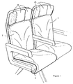
- Figure 1 is a perspective view, from the front, of a pair of aircraft seats each forming the first embodiment of the invention,
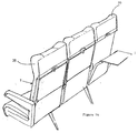
- Figure 2 is a perspective view, from the rear, of three aircraft seats of the form shown in Figure 1,
- Figure 3 is a view similar to that of Figure 1 but with removable headrests removed and one front cover partially removed,
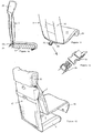
- Figure 4 shows the front cover removed from the seat and in a compact folded condition,
- Figure 5 is a fragmentary view illustrating the attachment of a foam cushion to a frame of the seat,
- Figure 6 illustrates two components of a plastics clip,
- Figure 7 illustrates the attachment of the front cover to the seat frame assembly,
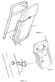
- Figures 8 to 10 illustrate the attachment of a semi-rigid back panel to the seat frame assembly,
- Figure 11 illustrates the front cover unfolded and ready to be fitted to the seat frame assembly,
- Figure 12 illustrates a two-pan clasp for attaching the front cover to the seat frame assembly,
- Figure 13 is a front perspective view showing a pair of seats each forming the second embodiment of the invention,
- Figure 14 is a perspective view, from the rear, of a group of three seats of the form shown in Figure 13,
- Figure 15 is a perspective view showing the attachment of a front cover to a seat frame assembly of the second embodiment of seat,
- Figure 16 is a side view, partially sectioned, of the second embodiment of seat,
- Figure 17 shows the attachment of a semi-rigid back panel to the seat frame assembly of the seat of Figures 13 to 16,
- Figure 18 is a detail view illustrating press stud fasteners used in the attachment of Figure 17,
- Figure 19 is a fragmentary sectional view through the semi-rigid back panel of Figure 8 or Figure 17,
- Figure 20 illustrates modifications to the foam cushion attachment illustrated in Figure 5,
- Figure 21 illustrates a further modification to the arrangement of Figure 5, and
- Figure 22 is a sectional view through the assembled seat portion of the seat of Figure 21.
-
- The aircraft seat forming the first embodiment of the invention has a rigid frame 1 (Figure 5) made from
tubular alloy 2 and panels made from alloy or a plastics composite material known as Dymetrol. Theframe 1 defines aseat portion 3 and a back portion 4, as best illustrated in Figure 5. Afoam cushion 5 is attached to the rigid frame to form a seat frame assembly. The outer edge of thefoam cushion 5 is covered byfabric 6. The seat andback portions 3 and 4 of this frame assembly are covered by afront cover 7, and a semi-rigid back panel 8 covers the rear surface of the back of the frame assembly. - The two-component plastics clip shown in Figure 6 is used in several places in the seat. This clip is similar to that used in conventional luggage retention systems. One
component 9 of the clip is in the shape of a socket having an elongated loop defining acentral aperture 10. Theother component 12 of the clip is in the form of a plug and has a base 13 on which is pivotally mounted atoggle 14 which can be turned between a locking position (illustrated) and a release position, displaced by 90° from the locking position. When in the release position, thetoggle 14 can be inserted into theaperture 10 and locked in position by rotating thetoggle 14 though 90° to its locking position. Release from the locking position is effected by rotating thetoggle 14 through 90° to its release position, enabling the twocomponents - In order to attach the
foam cushion 5 to theseat portion 3, two clips of the form shown in Figure 6 are used. Thesockets 9 of the clips are attached to theseat portion 3 in the positions illustrated in Figure 5, and theplug components 12 of the clips are attached to the underside of thefoam cushion 5, so that placement of thefoam cushion 5 on theseat portion 3 causes thetoggles 14 to register with and pass through theapertures 10, enabling thetoggles 14 to be rotated to their locking positions. Thefoam cushion 5 is thereby attached to the frame in the required position from which it cannot be removed or displaced, except by releasing the clips. - Similar clips are used to attach the
front cover 7 to the seat frame assembly. At the top of itsback portion 16, the front cover has two upwardly projecting ears 15 (Figure 3), each carrying aclip socket 9. The area of the frame covered by the headrests carries two clip plugs 12 which co-operate with the twosockets 9 to provide detachable connection and accurate location of the upper part of thefront cover 7 with respect to the frame assembly. - The
seat portion 17 of thefront cover 7 is made of sufficient length to form, at itsfront edge 18, (Figure 7) a flap which is folded over the front edge of thefoam cushion 5, the edge of thisflap 18 carrying threeclip sockets 9 respectively engageable with three clip plugs 12 on the front underside of thefoam cushion 5, these three clip plugs being best shown in Figure 5. - The transition between the seat and
back portions front cover 7 is formed by a curved line ofstitching 20 which is concave (when the cover is viewed from the front) so that thefront cover 7 fits neatly in position on the frame assembly. The curved shape of thisline 20 also means that thefront cover 7 can be folded about thiscurved line 20 to occupy a compact folded condition, as illustrated in Figure 4. - It is desirable to attach the area of the
curved line 20 to the seat frame, and this is achieved by a plastics clasp (Figure 12) having asocket portion 22 attached to the front cover by a short length ofwebbing 23, at or adjacent thecurved line 20, and aplug portion 24 attached to the seat frame by a short length of webbing. -
Upholstered headrests 25 conceal the clips used to attach theears 15 of thefront cover 7. As a consequence, all the attachments of thefront cover 7 to the seat frame assembly are hidden from normal view. The headrest mountings, which provide vertical adjustment for theheadrests 25, are shown at 26 in Figure 3. - The rear surface of the frame assembly is covered by a semi-rigid back panel 27 (Figures 2 and 8) which is moulded to the required shape and has a composite construction employing a layer of semi-rigid foam which is in turn covered by a fabric layer. This composite material is similar to that used for roof linings for cars.
- Referring to Figure 8, the
semi-rigid back panel 27 has edge flanges with holes for attaching theback panel 27 to the seat frame, these edge flanges being twoside flanges 28 and alower edge flange 29. The side flanges 28 are folded around the side members of the frame and are attached to the frame, from the front, byfasteners 30 of the type illustrated in Figure 10. Eachfastener 30 has aserrated shank 32 and a head with a cross slot for ease of turning, theshank 32 being passed through the hole in the flange so as to enter a hole in the frame, thefastener 30 being turned through 90° to release or fasten it in position. Thelower edge flange 29 is attached to a horizontal member of the frame by similar fasteners. - As shown in Figure 9, a
fabric panel 33 is stitched or adhered to the front of the upper region of theback panel 27. Arectangular aperture 34 in thepanel 33 accommodates the headrest mounting 26. - Figures 13 to 19 illustrate a second embodiment of seat which differs from the first embodiment principally in that the
front cover 7 has an integrally formedhood 35 which fits over an upper upholstered region of the frame, in place of the separate headrests of Figures 1 to 12. In Figures 13 to 19 similar pans to those of Figures 1 to 12 bear the same reference numerals. - In common with the seat of Figures 1 to 12, the seat of Figures 13 to 19 has a
foam cushion 5 attached to the seat frame by plastics clips of the form shown in Figure 6, and afront cover 7 attached to the underside of thecushion 5 by clips and to the frame by a clasp. However, the upper part of thefront cover 7 is located in position by thehood 35 which is in the shape of an inverted pocket and which fits neatly over the headrest region of the seat, as shown in Figure 16. - The
back panel 27 of the embodiment of Figures 13 to 19 does not cover the rear of the backrest region, but terminates in an upper edge 36 (Figure 17) adjacent to which is aretaining clip 37 for holding the usual hinge-down tray. Theflanges back panel 27 are detachably secured to the frame by press-studs havinginterengageable parts - The
back panel 27 of either embodiment is shown in section in Figure 19. Thepanel 27 is of composite construction, having asemi-rigid foam layer 40 sandwiched between a fabric, leather orleatherette skin 42 and abacking scrim 43. Thepanel 27 is formed in a mould to have the required shape to accommodate a leaflet pocket and receive a hinged tray. - The
front cover 7 is moulded using a double impression tool with the application of heat, pressure and adhesive to provide thefinished cover 7 with a three-dimensional shape conforming exactly to the complex three-dimensional shape presented by the seat frame assembly to which thecover 7 is to be fitted. This is particularly important where the seat frame assembly presents a concave shape where known covers tend to bridge the space or to require Velcro attachments. By moulding thefront cover 7 with a rear surface shape which conforms to the surface shape presented by the seat frame assembly, thefront cover 7 is an accurate and neat fit on the seat frame assembly. - To achieve the required three-dimensional shape of the front cover 7 (whether this has a hood or not), the
cover 7 is formed from a sandwich composite of backing scrim, flexible foam (which in practice is exfoliated graphite polyurethane foam) and front covering fabric, similar to the construction of thepanel 27 shown in Figure 19. - In each embodiment of seat, the
front cover 7 can be rapidly removed from the seat frame assembly by disengagement of the plastic clips and clasp. Removed covers 7 may be neatly folded and stacked in a compact condition for transport to the location where they are cleaned. Cleaned covers 7, similarly neatly folded and stacked, can then be fitted to the seat frame assemblies in a quick and accurate fashion, the accurate and positive interengagement of the clips and clasp ensuring firm retention and very accurate location of the front covers 7 with respect to the seat frame assemblies. The three-dimensional shaping of the covers to conform to the shape presented by the seat frame assemblies helps neat location and accurate fit. The front covers 7 are thus replaceable quickly and accurately by unskilled labour, in comparison with known systems which take longer, can easily be fitted incorrectly because of the reliance on Velcro and require a degree of acquired skill to achieve acceptable results. Moreover, the clips allow repeated attachment and removal of the covers with respect to the seat frame. - In the modifications of Figures 20 to 22, corresponding parts bear the same reference numerals as used in the preceding figures. In Figure 20, the
seat portions 3 havesocket components 9 at positions defining a particular pattern, so that aseat portion 3 is capable of accepting only cushions 5 with a matching or registering pattern ofplug components 12 on the cushion undersides. This pattern will normally consist of at least threesocket components 9 on eachseat portion 3 and at least three registeringplug components 12 on the underside of acushion 5, the pattern being capable of being defined by different positions and different spacings of thecomponents 9 and thecomponents 12 to provide any desired number of different patterns and resulting number of different acceptable combinations ofcushions 5 andseat portions 3. - Figure 20 illustrates three different patterns, one consisting of four locations and two of three locations. In each case, the
cushion 5 has a rounded front edge bearing threeplug components 12 for retaining the front edge of a cover, in a manner comparable to that illustrated in Figure 7. By providing theseat portions 3 and the undersides of thecushions 5 with particular patterns of cooperatingplug components 12 andsocket components 9, thecushions 5 are capable of being fitted only toparticular seat portions 3, ensuring that particular aircraft seats (eg aisle, window or centre seat in a bank of three) can only receive thecorrect cushions 5, an important matter if the cushions differ in shape, size, fabric covering or other property. The remainder of each seat illustrated in Figure 20 corresponds to the first embodiment illustrated in Figures 1 to 12, or Figure 20 could alternatively be regarded as a modification to the second embodiment illustrated in Figures 13 to 19. - Referring to Figures 21 and 22, the seat is modified by the incorporation of a
seat pan 44 which is preferably moulded to the required shape and may consist of a sandwich-like structure similar to thesemi-rigid back panel 27. Theseat pan 44 has a central recessed area surrounded by edge flanges, at least thefront edge flange 45 being moulded with a rounded shape in order closely to embrace the front edge of theseat portion 3. - The underside of the seat pan bears four
plug components 12 which respectively engage with foursocket components 9 in theseat portion 3, in order to provide positive and reliable (but detachable) connection of theseat pan 44 to theseat portion 3. Thecushion 5 is moulded to a shape which is complementary to the upper surface shape of theseat pan 44, affording a degree of location for thecushion 5 with respect of the seat pan and thus to theseat portion 3. - The
front edge flange 45 of theseat pan 44 has threeplug components 12 to locate the front edge of thefabric cover 7, in the manner illustrated in Figure 22. A further pair ofplug components 12 are located on the rear edge flange of theseat pan 44, these being engageable with a pair of socket components formed in thecover 7 at theline 20. It will be appreciated that these plug and socket components are provided instead of the clasp of Figure 12. - When fitted, the
cover 7 overwraps thecushion 5 and holds the latter in position in the recess in theseat pan 44. No plug or socket components are necessary on the cushion so that if the latter needs replacement no plug or socket components are lost.
Claims (5)
- A front cover (7) for fitting to an aircraft seat frame assembly, the front cover (7) comprising a seat portion (17) and a back portion (16) each formed by moulding to a three-dimensional shape conforming to the shape presented by the seat frame assembly, so that the front cover (7) is a neat and accurate fit on the seat frame assembly, the front cover (7) having formations (9) for cooperation with complementary formations (12) on the seat frame assembly, allowing for repeated attachment and removal of the front cover (7) with respect to the assembly.
- A front cover according to claim 1, wherein the seat portion (17) and the back portion (16) of the front cover (7) are joined along a curved line (20) which is concave when the front cover (7) is viewed from the front, the portions (17, 16) of the front cover (7) being foldable together about the curved line (2) to occupy a compact folded condition.
- A front cover according to claim 2, wherein each portion of the front cover (7) is of composite construction, having an intermediate layer of foam sandwiched between a backing scrim and a decorative top layer of fabric on the surface of the cover which is visible in use.
- An aircraft seat comprising a seat frame assembly and a front cover (7) according to any of the preceding claims.
- An aircraft seat according to claim 4, wherein the seat frame assembly comprises a rigid seat frame and a cushion (5) attached thereto, a front edge of the cover (7) being detachably secured to an underside front edge of the cushion (5) by said formations (9, 12).
Applications Claiming Priority (2)
| Application Number | Priority Date | Filing Date | Title |
|---|---|---|---|
| GBGB9824704.2A GB9824704D0 (en) | 1998-11-12 | 1998-11-12 | Aircraft seats |
| GB9824704 | 1998-11-12 |
Publications (3)
| Publication Number | Publication Date |
|---|---|
| EP1000856A2 true EP1000856A2 (en) | 2000-05-17 |
| EP1000856A3 EP1000856A3 (en) | 2001-01-10 |
| EP1000856B1 EP1000856B1 (en) | 2004-01-14 |
Family
ID=10842251
Family Applications (2)
| Application Number | Title | Priority Date | Filing Date |
|---|---|---|---|
| EP99305257A Expired - Lifetime EP1000856B1 (en) | 1998-11-12 | 1999-07-02 | Aircraft seats |
| EP99305256A Withdrawn EP1000855A3 (en) | 1998-11-12 | 1999-07-02 | Aircraft seats |
Family Applications After (1)
| Application Number | Title | Priority Date | Filing Date |
|---|---|---|---|
| EP99305256A Withdrawn EP1000855A3 (en) | 1998-11-12 | 1999-07-02 | Aircraft seats |
Country Status (12)
| Country | Link |
|---|---|
| US (1) | US6241188B1 (en) |
| EP (2) | EP1000856B1 (en) |
| JP (1) | JP4037022B2 (en) |
| AT (1) | ATE257795T1 (en) |
| AU (1) | AU745388B2 (en) |
| DE (1) | DE69914161T2 (en) |
| DK (1) | DK1000856T3 (en) |
| ES (1) | ES2213331T3 (en) |
| GB (1) | GB9824704D0 (en) |
| MY (1) | MY124705A (en) |
| PT (1) | PT1000856E (en) |
| SG (1) | SG87843A1 (en) |
Cited By (11)
| Publication number | Priority date | Publication date | Assignee | Title |
|---|---|---|---|---|
| WO2007061973A1 (en) * | 2005-11-21 | 2007-05-31 | Nightgear Llc | Seating accessory |
| DE102007007856A1 (en) * | 2007-02-16 | 2008-08-21 | Metzeler Schaum Gmbh | Seat, in particular passenger seat |
| EP2279905A1 (en) * | 2009-07-28 | 2011-02-02 | Centre d'Etude et de Recherche pour l'Automobile (CERA) | Automotive vehicle seat cushion |
| AU2007349199B2 (en) * | 2007-03-27 | 2012-03-01 | Nightgear Llc | Seating accessory |
| EP2457831A3 (en) * | 2010-11-25 | 2012-06-13 | MGR Foamtex Limited | Improvements in and relating to interior trim components for aircraft cabins |
| EP3075599A1 (en) * | 2015-03-30 | 2016-10-05 | G.I.A. | Seat cushion, seat for an agricultural implement comprising such a seat cushion, method for installing and using the seat cushion |
| WO2016166028A1 (en) * | 2015-04-13 | 2016-10-20 | Recaro Aircraft Seating Gmbh & Co Kg | Aircraft module covering device |
| WO2017037016A1 (en) * | 2015-09-02 | 2017-03-09 | Recaro Aircraft Seating Gmbh & Co. Kg | Airplane seat device |
| US10407174B2 (en) | 2014-12-31 | 2019-09-10 | ST Engineering Aerospace Ltd. | Seat suspension installation method and passenger seat |
| CZ308996B6 (en) * | 2020-09-17 | 2021-11-10 | IDEA AIR s.r.o. | Air seat |
| EP4501785A3 (en) * | 2015-04-13 | 2025-05-07 | Encore Seats, Inc. | Aircraft seating assembly |
Families Citing this family (61)
| Publication number | Priority date | Publication date | Assignee | Title |
|---|---|---|---|---|
| US5609395A (en) * | 1995-09-18 | 1997-03-11 | Burch; Selwyn A. | Modular bus seat and method of retrofitting existing bus seats |
| US20050269850A1 (en) * | 1999-11-24 | 2005-12-08 | Total Innovative Manufacturing, Llc | Removable seat cushion |
| FR2814709B1 (en) * | 2000-10-03 | 2003-02-07 | Peugeot Citroen Automobiles Sa | MOTOR VEHICLE SEAT |
| CA2581738C (en) | 2001-08-09 | 2009-04-14 | Virgin Atlantic Airways Limited | A seating system and a passenger accomodation unit for a vehicle |
| US6655736B1 (en) * | 2001-12-03 | 2003-12-02 | George Gabriel Arenas | Retractable seat protection cover |
| US6786546B2 (en) | 2002-05-01 | 2004-09-07 | Prince Lionheart, Inc. | Two-stage protective car seat cover for child and infant safety chairs |
| FR2847534B1 (en) * | 2002-11-27 | 2007-02-23 | Cera | SEAT FOR MOTOR VEHICLE COMPRISING A COVERING ELEMENT OF A RETRACTABLE TABLET SYSTEM |
| JP4216147B2 (en) * | 2003-02-13 | 2009-01-28 | 本田技研工業株式会社 | Vehicle seat |
| CN100460240C (en) * | 2003-02-13 | 2009-02-11 | 本田技研工业株式会社 | vehicle seat structure |
| USD495171S1 (en) | 2003-05-23 | 2004-08-31 | Be Aerospace, Inc. | Arm rest end cap |
| US20050055228A1 (en) * | 2003-09-08 | 2005-03-10 | Aircraft Protective Systems, Inc. | Management method of in-flight entertainment device rentals having self-contained audio-visual presentations |
| US20050055278A1 (en) * | 2003-09-08 | 2005-03-10 | Aircraft Protective Systems, Inc. | Payment method for in-flight entertainment device rentals having self-contained audio-visual presentations |
| US8403411B2 (en) * | 2003-12-15 | 2013-03-26 | Digecor, Inc. | Detachable seat mounted audio-visual entertainment system with locally storable, selectable, and updatable content |
| US6817664B1 (en) * | 2004-01-22 | 2004-11-16 | Jan Hao Tang | Automobile seat cover |
| USD583579S1 (en) | 2004-06-18 | 2008-12-30 | Virgin Atlantic Airways Limited | Airplane seating unit |
| JP4260124B2 (en) | 2005-03-01 | 2009-04-30 | 小糸工業株式会社 | Aircraft seat |
| FR2884772B1 (en) * | 2005-04-22 | 2007-06-08 | Peugeot Citroen Automobiles Sa | REMOVABLE CUSHION FOR A MOTOR VEHICLE SEAT, SEAT ASSEMBLY COMPRISING SUCH A CUSHION, AND CORRESPONDING MOTOR VEHICLE. |
| US7487575B2 (en) | 2005-07-13 | 2009-02-10 | Lyle J Smith | System for attaching trim covers to a flexible substrate |
| US20070284930A1 (en) * | 2006-06-09 | 2007-12-13 | Christianson Nicholas M | Chair having removable back or seat cushion assemblies and methods related thereto |
| JP2008239042A (en) * | 2007-03-28 | 2008-10-09 | Yokohama Rubber Co Ltd:The | Restroom for aircraft |
| US8091184B2 (en) | 2007-04-19 | 2012-01-10 | Hope Global, Division Of Nfa Corp. | Festooned trim clip system and method for attaching festooned clips to a substrate |
| US8141948B2 (en) * | 2007-05-11 | 2012-03-27 | Audiovox Corporation | Seat back entertainment system |
| US8099837B2 (en) | 2007-09-07 | 2012-01-24 | Hope Global, Division Of Nfa Corporation | Low-profile upholstery clip for attaching a bead to a foam substrate |
| US7946649B2 (en) * | 2007-10-01 | 2011-05-24 | Lear Corporation | Vehicle seat assembly having layered seating system with attachment member |
| US8272694B2 (en) * | 2008-07-08 | 2012-09-25 | B/E Aerospace, Inc. | Articulating passenger seat |
| US8991930B2 (en) * | 2008-09-22 | 2015-03-31 | Johnson Controls Technology Company | Closed cell foam vehicle interior component and method of making same |
| US7862116B2 (en) * | 2008-12-16 | 2011-01-04 | Ami Industries, Inc. | Cushion for aircraft ejection seat |
| MY151916A (en) * | 2009-03-18 | 2014-07-31 | Seatcoverpro Sdn Bhd | Vehicle seat cover |
| JP5524564B2 (en) * | 2009-10-19 | 2014-06-18 | 株式会社岡村製作所 | Chair back |
| US20110148155A1 (en) * | 2009-12-22 | 2011-06-23 | Mattel, Inc. | Collapsible Infant Support |
| USD665182S1 (en) | 2010-01-14 | 2012-08-14 | Air New Zealand Limited | Aircraft seat unit |
| FR2973336A1 (en) * | 2011-03-30 | 2012-10-05 | Expliseat Sas | AIRCRAFT SEAT WITH FLEXIBLE FEATURE |
| US9505329B2 (en) * | 2011-05-02 | 2016-11-29 | Toyota Jidosha Kabushiki Kaisha | Vehicle seat and seat back board |
| DE102011077773A1 (en) * | 2011-06-17 | 2012-12-20 | Voith Patent Gmbh | Stowable couch for installation in a passenger vehicle |
| JP2013052757A (en) * | 2011-09-05 | 2013-03-21 | Toyota Boshoku Corp | Vehicle seat |
| DE102011055286A1 (en) * | 2011-10-17 | 2013-04-18 | Grammer Ag | Vehicle seat, in particular rail vehicle seat, with a cushion element fastening frame |
| US9545863B2 (en) * | 2011-11-25 | 2017-01-17 | Kenneth Alfano | Legroom cavity in vehicle backrest for rear-faced child in carseat |
| USD708886S1 (en) * | 2012-11-09 | 2014-07-15 | Optimares S.P.A. | Headrest for seats |
| USD723819S1 (en) * | 2013-01-22 | 2015-03-10 | Central Japan Railway Company | Vehicle seat |
| USD724338S1 (en) * | 2013-07-09 | 2015-03-17 | Etihad Airways | Row of seats |
| AU354155S (en) * | 2013-07-09 | 2014-03-04 | Etihad Airways | Headrest |
| USD724337S1 (en) * | 2013-07-09 | 2015-03-17 | Etihad Airways | Row of seats |
| US20150036060A1 (en) * | 2013-07-31 | 2015-02-05 | Airgo Design Pte. Ltd. | Passenger Delivery System |
| EP3074307A1 (en) * | 2013-11-27 | 2016-10-05 | B/E Aerospace, Inc. | Carry-on passenger seat |
| USD723822S1 (en) * | 2014-03-28 | 2015-03-10 | Superalloy Industrial Co., Ltd. | Aircraft seat |
| USD724339S1 (en) * | 2014-03-28 | 2015-03-17 | Superalloy Industrial Co., Ltd. | Aircraft seat |
| GB2530743B (en) * | 2014-09-30 | 2021-06-09 | Thompson Aero Seating Ltd | A Panel Assembly |
| USD772625S1 (en) | 2014-11-26 | 2016-11-29 | Mattel, Inc. | Infant support structure with a rocking device |
| USD807668S1 (en) * | 2014-12-02 | 2018-01-16 | Kehei Traveler Corporation | Seat cover |
| DE102015104744A1 (en) * | 2015-03-27 | 2016-09-29 | Lisa Dräxlmaier GmbH | Seat cover for an aircraft seat |
| US9834431B2 (en) | 2015-08-28 | 2017-12-05 | Hope Global, Division Of Nfa Corp. | Listing bead for upholstery clips |
| DE102015016488A1 (en) * | 2015-12-18 | 2017-06-22 | GM Global Technology Operations LLC (n. d. Gesetzen des Staates Delaware) | A method for producing a support structure for the backrest of a motor vehicle seat and support structure for the backrest of a motor vehicle seat |
| US10624456B2 (en) * | 2016-02-05 | 2020-04-21 | Jose Ismael Fernandez | Portable seat cushion |
| DE102016108285A1 (en) | 2016-05-04 | 2017-11-09 | Lisa Dräxlmaier GmbH | Seat cover for an aircraft seat |
| US10703232B2 (en) * | 2016-07-20 | 2020-07-07 | Tachi-S Co., Ltd. | Vehicle seat |
| US10473136B2 (en) | 2017-05-25 | 2019-11-12 | Ford Global Technologies, Llc | Vehicle seating cushion with snap-fit fasteners to interconnect with snap-fit receivers on a structural support |
| CN110015220B (en) * | 2019-04-25 | 2024-03-29 | 傲科塑料制品(张家港)有限公司 | Non-woven fabric plastic cloth clamping strip structure of automobile seat sleeve |
| US11142322B1 (en) * | 2020-08-31 | 2021-10-12 | B/E Aerospace, Inc. | Attachment assembly for a dress cover and a cushion of an aircraft seat |
| US11708164B2 (en) * | 2021-04-20 | 2023-07-25 | B/E Aerospace, Inc. | Combination energy impact attenuation, vibration mitigation and flotation device for aircraft seating applications |
| FR3144572B1 (en) * | 2023-01-03 | 2025-03-21 | Faurecia Sieges Dautomobile | Modular seat cushion comprising a modular side bolster, and seat assembly comprising such a cushion and such a bolster |
| US20250089909A1 (en) * | 2023-09-19 | 2025-03-20 | Jonathon Mark Bryan | Cooling seat cover systems and methods |
Family Cites Families (13)
| Publication number | Priority date | Publication date | Assignee | Title |
|---|---|---|---|---|
| US2798524A (en) * | 1956-11-28 | 1957-07-09 | Chester R Ryon | Handbag and replaceable wraparound cover flap therefor |
| US3199916A (en) | 1964-05-11 | 1965-08-10 | Sebastian P Chiarenza | Car upholstery cover |
| GB1160398A (en) | 1966-11-02 | 1969-08-06 | Pininfarina Spa Carrozzeria | Seat Covers. |
| US3848925A (en) * | 1972-11-02 | 1974-11-19 | Coach & Car Equip Corp | Transit vehicle seat |
| US3861747A (en) * | 1972-12-11 | 1975-01-21 | Norman Diamond | Modular seat for public use |
| JPS5555651Y2 (en) | 1975-02-03 | 1980-12-23 | ||
| US4103968A (en) * | 1977-06-09 | 1978-08-01 | Caterpillar Tractor Co. | Seat cover |
| DE2902386A1 (en) | 1979-01-23 | 1980-07-24 | Vogel Ignaz Fahrzeugsitze | SEAT |
| US4627587A (en) * | 1984-07-18 | 1986-12-09 | Diane R. McCutchan | Airplane seat with convertible flotation-cushion system |
| US4887865A (en) | 1988-11-08 | 1989-12-19 | Daniel Dawidzon | Orthopedic seat and backrest combination |
| CA2016270A1 (en) | 1989-06-08 | 1990-12-08 | Duane W. Witzke | Vehicle seat with blow molded cover and method of making the same |
| US5007676A (en) | 1989-10-12 | 1991-04-16 | Jack Lien | Quick detachable vehicle seat cover |
| DE9311243U1 (en) * | 1993-07-28 | 1993-09-16 | Camloc GmbH, 65779 Kelkheim | Twist lock |
-
1998
- 1998-11-12 GB GBGB9824704.2A patent/GB9824704D0/en not_active Ceased
-
1999
- 1999-06-02 US US09/324,215 patent/US6241188B1/en not_active Expired - Lifetime
- 1999-07-02 ES ES99305257T patent/ES2213331T3/en not_active Expired - Lifetime
- 1999-07-02 EP EP99305257A patent/EP1000856B1/en not_active Expired - Lifetime
- 1999-07-02 EP EP99305256A patent/EP1000855A3/en not_active Withdrawn
- 1999-07-02 DE DE69914161T patent/DE69914161T2/en not_active Expired - Lifetime
- 1999-07-02 AT AT99305257T patent/ATE257795T1/en not_active IP Right Cessation
- 1999-07-02 DK DK99305257T patent/DK1000856T3/en active
- 1999-07-02 PT PT99305257T patent/PT1000856E/en unknown
- 1999-10-27 SG SG9905358A patent/SG87843A1/en unknown
- 1999-11-10 AU AU59319/99A patent/AU745388B2/en not_active Expired
- 1999-11-11 MY MYPI99004916A patent/MY124705A/en unknown
- 1999-11-11 JP JP32112099A patent/JP4037022B2/en not_active Expired - Lifetime
Non-Patent Citations (1)
| Title |
|---|
| None |
Cited By (17)
| Publication number | Priority date | Publication date | Assignee | Title |
|---|---|---|---|---|
| WO2007061973A1 (en) * | 2005-11-21 | 2007-05-31 | Nightgear Llc | Seating accessory |
| DE102007007856A1 (en) * | 2007-02-16 | 2008-08-21 | Metzeler Schaum Gmbh | Seat, in particular passenger seat |
| AU2007349199B2 (en) * | 2007-03-27 | 2012-03-01 | Nightgear Llc | Seating accessory |
| EP2279905A1 (en) * | 2009-07-28 | 2011-02-02 | Centre d'Etude et de Recherche pour l'Automobile (CERA) | Automotive vehicle seat cushion |
| FR2948615A1 (en) * | 2009-07-28 | 2011-02-04 | Cera | MOTOR VEHICLE SEAT CUSHION |
| GB2485822B (en) * | 2010-11-25 | 2018-02-21 | Mgr Foamtex Ltd | Improvements in and relating to interior trim components for aircraft cabins |
| EP2457831A3 (en) * | 2010-11-25 | 2012-06-13 | MGR Foamtex Limited | Improvements in and relating to interior trim components for aircraft cabins |
| US9511864B2 (en) | 2010-11-25 | 2016-12-06 | Mgr Foamtex Limited | Interior trim components for aircraft cabins |
| US10407174B2 (en) | 2014-12-31 | 2019-09-10 | ST Engineering Aerospace Ltd. | Seat suspension installation method and passenger seat |
| EP3075599A1 (en) * | 2015-03-30 | 2016-10-05 | G.I.A. | Seat cushion, seat for an agricultural implement comprising such a seat cushion, method for installing and using the seat cushion |
| FR3034366A1 (en) * | 2015-03-30 | 2016-10-07 | G I A | SEAT CUSHION, SEAT FOR AGRICULTURAL EQUIPMENT COMPRISING SUCH A SEAT CUSHION, METHOD OF INSTALLATION AND USE OF THE SEAT CUSHION |
| WO2016166028A1 (en) * | 2015-04-13 | 2016-10-20 | Recaro Aircraft Seating Gmbh & Co Kg | Aircraft module covering device |
| US20180170548A1 (en) * | 2015-04-13 | 2018-06-21 | Recaro Aircraft Seating Gmbh & Co. Kg | Aircraft module covering device |
| EP4501785A3 (en) * | 2015-04-13 | 2025-05-07 | Encore Seats, Inc. | Aircraft seating assembly |
| WO2017037016A1 (en) * | 2015-09-02 | 2017-03-09 | Recaro Aircraft Seating Gmbh & Co. Kg | Airplane seat device |
| US10661905B2 (en) | 2015-09-02 | 2020-05-26 | Recaro Aircraft Seating Gmbh & Co. Kg | Airplane seat device |
| CZ308996B6 (en) * | 2020-09-17 | 2021-11-10 | IDEA AIR s.r.o. | Air seat |
Also Published As
| Publication number | Publication date |
|---|---|
| EP1000855A3 (en) | 2001-01-10 |
| DE69914161T2 (en) | 2004-10-28 |
| PT1000856E (en) | 2004-05-31 |
| EP1000856A3 (en) | 2001-01-10 |
| EP1000856B1 (en) | 2004-01-14 |
| DK1000856T3 (en) | 2004-04-19 |
| JP2000272597A (en) | 2000-10-03 |
| HK1028222A1 (en) | 2001-02-09 |
| EP1000855A2 (en) | 2000-05-17 |
| ES2213331T3 (en) | 2004-08-16 |
| ATE257795T1 (en) | 2004-01-15 |
| DE69914161D1 (en) | 2004-02-19 |
| AU745388B2 (en) | 2002-03-21 |
| JP4037022B2 (en) | 2008-01-23 |
| SG87843A1 (en) | 2002-04-16 |
| MY124705A (en) | 2006-06-30 |
| GB9824704D0 (en) | 1999-01-06 |
| US6241188B1 (en) | 2001-06-05 |
| AU5931999A (en) | 2000-05-18 |
Similar Documents
| Publication | Publication Date | Title |
|---|---|---|
| EP1000856B1 (en) | Aircraft seats | |
| US6088855A (en) | Cervical neck support for children | |
| US8814268B2 (en) | Vehicle seat and clip | |
| US8454085B1 (en) | Vehicle seats having upwardly extending side guards | |
| CN201342960Y (en) | Vehicle seat | |
| PT8285U (en) | PADS WITH PERMUTABLE COVER | |
| JP2016097948A (en) | Sheet | |
| JP2000070078A (en) | Seat for vehicle | |
| CN105620314B (en) | Seat-assembly with detachable cushion insertion piece | |
| US12466297B1 (en) | Removable trim cover with headrest guide | |
| US20230048263A1 (en) | Vehicle seat | |
| CN110103792B (en) | Trim part for a base of a vehicle seat and method for producing a trim part | |
| JP2012121440A (en) | Seat for vehicle | |
| HK1028222B (en) | Aircraft seats | |
| HK1027785A (en) | Aircraft seats | |
| US11654804B2 (en) | Trim cover attachment with faux hole design | |
| US10358064B2 (en) | Headrest cover | |
| CN213442212U (en) | Chair | |
| US20260001505A1 (en) | Bolster | |
| JP4524013B2 (en) | Chair cushion mounting structure | |
| JP2013103630A (en) | Seat cover | |
| JPH0243277Y2 (en) | ||
| JP6974136B2 (en) | Vehicle seat | |
| CN223934587U (en) | Automobile seat cushion | |
| JP3771387B2 (en) | Seat back, seat back replacement method, and seat back manufacturing method |
Legal Events
| Date | Code | Title | Description |
|---|---|---|---|
| PUAI | Public reference made under article 153(3) epc to a published international application that has entered the european phase |
Free format text: ORIGINAL CODE: 0009012 |
|
| AK | Designated contracting states |
Kind code of ref document: A2 Designated state(s): AT BE CH CY DE DK ES FI FR GB GR IE IT LI LU MC NL PT SE |
|
| AX | Request for extension of the european patent |
Free format text: AL;LT;LV;MK;RO;SI |
|
| PUAL | Search report despatched |
Free format text: ORIGINAL CODE: 0009013 |
|
| AK | Designated contracting states |
Kind code of ref document: A3 Designated state(s): AT BE CH CY DE DK ES FI FR GB GR IE IT LI LU MC NL PT SE |
|
| AX | Request for extension of the european patent |
Free format text: AL;LT;LV;MK;RO;SI |
|
| 17P | Request for examination filed |
Effective date: 20010130 |
|
| AKX | Designation fees paid |
Free format text: AT BE CH CY DE DK ES FI FR GB GR IE IT LI LU MC NL PT SE |
|
| 17Q | First examination report despatched |
Effective date: 20021219 |
|
| GRAH | Despatch of communication of intention to grant a patent |
Free format text: ORIGINAL CODE: EPIDOS IGRA |
|
| GRAS | Grant fee paid |
Free format text: ORIGINAL CODE: EPIDOSNIGR3 |
|
| GRAA | (expected) grant |
Free format text: ORIGINAL CODE: 0009210 |
|
| AK | Designated contracting states |
Kind code of ref document: B1 Designated state(s): AT BE CH CY DE DK ES FI FR GB GR IE IT LI LU MC NL PT SE |
|
| PG25 | Lapsed in a contracting state [announced via postgrant information from national office to epo] |
Ref country code: CY Free format text: LAPSE BECAUSE OF FAILURE TO SUBMIT A TRANSLATION OF THE DESCRIPTION OR TO PAY THE FEE WITHIN THE PRESCRIBED TIME-LIMIT Effective date: 20040114 Ref country code: BE Free format text: LAPSE BECAUSE OF FAILURE TO SUBMIT A TRANSLATION OF THE DESCRIPTION OR TO PAY THE FEE WITHIN THE PRESCRIBED TIME-LIMIT Effective date: 20040114 |
|
| REG | Reference to a national code |
Ref country code: GB Ref legal event code: FG4D |
|
| REG | Reference to a national code |
Ref country code: CH Ref legal event code: EP |
|
| REG | Reference to a national code |
Ref country code: IE Ref legal event code: FG4D |
|
| REF | Corresponds to: |
Ref document number: 69914161 Country of ref document: DE Date of ref document: 20040219 Kind code of ref document: P |
|
| PG25 | Lapsed in a contracting state [announced via postgrant information from national office to epo] |
Ref country code: GR Free format text: LAPSE BECAUSE OF FAILURE TO SUBMIT A TRANSLATION OF THE DESCRIPTION OR TO PAY THE FEE WITHIN THE PRESCRIBED TIME-LIMIT Effective date: 20040414 |
|
| REG | Reference to a national code |
Ref country code: CH Ref legal event code: NV Representative=s name: PATENTANWAELTE FELDMANN & PARTNER AG |
|
| REG | Reference to a national code |
Ref country code: DK Ref legal event code: T3 |
|
| REG | Reference to a national code |
Ref country code: SE Ref legal event code: TRGR |
|
| REG | Reference to a national code |
Ref country code: PT Ref legal event code: SC4A Free format text: AVAILABILITY OF NATIONAL TRANSLATION Effective date: 20040326 |
|
| REG | Reference to a national code |
Ref country code: HK Ref legal event code: GR Ref document number: 1028222 Country of ref document: HK |
|
| PG25 | Lapsed in a contracting state [announced via postgrant information from national office to epo] |
Ref country code: LU Free format text: LAPSE BECAUSE OF NON-PAYMENT OF DUE FEES Effective date: 20040702 |
|
| PG25 | Lapsed in a contracting state [announced via postgrant information from national office to epo] |
Ref country code: MC Free format text: LAPSE BECAUSE OF NON-PAYMENT OF DUE FEES Effective date: 20040731 |
|
| REG | Reference to a national code |
Ref country code: ES Ref legal event code: FG2A Ref document number: 2213331 Country of ref document: ES Kind code of ref document: T3 |
|
| ET | Fr: translation filed | ||
| PLBE | No opposition filed within time limit |
Free format text: ORIGINAL CODE: 0009261 |
|
| STAA | Information on the status of an ep patent application or granted ep patent |
Free format text: STATUS: NO OPPOSITION FILED WITHIN TIME LIMIT |
|
| 26N | No opposition filed |
Effective date: 20041015 |
|
| PGFP | Annual fee paid to national office [announced via postgrant information from national office to epo] |
Ref country code: AT Payment date: 20050609 Year of fee payment: 7 |
|
| PGFP | Annual fee paid to national office [announced via postgrant information from national office to epo] |
Ref country code: DK Payment date: 20050614 Year of fee payment: 7 |
|
| PGFP | Annual fee paid to national office [announced via postgrant information from national office to epo] |
Ref country code: FI Payment date: 20050616 Year of fee payment: 7 |
|
| PGFP | Annual fee paid to national office [announced via postgrant information from national office to epo] |
Ref country code: IE Payment date: 20050620 Year of fee payment: 7 |
|
| PGFP | Annual fee paid to national office [announced via postgrant information from national office to epo] |
Ref country code: PT Payment date: 20050621 Year of fee payment: 7 |
|
| PGFP | Annual fee paid to national office [announced via postgrant information from national office to epo] |
Ref country code: ES Payment date: 20050705 Year of fee payment: 7 |
|
| PGFP | Annual fee paid to national office [announced via postgrant information from national office to epo] |
Ref country code: CH Payment date: 20060615 Year of fee payment: 8 |
|
| PG25 | Lapsed in a contracting state [announced via postgrant information from national office to epo] |
Ref country code: FI Free format text: LAPSE BECAUSE OF NON-PAYMENT OF DUE FEES Effective date: 20060702 Ref country code: AT Free format text: LAPSE BECAUSE OF NON-PAYMENT OF DUE FEES Effective date: 20060702 |
|
| PG25 | Lapsed in a contracting state [announced via postgrant information from national office to epo] |
Ref country code: IE Free format text: LAPSE BECAUSE OF NON-PAYMENT OF DUE FEES Effective date: 20060703 |
|
| PG25 | Lapsed in a contracting state [announced via postgrant information from national office to epo] |
Ref country code: DK Free format text: LAPSE BECAUSE OF NON-PAYMENT OF DUE FEES Effective date: 20060731 |
|
| PGFP | Annual fee paid to national office [announced via postgrant information from national office to epo] |
Ref country code: IT Payment date: 20060731 Year of fee payment: 8 |
|
| PG25 | Lapsed in a contracting state [announced via postgrant information from national office to epo] |
Ref country code: PT Free format text: LAPSE BECAUSE OF NON-PAYMENT OF DUE FEES Effective date: 20070102 |
|
| REG | Reference to a national code |
Ref country code: PT Ref legal event code: MM4A Free format text: LAPSE DUE TO NON-PAYMENT OF FEES Effective date: 20070102 |
|
| REG | Reference to a national code |
Ref country code: DK Ref legal event code: EBP |
|
| REG | Reference to a national code |
Ref country code: IE Ref legal event code: MM4A |
|
| REG | Reference to a national code |
Ref country code: CH Ref legal event code: PFA Owner name: MGR FOAMTEX LIMITED Free format text: MGR FOAMTEX LIMITED#UNITS 10-12, JEFFERSON WAY#THAME, OXFORDSHIRE OX9 3SZ (GB) -TRANSFER TO- MGR FOAMTEX LIMITED#UNITS 10-12, JEFFERSON WAY#THAME, OXFORDSHIRE OX9 3SZ (GB) |
|
| REG | Reference to a national code |
Ref country code: ES Ref legal event code: FD2A Effective date: 20060703 |
|
| PG25 | Lapsed in a contracting state [announced via postgrant information from national office to epo] |
Ref country code: ES Free format text: LAPSE BECAUSE OF NON-PAYMENT OF DUE FEES Effective date: 20060703 |
|
| REG | Reference to a national code |
Ref country code: CH Ref legal event code: PL |
|
| PG25 | Lapsed in a contracting state [announced via postgrant information from national office to epo] |
Ref country code: LI Free format text: LAPSE BECAUSE OF NON-PAYMENT OF DUE FEES Effective date: 20070731 Ref country code: CH Free format text: LAPSE BECAUSE OF NON-PAYMENT OF DUE FEES Effective date: 20070731 |
|
| PG25 | Lapsed in a contracting state [announced via postgrant information from national office to epo] |
Ref country code: IT Free format text: LAPSE BECAUSE OF NON-PAYMENT OF DUE FEES Effective date: 20070702 |
|
| REG | Reference to a national code |
Ref country code: FR Ref legal event code: PLFP Year of fee payment: 18 |
|
| REG | Reference to a national code |
Ref country code: DE Ref legal event code: R082 Ref document number: 69914161 Country of ref document: DE Representative=s name: MICHALSKI HUETTERMANN & PARTNER PATENTANWAELTE, DE |
|
| REG | Reference to a national code |
Ref country code: FR Ref legal event code: PLFP Year of fee payment: 19 |
|
| REG | Reference to a national code |
Ref country code: FR Ref legal event code: PLFP Year of fee payment: 20 |
|
| PGFP | Annual fee paid to national office [announced via postgrant information from national office to epo] |
Ref country code: DE Payment date: 20180723 Year of fee payment: 20 Ref country code: NL Payment date: 20180719 Year of fee payment: 20 Ref country code: FR Payment date: 20180725 Year of fee payment: 20 Ref country code: GB Payment date: 20180530 Year of fee payment: 20 |
|
| PGFP | Annual fee paid to national office [announced via postgrant information from national office to epo] |
Ref country code: SE Payment date: 20180719 Year of fee payment: 20 |
|
| REG | Reference to a national code |
Ref country code: DE Ref legal event code: R071 Ref document number: 69914161 Country of ref document: DE |
|
| REG | Reference to a national code |
Ref country code: NL Ref legal event code: MK Effective date: 20190701 |
|
| REG | Reference to a national code |
Ref country code: GB Ref legal event code: PE20 Expiry date: 20190701 |
|
| PG25 | Lapsed in a contracting state [announced via postgrant information from national office to epo] |
Ref country code: GB Free format text: LAPSE BECAUSE OF EXPIRATION OF PROTECTION Effective date: 20190701 |