EP1000883B1 - Fördervorrichtung für Produkte, insbesondere Früchte - Google Patents
Fördervorrichtung für Produkte, insbesondere Früchte Download PDFInfo
- Publication number
- EP1000883B1 EP1000883B1 EP99390021A EP99390021A EP1000883B1 EP 1000883 B1 EP1000883 B1 EP 1000883B1 EP 99390021 A EP99390021 A EP 99390021A EP 99390021 A EP99390021 A EP 99390021A EP 1000883 B1 EP1000883 B1 EP 1000883B1
- Authority
- EP
- European Patent Office
- Prior art keywords
- conveyor
- support
- conveyor device
- longitudinal
- carrier arms
- Prior art date
- Legal status (The legal status is an assumption and is not a legal conclusion. Google has not performed a legal analysis and makes no representation as to the accuracy of the status listed.)
- Expired - Lifetime
Links
- 235000013399 edible fruits Nutrition 0.000 title claims description 19
- 230000002093 peripheral effect Effects 0.000 claims description 17
- 238000012423 maintenance Methods 0.000 claims description 5
- 239000006260 foam Substances 0.000 claims description 3
- 238000006073 displacement reaction Methods 0.000 claims 1
- 238000011144 upstream manufacturing Methods 0.000 claims 1
- 230000000994 depressogenic effect Effects 0.000 abstract 1
- 235000013311 vegetables Nutrition 0.000 description 8
- 238000005303 weighing Methods 0.000 description 4
- 208000031968 Cadaver Diseases 0.000 description 3
- 239000004698 Polyethylene Substances 0.000 description 3
- XAGFODPZIPBFFR-UHFFFAOYSA-N aluminium Chemical compound [Al] XAGFODPZIPBFFR-UHFFFAOYSA-N 0.000 description 3
- 229910052782 aluminium Inorganic materials 0.000 description 3
- 210000000056 organ Anatomy 0.000 description 3
- -1 polyethylene Polymers 0.000 description 3
- 229920000573 polyethylene Polymers 0.000 description 3
- 238000002347 injection Methods 0.000 description 2
- 239000007924 injection Substances 0.000 description 2
- WWYNJERNGUHSAO-XUDSTZEESA-N (+)-Norgestrel Chemical compound O=C1CC[C@@H]2[C@H]3CC[C@](CC)([C@](CC4)(O)C#C)[C@@H]4[C@@H]3CCC2=C1 WWYNJERNGUHSAO-XUDSTZEESA-N 0.000 description 1
- 229930182556 Polyacetal Natural products 0.000 description 1
- 241000220324 Pyrus Species 0.000 description 1
- 239000006096 absorbing agent Substances 0.000 description 1
- 230000032683 aging Effects 0.000 description 1
- 239000004411 aluminium Substances 0.000 description 1
- 238000009362 arboriculture Methods 0.000 description 1
- 230000001174 ascending effect Effects 0.000 description 1
- 230000000903 blocking effect Effects 0.000 description 1
- 229910003460 diamond Inorganic materials 0.000 description 1
- 239000010432 diamond Substances 0.000 description 1
- 230000008030 elimination Effects 0.000 description 1
- 238000003379 elimination reaction Methods 0.000 description 1
- 235000012055 fruits and vegetables Nutrition 0.000 description 1
- 238000004519 manufacturing process Methods 0.000 description 1
- 239000000463 material Substances 0.000 description 1
- 230000003287 optical effect Effects 0.000 description 1
- 235000021017 pears Nutrition 0.000 description 1
- 229920006324 polyoxymethylene Polymers 0.000 description 1
- 238000005096 rolling process Methods 0.000 description 1
- 238000000926 separation method Methods 0.000 description 1
- 230000001960 triggered effect Effects 0.000 description 1
Images


Classifications
-
- B—PERFORMING OPERATIONS; TRANSPORTING
- B65—CONVEYING; PACKING; STORING; HANDLING THIN OR FILAMENTARY MATERIAL
- B65G—TRANSPORT OR STORAGE DEVICES, e.g. CONVEYORS FOR LOADING OR TIPPING, SHOP CONVEYOR SYSTEMS OR PNEUMATIC TUBE CONVEYORS
- B65G47/00—Article or material-handling devices associated with conveyors; Methods employing such devices
- B65G47/74—Feeding, transfer, or discharging devices of particular kinds or types
- B65G47/94—Devices for flexing or tilting travelling structures; Throw-off carriages
- B65G47/96—Devices for tilting links or platform
- B65G47/962—Devices for tilting links or platform tilting about an axis substantially parallel to the conveying direction
- B65G47/965—Devices for tilting links or platform tilting about an axis substantially parallel to the conveying direction tilting about a sided-axis, i.e. the axis is not located near the center-line of the load-carrier
-
- B—PERFORMING OPERATIONS; TRANSPORTING
- B65—CONVEYING; PACKING; STORING; HANDLING THIN OR FILAMENTARY MATERIAL
- B65G—TRANSPORT OR STORAGE DEVICES, e.g. CONVEYORS FOR LOADING OR TIPPING, SHOP CONVEYOR SYSTEMS OR PNEUMATIC TUBE CONVEYORS
- B65G2201/00—Indexing codes relating to handling devices, e.g. conveyors, characterised by the type of product or load being conveyed or handled
- B65G2201/02—Articles
- B65G2201/0202—Agricultural and processed food products
- B65G2201/0211—Fruits and vegetables
-
- Y—GENERAL TAGGING OF NEW TECHNOLOGICAL DEVELOPMENTS; GENERAL TAGGING OF CROSS-SECTIONAL TECHNOLOGIES SPANNING OVER SEVERAL SECTIONS OF THE IPC; TECHNICAL SUBJECTS COVERED BY FORMER USPC CROSS-REFERENCE ART COLLECTIONS [XRACs] AND DIGESTS
- Y10—TECHNICAL SUBJECTS COVERED BY FORMER USPC
- Y10S—TECHNICAL SUBJECTS COVERED BY FORMER USPC CROSS-REFERENCE ART COLLECTIONS [XRACs] AND DIGESTS
- Y10S209/00—Classifying, separating, and assorting solids
- Y10S209/912—Endless feed conveyor with means for holding each item individually
Definitions
- Such conveyor devices are in common use at present in the field of arboriculture and are conventionally integrated in sorting units comprising a fruit loading area, means analysis and / or weighing of said fruits, and areas for unloading these fruits in which the latter are selectively evacuated according to the criteria selection criteria.
- Such a sorting unit is described in particular in the patent French FR-A-2,716,874 and comprises a conveying device comprising a endless chain carrying two series of supports facing each other, on each of which is articulated a conveying hand with a transverse central bar on both sides and other of which are distributed longitudinal fingers.
- the present invention aims to overcome these drawbacks and has for main objective to provide a conveying device of very simple design whose production and maintenance costs are significantly reduced compared to to those of current conveying devices.
- Another object of the invention is to provide a device for conveying with reduced transverse dimensions compared to current conveyor systems.
- Another object of the invention is to provide a device for conveying capable of allowing the transport and sorting of fruit of sizes and / or shapes very different.
- each conveying hand on a support and the triggering of this conveying hand for its tilting are obtained by means of a reduced number so optimum of parts, only one of which is in motion, namely the conveying hand herself.
- the cost price of the conveyor members of the conveyor system is optimized, and maintenance of these is very reduced due to the absence of parts susceptible to wear resulting from efforts by friction.
- the flexible member conveying hands consists of a flexible blade arranged to extend horizontally in the transport position of said conveying hands.
- the notch is advantageously provided in the peripheral edge of the body, inner side of said body, at a portion of said peripheral border located in the upper part of the body, in the position for transporting the conveying hands.
- the border device of the conveying hand body has a flat inclined ramp access to the notch.
- a ramp makes it easier to lock the hand of conveying, and also makes it possible to limit the length of the surface on which rub the pin after triggering.
- the conveying hands can be of the type comprising a central bar extending transversely relative to the chain endless, and a plurality of fingers arranged orthogonally and distributed on either side and on the other side of said central bar.
- the body of these conveying hands advantageously extends in the extension of the central bar and has substantially the same width as the latter.
- the width of the central bar of these conveying hands can be significantly reduced compared to that of the hands for conveying the conveying device described in the French patent FR-A-2716874. Therefore, when the conveying device according to the invention equips a sorting unit as described in this patent, the center distance of the support plates of the weighing conveyor carts can be reduced, thus allowing takeover and the weighing of very small fruits or fruits of a shape other than spherical, such as pears.
- each support comprises, for each conveying hand, a transverse slide capable of accommodating the body of said conveying hand while allowing the tilting of this last.
- Such slides make it possible to guide the conveying hands during their tilting, leading to the elimination of the risks of breakage and wear of articulation axes.
- the supporting structure of such a conveying device is optimally reduced since it mainly consists of a support profile for the guide rail on which the endless chain moves.
- such a structure carrier completely frees up the space above the conveying hands, so only large fruits can be transported.
- their latching means on the endless chain advantageously include a second yoke arranged inside the first yoke and of dimensions adapted to cover the guide rail, and to delimit inside said first yoke, two lateral longitudinal spaces able to accommodate the links of the endless chain.
- This second yoke preferably also comprises, external notches for blocking the endless chain in the longitudinal spaces delimited by said second yoke.
- each support carries two conveying hands extending transversely on either side of said support.
- Such a conveying device therefore comprises two conveying lines carried by a single line of guided supports on a single guide rail and forming a central separation between said conveyor lines.
- each support advantageously comprises on the one hand and on the other side of the yoke, transverse walls carrying the axes of articulation of the hands conveyor.
- These transverse walls are more preferably in the number of two, on each side of the yoke, and adapted to delimit the slides housing the body of the conveying hands.
- each support has an upper wall in the general shape of an inverted V formed by two sides transversely inclined.
- the wall upper of each support has an axial longitudinal groove
- said conveying device comprising a longitudinal guide rail extending under the lower strand of the endless chain and adapted to be housed in said groove supports, so as to guide the supports without fatigue of the endless chain.
- cam pivoting means comprise advantageously an electromagnet fixed on the longitudinal profile by means of a ring provided with removable fixing means on said profile, thus eliminating any need to adjust the relative position of the conveying hands and said electromagnet the fact that these two elements are carried by the same profile.
- the device for conveyor includes, for each conveyor line, a disc of re-engagement carried by the transverse shaft of the downstream toothed wheel and disposed of so as to be on the path of the conveying hands.
- it advantageously comprises, for each line of conveying, a disc with a band of peripheral foam, carried by the shaft transverse of the downstream toothed wheel and arranged so as to be on the path of the heels of ejection of the conveying hands, and to muffle the noise caused by the locking of the conveying hands.
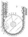
- the conveyor device shown in Figure 1 is suitable to ensure the transport of fruit or vegetables and allow, according to criteria of predetermined selection, a selective evacuation of said fruits or vegetables at the level of unloading zones arranged one after the other along the path of said conveying device.
- Such a conveying device is in particular designed to be integrated in a sorting unit as described in French patent FR-A-2,716,874, and constitute the second conveyor of this sorting unit ensuring the transport of fruit or vegetables between the loading and optical analysis area of the latter and the unloading areas, and along the path of a conveyor intermediary adapted to temporarily take care of fruit or vegetables to ensure their weighing.
- This conveyor device comprises, first of all, a endless chain 1 geared around two toothed wheels, only one of which, the wheel downstream tooth 2, is shown in Figure 1, each carried by a transverse shaft such as 3.
- This endless chain 1 is carried, at the level of the upper strand of the conveying device, by a horizontal longitudinal section 4 of section rectangular, made of polyethylene, forming a guide rail for said chain endless on which the rollers of the latter move.
- This guide rail 4 is itself carried by a profile in aluminum 6 provided for this purpose with a horizontal upper groove 5 in which the lower part of said guide rail is forcibly inserted.
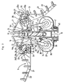
- the conveyor device comprises, secondly, a plurality of supports such as 7, 8 adapted to snap onto the chain without end 1, each carrying two conveying hands 9, 10 extending transversely from on either side of said supports, and articulated on the latter so as to be able rotate between a fruit and vegetable transport position and a tilted position evacuation of said fruit or vegetables at an unloading area.
- Each of these supports 7, 8 comprises first of all a upper wall in the form of a truncated dihedral consisting of two inclined sides 11, 12 transversely, extending on either side of a central longitudinal groove 13 focused on the longitudinal axis of the conveying device.
- each section 11, 12 has a double slope and comprises a first strip of width 11a, median, adjoining the groove 13, inclination less than that of a second strip of width 11b lateral.
- Each support 7, 8 further comprises a bottom wall 14 arranged to delimit, with the median strips 11a of the sides 11, 12 of the wall upper, a volume whose cross section has the general shape of a diamond.
- This bottom wall 14 has, for this purpose, two sides symmetrical inclined sides 14a, 14b connected by a horizontal central strip 14c.
- longitudinal struts such as 15 are formed between the upper walls 11, 12 and lower 14, and arranged so as to extend between the bottom of the groove 13 and the central strip 14c.
- Each support 7, 8 also has two walls vertical longitudinal 16a, 16b extending under the central strip 14c of the wall lower 14, and delimiting with the latter a yoke of width equivalent to that of the endless chain 1, capable of accommodating the latter, and of greater depth to the thickness of said endless chain.
- each vertical wall 17a, 17b has a notch 18 locking the links of the endless chain 1 inside the spaces longitudinal delimited by the walls 16a, 16b and said walls 17a, 17b.
- Each support 7, 8 also has two pairs of walls transverse such as 20 formed respectively on either side of the walls longitudinal 16a, 16b and delimited on the one hand by said longitudinal walls 16a, 16b and on the other hand by the lower walls 14 and upper 11, 12, so as to define two transverse slides such as 19, plumb with which, in addition, the side bands 11b of the sides 11, 12 of the upper wall have a notch.
- Each of the conveying hands 9, 10 made of a material with shape memory, such as polyacetal, has a bar central unit 21 having a concave shape longitudinally, on either side of which extend orthogonally a plurality of fingers such as 22, 23 arranged facing each other and curved upward to impart to said hand conveying the shape of an elongated bowl transversely to the endless chain 1, suitable for accommodating a fruit or vegetable.
- the central bar 21, of substantially constant width over its entire length is, moreover, seen laterally in elevation, and both on the other side of its inflection point, a first end section 21a thick constant, and a second section 21b of increasing thickness from said point inflection giving said second section, seen in elevation, the general shape of a right triangle whose base extends substantially horizontally in the transport position of the conveying hands 9, 10, and the hypotenuse of which forms the upper side for receiving fruit or vegetables.
- Each conveyor carrier arm 9, 10 further comprises, in the extension of the second section 21b of the center bar 21, a "body” 24 of articulation of said conveying hand to a support 7, 8, adapted to come s' insert into one of the transverse slides 19 of said support.
- This body further comprises a rear heel 26 projecting under the lower section 25b of the peripheral border 25.
- the rear section 25c of the peripheral edge 25 internally has a flat inclined ramp 29 for access to the notch 27, extending in the continuity of the curved portion of said rear section.
- This body 24 finally comprises an internal longitudinal sleeve 31 formed at the end of a deformable flexible blade 32 secured to the level of its other end, of the rear section 25c of the peripheral edge 25, and arranged so as to extend horizontally in the transport position of the conveying hands.
- This internal sleeve 31 constitutes a bearing housing the axis of longitudinal articulation 33 of the conveying hands 9, 10 which extends through orifices in the transverse walls 20 delimiting each slide 19 supports 7, 8.
- the conveying device also comprises means suitable for triggering the tilting of the conveying hands 9, 10 at the unloading zones.
- Each electromagnet 36 is, moreover, mounted on one of the lateral faces of the profile 6 by means of substantially semi-cylindrical rings 37 having, on the one hand, at their upper longitudinal edge a profile 38 of hooking on longitudinal ribs 39 which is provided with said profile and, on the other share, a flat bottom edge 40 bearing against the profile 6 making it possible to secure said ring on the latter by means of screws 41.
- the conveying device also comprises, at the level of the lower strand of the endless chain 1, a guide rail 42 and a profile 43 similar to guide rail 4 and profile 6, said guide rail having a width adapted to be housed in the central groove 13 of the supports 7, 8, so as to guide said supports without fatigue of the endless chain 1.
- This conveying device also includes means for resetting the conveying hands 9, 10 adapted to bring them to rotate from their tilted position to their locked position.
- These means of resetting consists of two polyethylene discs 47, 48 carried by the transverse shaft 3 of the downstream gear 2, on either side of the latter, of so as to be on the path of the conveying hands 9, 10 to bring these last to pivot to their transport position.
- the conveying device finally comprises two other polyethylene discs 44, 45 carried by the transverse shaft 3 of the downstream toothed wheel 2, and arranged between said toothed wheel and the reclosing disks 47, 48 of so as to be on the path of the heels 26 of the conveying hands 9, 10.
Landscapes
- Engineering & Computer Science (AREA)
- Mechanical Engineering (AREA)
- Chain Conveyers (AREA)
- Apparatuses For Bulk Treatment Of Fruits And Vegetables And Apparatuses For Preparing Feeds (AREA)
- Sorting Of Articles (AREA)
Claims (18)
- Vorrichtung zum Fördern von Produkten, insbesondere von Früchten, die so gestaltet ist, dass sie die genannten Produkte transportiert und sie an Entladezonen selektiv entlädt, wobei die Vorrichtung Folgendes umfasst:wobei die genannte Fördervorrichtung dadurch gekennzeichnet ist, dasseine Mehrzahl von Förderarmen (9, 10), die an Auflagen (7, 8) angelenkt sind, die von einer längsverlaufenden Endloskette (1) getragen werden, und die mit Mechanismen (27, 28) versehen sind, die die genannten Förderarme in einer Produkttransportposition halten;Auslösemittel (34-36), die so gestaltet sind, dass sie ein selektives Kippen der Förderarme (9, 10) zum Entladen der von diesen getragenen Produkte in einen der Entladebereiche bewirken;jeder Förderarm (9, 10) transversal von einem Hohlkörper (24) verlängert wird, der von einem Umfangsrand (25) begrenzt wird, innerhalb dessen eine Längshülse (31) verläuft, die eine einstückig mit der Auflage (7, 8) ausgebildete Längsgelenkachse (33) aufnimmt, wobei die genannte Hülse durch ein quer verlaufendes flexibles Element (32), das sich aufgrund einer Kraft zum Heben des Förderarms (9, 10) verformen kann und in seiner Produkttransportposition angeordnet ist, mit dem Umfangsrand (25) verbunden ist; unddie Mechanismen zum Halten der Förderarme (9, 10) in ihrer Produkttransportposition eine Aussparung (27) aufweisen, die in dem Körper (24) des genannten Förderarms vorgesehen ist, und einen Längsbolzen (28), der in die Auflage (7, 8) integriert und so angeordnet ist, dass er in der Aussparung (27) in der Transportposition der Förderarme (9, 10) aufgenommen werden kann, wobei die genannte Aussparung so angeordnet ist, dass sie den Bolzen (28) bei einer Verformung des flexiblen Mechanismus (32) freigibt, die durch eine Hebekraft der genannten Förderarme entsteht.
- Fördervorrichtung nach Anspruch 1, dadurch gekennzeichnet, dass der flexible Mechanismus der Förderarme (9, 10) aus einer flexiblen Lamelle (32) besteht, die so gestaltet ist, dass sie horizontal in der Transportposition der genannten Förderarme verläuft.
- Fördervorrichtung nach Anspruch 1 oder 2, dadurch gekennzeichnet, dass die Aussparung (27) im Umfangsrand (25) des Körpers (24) auf der Innenseite des genannten Körpers in einem Abschnitt des genannten Umfangsrandes im oberen Teil des Körpers (24) in der Transportposition der Förderarme (9, 10) vorgesehen ist.
- Fördervorrichtung nach Anspruch 3, dadurch gekennzeichnet, dass der Umfangsrand (25) des Körpers (24) der Förderarme (9, 10) eine geneigte ebene Zugangsrampe (30) zu der Aussparung (27) aufweist.
- Fördervorrichtung nach einem der vorherigen Ansprüche, dadurch gekennzeichnet, dass die Auslösemittel Folgendes umfassen:für jeden Förderarm (9, 10) einen unteren Auswurfansatz (26), der unter dem Körper (24) des genannten Förderarms vorsteht; undin jedem Entladebereich eine Nocke (34), die mit Schwenkmitteln (36) verbunden ist, die ein Kippen der Nocke um eine Längsachse zwischen einer aktiven Position, in der sie sich im Weg der Auswurfansätze (26) der Förderarme (9, 10) befindet und eine Aufwärtsverschiebung der genannten Auswurfansätze und ein anfängliches Kippen der genannten Förderarme erzeugt, und einer passiven Position bewirken können, in der die genannte Nocke die Passage des Auswurfansatzes (26) zulässt.
- Fördervorrichtung nach einem der vorherigen Ansprüche, bei der die Förderarme (9, 10) einen mittleren, transversal zur Endloskette (1) verlaufenden Stab (21) und eine Mehrzahl von Zinken (22, 23) umfassen, die orthogonal angeordnet und auf beiden Seiten des genannten mittleren Stabs verteilt sind, wobei die genannte Fördervorrichtung dadurch gekennzeichnet ist, dass der Körper (24) der genannten Förderarme in der Verlängerung des mittleren Stabs (21) verläuft und im Wesentlichen dieselbe Breite hat wie dieser.
- Fördervorrichtung nach Anspruch 6, dadurch gekennzeichnet, dass jede Auflage (7, 8) für jeden Förderarm (9, 10) eine Querschiene (19) umfasst, die den Körper (24) des genannten Förderarms aufnehmen und gleichzeitig ein Kippen desselben zulassen kann.
- Fördervorrichtung nach einem der vorherigen Ansprüche, dadurch gekennzeichnet, dassdie Endloskette (1) auf einer Führungsschiene (4) geführt wird, die mit einer Rollfläche für die genannte Endloskette versehen ist und von einem profilierten Längsabschnitt (16) getragen wird; undjede Auflage (7, 8) eine Abdeckung (16a, 16b) umfasst, die so gestaltet ist, dass sie die Endloskette (1) aufnimmt, und die mit Mitteln (17a, 17b, 18) zum Verriegeln der genannten Auflage auf der Endloskette versehen ist.
- Fördervorrichtung nach Anspruch 8, dadurch gekennzeichnet, dass die Mittel zum Verriegeln der Auflagen (7, 8) eine zweite Abdeckung (17a, 17b) umfassen, die einwärts von der ersten Abdeckung (16a, 16b) angeordnet und so dimensioniert ist, dass sie die Führungsschiene (4) verdeckt und innerhalb der genannten ersten Abdeckung zwei laterale Längsräume zum Aufnehmen der Glieder der Endloskette (1) begrenzt.
- Fördervorrichtung nach Anspruch 9, dadurch gekennzeichnet, dass die zweite Abdeckung (17a, 17b) äußere Rasten (18) zum Verriegeln der Endloskette (1) in den Längsräumen umfasst, die von der genannten zweiten Abdeckung begrenzt werden.
- Fördervorrichtung nach einem der Ansprüche 8 bis 10, dadurch gekennzeichnet, dass jede Auflage (7, 8) zwei Förderarme (9, 10) trägt, die transversal auf beiden Seiten der genannten Auflage verlaufen.
- Fördervorrichtung nach Anspruch 11, dadurch gekennzeichnet, dass jede Auflage (7, 8) auf beiden Seiten der Abdeckung (16a, 16b) Querwände (20) aufweist, die die Gelenkachsen (33) der Förderarme (9, 10) tragen.
- Fördervorrichtung nach Anspruch 7 und 12 gemeinsam, dadurch gekennzeichnet, dass jede Auflage (7, 8) auf jeder Seite der Abdeckung (16a, 16b) zwei Querwände (20) umfasst, die eine Schiene (19) für den Förderarm (9, 10) begrenzen.
- Fördervorrichtung nach Anspruch 11 oder 12, dadurch gekennzeichnet, dass jede Auflage (7, 8) eine obere Wand (11, 12) in der allgemeinen Form eines umgekehrten V umfasst, die von zwei transversal geneigten Flächen gebildet wird.
- Fördervorrichtung nach Anspruch 14, dadurch gekennzeichnet, dass die obere Wand (11, 12) jeder Auflage (7, 8) eine axiale Längsrille (13) umfasst, wobei die genannte Fördervorrichtung eine Längsführungsschiene (42) umfasst, die unter dem unteren Rand der Endloskette (1) verläuft und so gestaltet ist, dass sie in der genannten Rille der Auflagen aufgenommen wird.
- Fördervorrichtung nach Anspruch 6 und 8 gemeinsam, dadurch gekennzeichnet, dass die Mittel zum Schwenken der Nocken (34) einen Elektromagnet (36) umfassen, der mit einem Ring (37), der mit Mitteln (14) zum lösbaren Befestigen an dem genannten Profilabschnitt versehen ist, am Längsprofilabschnitt (6) befestigt ist.
- Fördervorrichtung nach einem der vorherigen Ansprüche, die zwei Zahnräder (2), oberhalb und unterhalb, für den Eingriff in die Endloskette (1) umfasst, dadurch gekennzeichnet, dass sie für jede Förderlinie eine Neueingriffsscheibe (47, 48) umfasst, die von der Querwelle (3) des nachgeschalteten Zahnrades (2) gelagert wird, und so angeordnet ist, dass sie auf dem Pfad der Förderarme (9, 10) verläuft.
- Fördervorrichtung nach Anspruch 5 und 17 gemeinsam, dadurch gekennzeichnet, dass sie für jede Förderlinie eine Scheibe (44, 45) umfasst, die mit einem peripheren Schaumstoffstreifen (46) verstehen ist, der von der Querwelle (3) des nachgeschalteten Zahnrades (2) getragen wird und so angeordnet ist, dass er sich auf dem Pfad der Auswurfansätze (26) der Förderarme (9, 10) befindet.
Applications Claiming Priority (2)
| Application Number | Priority Date | Filing Date | Title |
|---|---|---|---|
| FR9814278A FR2785892B1 (fr) | 1998-11-13 | 1998-11-13 | Dispositif de convoyage de produits, notamment de fruits |
| FR9814278 | 1998-11-13 |
Publications (2)
| Publication Number | Publication Date |
|---|---|
| EP1000883A1 EP1000883A1 (de) | 2000-05-17 |
| EP1000883B1 true EP1000883B1 (de) | 2004-09-08 |
Family
ID=9532696
Family Applications (1)
| Application Number | Title | Priority Date | Filing Date |
|---|---|---|---|
| EP99390021A Expired - Lifetime EP1000883B1 (de) | 1998-11-13 | 1999-10-22 | Fördervorrichtung für Produkte, insbesondere Früchte |
Country Status (8)
| Country | Link |
|---|---|
| US (1) | US6234297B1 (de) |
| EP (1) | EP1000883B1 (de) |
| AT (1) | ATE275521T1 (de) |
| DE (1) | DE69919960T2 (de) |
| ES (1) | ES2229636T3 (de) |
| FR (1) | FR2785892B1 (de) |
| NZ (1) | NZ500781A (de) |
| PT (1) | PT1000883E (de) |
Families Citing this family (18)
| Publication number | Priority date | Publication date | Assignee | Title |
|---|---|---|---|---|
| AUPS319602A0 (en) * | 2002-06-26 | 2002-07-18 | Colour Vision Systems Pty Ltd | Fruit handling equipment |
| NL2003516C2 (nl) * | 2009-09-21 | 2011-03-22 | Greefs Wagen Carrosserie | Transportinrichting voor het transporteren van een product, en sorteerinrichting en werkwijze daarvoor. |
| FR2963611B1 (fr) * | 2010-08-03 | 2013-12-06 | Maf Agrobotic | Dispositif de convoyage d'objets tels que des fruits ou legumes, a positions de dechargement ajustables |
| FR2966754B1 (fr) | 2010-10-29 | 2013-01-11 | Maf Agrobotic | Dispositif de groupage en lots d'objets flottants a poussoir motorise de superposition des objets. |
| EP2484593A1 (de) | 2011-02-04 | 2012-08-08 | Cabinplant International A/S | Vorrichtung zur Förderung und selektiven Entladung von Produkten |
| ITMO20120158A1 (it) * | 2012-06-19 | 2013-12-20 | Charlotte Anna Maria Liedl | Apparecchiatura per la selezione di prodotti agricoli. |
| DK3260401T3 (en) | 2012-09-06 | 2019-04-08 | Compac Tech Limited | VIPPE ACTUATOR AND TRANSPORTER SYSTEM |
| FR2999550B1 (fr) | 2012-12-14 | 2015-01-16 | Maf Agrobotic | Procede et dispositif de groupage en lots d'objets flottants avec superposition hydraulique des objets |
| US10011440B2 (en) | 2013-09-04 | 2018-07-03 | Compac Technologies Limited | Tipping actuator for a conveyor system |
| DE102014206740A1 (de) * | 2014-04-08 | 2015-10-08 | Siemens Aktiengesellschaft | Transportelement für einen Verteilförderer eines Sorters einer Sortieranlage |
| FR3035087B1 (fr) * | 2015-04-17 | 2017-04-21 | Maf Agrobotic | Dispositif de transport d'objets et dispositif de convoyage et de pesee equipe de tels dispositifs de transport |
| FR3073509B1 (fr) | 2017-11-15 | 2022-04-08 | Maf Agrobotic | Dispositif de groupage en lots de fruits ou legumes a canaux d'accumulation dotes de passages de derivation |
| FR3075770B1 (fr) | 2017-12-22 | 2020-01-03 | Maf Agrobotic | Procede et dispositif de groupage en lots d'objets flottants avec superposition hydraulique dynamique des objets |
| US11267660B2 (en) | 2018-03-09 | 2022-03-08 | Engineering Innovation, Inc. | Package sorting machine |
| CN108325865B (zh) * | 2018-03-12 | 2024-03-19 | 浙江大学 | 用于果蔬分选的单链双托式果杯装置 |
| WO2020117874A1 (en) * | 2018-12-06 | 2020-06-11 | Tompkins International | Vehicle and material handler |
| CN109794418B (zh) * | 2019-02-28 | 2024-09-20 | 广东力生智能有限公司 | 翻盘式分拣机 |
| WO2020182298A1 (en) | 2019-03-12 | 2020-09-17 | Cabinplant A/S | A method of weighing and batching articles |
Family Cites Families (7)
| Publication number | Priority date | Publication date | Assignee | Title |
|---|---|---|---|---|
| US3848728A (en) * | 1973-02-01 | 1974-11-19 | Butz Eng Corp | Conveyor and sorting system |
| US4089404A (en) * | 1976-09-29 | 1978-05-16 | A-T-O, Inc. | Tilting tray apparatus |
| JPS5919577A (ja) * | 1982-07-22 | 1984-02-01 | 株式会社マキ製作所 | 果実そ菜類の選別方法と装置 |
| WO1993007972A1 (en) * | 1991-10-15 | 1993-04-29 | Colour Vision Systems Pty. Ltd. | Conveying system for foodstuffs |
| US5436269A (en) * | 1991-11-14 | 1995-07-25 | Sagami Chemical Research Center | Method for treating hepatitis |
| FR2714874B1 (fr) | 1994-01-11 | 1996-04-12 | Andre Fontas | Rampe pour faciliter l'accès des véhicules de transport. |
| FR2716874B1 (fr) * | 1994-03-03 | 1996-06-21 | Materiel Arboriculture | Dispositif de convoyage de produits, notamment de fruits, adapté pour effectuer un triage desdits produits en fonction de critères de sélection prédéterminés. |
-
1998
- 1998-11-13 FR FR9814278A patent/FR2785892B1/fr not_active Expired - Fee Related
-
1999
- 1999-10-22 EP EP99390021A patent/EP1000883B1/de not_active Expired - Lifetime
- 1999-10-22 DE DE69919960T patent/DE69919960T2/de not_active Expired - Lifetime
- 1999-10-22 AT AT99390021T patent/ATE275521T1/de active
- 1999-10-22 PT PT99390021T patent/PT1000883E/pt unknown
- 1999-10-22 ES ES99390021T patent/ES2229636T3/es not_active Expired - Lifetime
- 1999-11-03 NZ NZ500781A patent/NZ500781A/en not_active IP Right Cessation
- 1999-11-03 US US09/432,609 patent/US6234297B1/en not_active Expired - Lifetime
Also Published As
| Publication number | Publication date |
|---|---|
| FR2785892A1 (fr) | 2000-05-19 |
| DE69919960T2 (de) | 2005-09-22 |
| EP1000883A1 (de) | 2000-05-17 |
| US6234297B1 (en) | 2001-05-22 |
| DE69919960D1 (de) | 2004-10-14 |
| PT1000883E (pt) | 2004-12-31 |
| ES2229636T3 (es) | 2005-04-16 |
| NZ500781A (en) | 2001-06-29 |
| ATE275521T1 (de) | 2004-09-15 |
| FR2785892B1 (fr) | 2001-03-02 |
Similar Documents
| Publication | Publication Date | Title |
|---|---|---|
| EP1000883A1 (de) | Fördervorrichtung für Produkte, insbesondere Früchte | |
| EP0670276B1 (de) | Fördereinrichtung für Produkte, insbesondere für Früchte, geeignet zum Sortieren von diesen Produkten gemäss definierten Auswahlkriterien | |
| EP0491407B1 (de) | Fördereinrichtung für Produkte, insbesondere für Früchte, insbesondere geeignet zum Sortieren von diesen Produkten Gemäss definierten Auswahlkriterien | |
| EP1040058A1 (de) | Fördervorrichtung für produkte, insbesondere früchte, bestimmt für die zufuhr zu einer sortiervorrichtung solcher produkte | |
| FR2851207A1 (fr) | Structure de siege pivotant comportant une unite d'ancrage, notamment pour vehicule automobile | |
| EP0470922B1 (de) | Automatische Maschinen zur vertikalen Positionierung von Behältern | |
| EP2439155A1 (de) | Transportplatte und Anlage zur Erstellung von Lebensmitteln mit solchen Transportplatten | |
| CA2494426C (fr) | Convoyeur | |
| BE1026614A1 (fr) | Trancheuse et procédé pour découper des pains successifs | |
| FR2730711A1 (fr) | Dispositif d'alimentation d'une unite de tri de produits longiformes, tels que carottes, unite de tri comportant ce dernier, et dispositif de distribution et calibreuse de cette unite de tri. | |
| FR2927007A1 (fr) | Receptacle d'objet tel qu'un fruit pour un dispositif de calibrage, comprenant une cavite par 3 points hauts disposes en triangle | |
| EP2386103A1 (de) | Einrichtung zum lagern, backen und automatischen abgeben von auf teig basierenden produkten, insbesondere brot | |
| EP1867589A1 (de) | Haltevorrichtung zur Gewichtseichung von Gegenständen wie Obst und Gemüse | |
| FR2700523A1 (fr) | Trémie pour charger des granulats. | |
| EP3345475A1 (de) | Mischbehälter mit seitenentladevorrichtung | |
| FR2872121A1 (fr) | Chariot porte-conteneur | |
| FR2585329A1 (fr) | Machine pour la mise en place automatique de produits dans des alveoles recepteurs | |
| FR2829477A1 (fr) | Dispositif automatique de vidage en continu de caisses ou analogue | |
| EP0456650B1 (de) | Vorrichtung zum fördern von schüttgut mit hin- und herbewegung | |
| FR2935368A1 (fr) | Dispositif a coupelle | |
| FR2687533A1 (fr) | Dispositif de preparation de sol pour en retirer des objets. | |
| EP1603383A1 (de) | Vorrichtung zum befüllen einer schachtel oder dergleichen | |
| FR2777809A1 (fr) | Dispositif de convoyage de produits, notamment de fruits ou legumes, adapte pour effectuer un triage des produits au moins en fonction de leurs poids | |
| EP4339021A1 (de) | Vorrichtung zum sichern von lasten, insbesondere futterballen, auf einem lastentransportfahrzeug, und lastentransportfahrzeug mit mindestens einer solchen vorrichtung | |
| FR2523526A1 (fr) | Dispositif de reglage de l'inclinaison de l'assise d'un siege de vehicule automobile |
Legal Events
| Date | Code | Title | Description |
|---|---|---|---|
| PUAI | Public reference made under article 153(3) epc to a published international application that has entered the european phase |
Free format text: ORIGINAL CODE: 0009012 |
|
| AK | Designated contracting states |
Kind code of ref document: A1 Designated state(s): AT BE CH CY DE DK ES FI FR GB GR IE IT LI LU MC NL PT SE |
|
| AX | Request for extension of the european patent |
Free format text: AL;LT;LV;MK;RO;SI |
|
| 17P | Request for examination filed |
Effective date: 20000927 |
|
| AKX | Designation fees paid |
Free format text: AT BE CH CY DE DK ES FI FR GB GR IE IT LI LU MC NL PT SE |
|
| GRAH | Despatch of communication of intention to grant a patent |
Free format text: ORIGINAL CODE: EPIDOS IGRA |
|
| GRAS | Grant fee paid |
Free format text: ORIGINAL CODE: EPIDOSNIGR3 |
|
| RAP1 | Party data changed (applicant data changed or rights of an application transferred) |
Owner name: MATERIEL POUR L' ARBORICULTURE FRUITIERE |
|
| GRAA | (expected) grant |
Free format text: ORIGINAL CODE: 0009210 |
|
| AK | Designated contracting states |
Kind code of ref document: B1 Designated state(s): AT BE CH CY DE DK ES FI FR GB GR IE IT LI LU MC NL PT SE |
|
| PG25 | Lapsed in a contracting state [announced via postgrant information from national office to epo] |
Ref country code: IE Free format text: LAPSE BECAUSE OF FAILURE TO SUBMIT A TRANSLATION OF THE DESCRIPTION OR TO PAY THE FEE WITHIN THE PRESCRIBED TIME-LIMIT Effective date: 20040908 Ref country code: FI Free format text: LAPSE BECAUSE OF FAILURE TO SUBMIT A TRANSLATION OF THE DESCRIPTION OR TO PAY THE FEE WITHIN THE PRESCRIBED TIME-LIMIT Effective date: 20040908 Ref country code: CY Free format text: LAPSE BECAUSE OF FAILURE TO SUBMIT A TRANSLATION OF THE DESCRIPTION OR TO PAY THE FEE WITHIN THE PRESCRIBED TIME-LIMIT Effective date: 20040908 |
|
| REG | Reference to a national code |
Ref country code: GB Ref legal event code: FG4D Free format text: NOT ENGLISH |
|
| REG | Reference to a national code |
Ref country code: CH Ref legal event code: EP |
|
| REG | Reference to a national code |
Ref country code: IE Ref legal event code: FG4D Free format text: FRENCH |
|
| REF | Corresponds to: |
Ref document number: 69919960 Country of ref document: DE Date of ref document: 20041014 Kind code of ref document: P |
|
| PG25 | Lapsed in a contracting state [announced via postgrant information from national office to epo] |
Ref country code: LU Free format text: LAPSE BECAUSE OF NON-PAYMENT OF DUE FEES Effective date: 20041022 |
|
| PG25 | Lapsed in a contracting state [announced via postgrant information from national office to epo] |
Ref country code: MC Free format text: LAPSE BECAUSE OF NON-PAYMENT OF DUE FEES Effective date: 20041031 Ref country code: LI Free format text: LAPSE BECAUSE OF NON-PAYMENT OF DUE FEES Effective date: 20041031 Ref country code: CH Free format text: LAPSE BECAUSE OF NON-PAYMENT OF DUE FEES Effective date: 20041031 |
|
| PG25 | Lapsed in a contracting state [announced via postgrant information from national office to epo] |
Ref country code: SE Free format text: LAPSE BECAUSE OF FAILURE TO SUBMIT A TRANSLATION OF THE DESCRIPTION OR TO PAY THE FEE WITHIN THE PRESCRIBED TIME-LIMIT Effective date: 20041208 Ref country code: DK Free format text: LAPSE BECAUSE OF FAILURE TO SUBMIT A TRANSLATION OF THE DESCRIPTION OR TO PAY THE FEE WITHIN THE PRESCRIBED TIME-LIMIT Effective date: 20041208 |
|
| REG | Reference to a national code |
Ref country code: PT Ref legal event code: SC4A Free format text: AVAILABILITY OF NATIONAL TRANSLATION Effective date: 20041102 |
|
| GBT | Gb: translation of ep patent filed (gb section 77(6)(a)/1977) | ||
| REG | Reference to a national code |
Ref country code: GR Ref legal event code: EP Ref document number: 20040404120 Country of ref document: GR |
|
| REG | Reference to a national code |
Ref country code: ES Ref legal event code: FG2A Ref document number: 2229636 Country of ref document: ES Kind code of ref document: T3 |
|
| REG | Reference to a national code |
Ref country code: IE Ref legal event code: FD4D |
|
| REG | Reference to a national code |
Ref country code: CH Ref legal event code: PL |
|
| PLBE | No opposition filed within time limit |
Free format text: ORIGINAL CODE: 0009261 |
|
| STAA | Information on the status of an ep patent application or granted ep patent |
Free format text: STATUS: NO OPPOSITION FILED WITHIN TIME LIMIT |
|
| 26N | No opposition filed |
Effective date: 20050609 |
|
| REG | Reference to a national code |
Ref country code: PT Ref legal event code: NF4A Free format text: RESTITUTIO IN INTEGRUM Effective date: 20120423 |
|
| PG25 | Lapsed in a contracting state [announced via postgrant information from national office to epo] |
Ref country code: IT Free format text: LAPSE BECAUSE OF NON-PAYMENT OF DUE FEES Effective date: 20111022 Ref country code: PT Free format text: LAPSE BECAUSE OF NON-PAYMENT OF DUE FEES Effective date: 20120423 |
|
| PGRI | Patent reinstated in contracting state [announced from national office to epo] |
Ref country code: IT Effective date: 20130308 |
|
| PGFP | Annual fee paid to national office [announced via postgrant information from national office to epo] |
Ref country code: GR Payment date: 20140826 Year of fee payment: 16 |
|
| PGFP | Annual fee paid to national office [announced via postgrant information from national office to epo] |
Ref country code: BE Payment date: 20140901 Year of fee payment: 16 |
|
| REG | Reference to a national code |
Ref country code: FR Ref legal event code: PLFP Year of fee payment: 17 |
|
| REG | Reference to a national code |
Ref country code: GR Ref legal event code: ML Ref document number: 20040404120 Country of ref document: GR Effective date: 20160506 |
|
| PG25 | Lapsed in a contracting state [announced via postgrant information from national office to epo] |
Ref country code: GR Free format text: LAPSE BECAUSE OF NON-PAYMENT OF DUE FEES Effective date: 20160506 |
|
| REG | Reference to a national code |
Ref country code: FR Ref legal event code: PLFP Year of fee payment: 18 |
|
| PGFP | Annual fee paid to national office [announced via postgrant information from national office to epo] |
Ref country code: GB Payment date: 20161019 Year of fee payment: 18 Ref country code: DE Payment date: 20161115 Year of fee payment: 18 |
|
| PGFP | Annual fee paid to national office [announced via postgrant information from national office to epo] |
Ref country code: AT Payment date: 20161010 Year of fee payment: 18 |
|
| PG25 | Lapsed in a contracting state [announced via postgrant information from national office to epo] |
Ref country code: BE Free format text: LAPSE BECAUSE OF NON-PAYMENT OF DUE FEES Effective date: 20151031 |
|
| REG | Reference to a national code |
Ref country code: FR Ref legal event code: PLFP Year of fee payment: 19 |
|
| REG | Reference to a national code |
Ref country code: DE Ref legal event code: R119 Ref document number: 69919960 Country of ref document: DE |
|
| REG | Reference to a national code |
Ref country code: AT Ref legal event code: MM01 Ref document number: 275521 Country of ref document: AT Kind code of ref document: T Effective date: 20171022 |
|
| GBPC | Gb: european patent ceased through non-payment of renewal fee |
Effective date: 20171022 |
|
| PG25 | Lapsed in a contracting state [announced via postgrant information from national office to epo] |
Ref country code: DE Free format text: LAPSE BECAUSE OF NON-PAYMENT OF DUE FEES Effective date: 20180501 Ref country code: GB Free format text: LAPSE BECAUSE OF NON-PAYMENT OF DUE FEES Effective date: 20171022 |
|
| PG25 | Lapsed in a contracting state [announced via postgrant information from national office to epo] |
Ref country code: AT Free format text: LAPSE BECAUSE OF NON-PAYMENT OF DUE FEES Effective date: 20171022 |
|
| REG | Reference to a national code |
Ref country code: FR Ref legal event code: PLFP Year of fee payment: 20 |
|
| PGFP | Annual fee paid to national office [announced via postgrant information from national office to epo] |
Ref country code: NL Payment date: 20181019 Year of fee payment: 20 |
|
| PGFP | Annual fee paid to national office [announced via postgrant information from national office to epo] |
Ref country code: PT Payment date: 20181015 Year of fee payment: 20 |
|
| PGFP | Annual fee paid to national office [announced via postgrant information from national office to epo] |
Ref country code: ES Payment date: 20181123 Year of fee payment: 20 Ref country code: FR Payment date: 20181022 Year of fee payment: 20 Ref country code: IT Payment date: 20181024 Year of fee payment: 20 |
|
| REG | Reference to a national code |
Ref country code: NL Ref legal event code: MK Effective date: 20191021 |
|
| PG25 | Lapsed in a contracting state [announced via postgrant information from national office to epo] |
Ref country code: PT Free format text: LAPSE BECAUSE OF EXPIRATION OF PROTECTION Effective date: 20191104 |
|
| REG | Reference to a national code |
Ref country code: ES Ref legal event code: FD2A Effective date: 20200721 |
|
| PG25 | Lapsed in a contracting state [announced via postgrant information from national office to epo] |
Ref country code: ES Free format text: LAPSE BECAUSE OF EXPIRATION OF PROTECTION Effective date: 20191023 |