EP1001080A2 - Section de formage - Google Patents
Section de formage Download PDFInfo
- Publication number
- EP1001080A2 EP1001080A2 EP99112925A EP99112925A EP1001080A2 EP 1001080 A2 EP1001080 A2 EP 1001080A2 EP 99112925 A EP99112925 A EP 99112925A EP 99112925 A EP99112925 A EP 99112925A EP 1001080 A2 EP1001080 A2 EP 1001080A2
- Authority
- EP
- European Patent Office
- Prior art keywords
- support
- formation system
- sheet formation
- nozzle
- deflection
- Prior art date
- Legal status (The legal status is an assumption and is not a legal conclusion. Google has not performed a legal analysis and makes no representation as to the accuracy of the status listed.)
- Withdrawn
Links
Images


Classifications
-
- D—TEXTILES; PAPER
- D21—PAPER-MAKING; PRODUCTION OF CELLULOSE
- D21F—PAPER-MAKING MACHINES; METHODS OF PRODUCING PAPER THEREON
- D21F1/00—Wet end of machines for making continuous webs of paper
- D21F1/02—Head boxes of Fourdrinier machines
-
- D—TEXTILES; PAPER
- D21—PAPER-MAKING; PRODUCTION OF CELLULOSE
- D21F—PAPER-MAKING MACHINES; METHODS OF PRODUCING PAPER THEREON
- D21F1/00—Wet end of machines for making continuous webs of paper
- D21F1/02—Head boxes of Fourdrinier machines
- D21F1/028—Details of the nozzle section
-
- D—TEXTILES; PAPER
- D21—PAPER-MAKING; PRODUCTION OF CELLULOSE
- D21G—CALENDERS; ACCESSORIES FOR PAPER-MAKING MACHINES
- D21G9/00—Other accessories for paper-making machines
- D21G9/0009—Paper-making control systems
Definitions
- the invention relates to a sheet formation system of a paper or Board machine with a headbox with a Headbox nozzle consisting of two arranged on the side Nozzle side shields and a first and a second, machine-wide nozzle wall is formed, continue with two in the area of the headbox nozzle converging seven and with at least two Deflection devices, which the sieves in the area of Guide the headbox nozzle over a deflection surface.
- Such a sheet formation system is for example from the the preamble forming US Pat. No. 4,358,342 known.
- This patent shows the beginning of a Sheet forming system of a paper machine with one Twin wire former in the area of the headbox nozzle and Inlet gusset of two screens.
- the headbox nozzle has Outlet area via sectionally adjustable headbox lips, whereby the basis weight cross profile of the formed Paper web are influenced or made more uniform should.
- the top and bottom walls of the headbox nozzle itself is here through a constructively massive construction in their Geometry kept constant. For hiring the deformable upper or lower lip of the Headbox supports the respective lip on the massive Basic body of the upper nozzle wall or lower nozzle wall from.
- German patent DE 41 05 215 C2 pointed out.
- This patent also uses a Sheet formation system in the area of the inlet gusset Twin-wire section disclosed.
- the peculiarity of this Sheet formation system is that the two rollers, which form the inlet gusset of the twin wire section, are stored hydrostatically. Due to the machine width hydrostatic bearing is possible To compensate for the deflection of the rollers and thereby despite small roller diameter the inlet geometry of the gusset very evenly across the entire width of the paper machine hold.
- the inventors propose the known Sheet formation system of a paper or board machine with a headbox with a headbox nozzle consisting of two laterally arranged nozzle side shields and a first one and a second machine-wide nozzle wall is formed, continue with two in the field of Headbox converging sieves and with at least two deflection devices, which the sieves in the area of Guide the headbox nozzle over a deflection surface, to develop further in that at least a support device with at least one support element for at least part of a nozzle wall against at least one Deflection surface is provided.
- At least one the deflection surfaces a roller surface and / or the Be the surface of a sliding shoe.
- Sheet formation system is designed such that at least one of the deflection devices a forming roller or Has breast roll.
- the support elements of the support device can be used as a roller or as a shoe that glides over the roller surface or rolls. Besides, can according to the invention also at least one of the support elements at least one hydrostatic bearing respectively Have support.
- the support device has at least one pressure chamber towards the nozzle wall.
- a further advantageous embodiment of this sectioned support device provides this with means for section-wise regulation or control of the The intensity of the support.
- Control valves individual pressure chambers of the segments of the Activate the support device individually and in this way generate a cross profile control.
- the support device according to the invention can also via a variety of support elements (for example in the form of individual spindles or hydraulic rams), the support effect may be individually adjusted can be.
- Another advantageous embodiment of the sheet formation system can be that at least one of the Deflection devices adjustable in terms of their deflection is executed, that is to say via a roller known per se - Deflection compensation device has.
- the Inventor also proposed the sheet formation system according to the Preamble of claim 1 or according to one of the other To improve the inventive designs in that it in the area of at least one nozzle wall with at least one Support table with at least one pressure generating device between the support table and the nozzle wall.
- An advantageous design of this sheet formation system can consist in that the pressure generating device has at least one pressure chamber, the at least a pressure chamber between the support table and the nozzle wall in Transverse direction can be performed segmented. Through this The pressure chamber segments can be segmented with different pressures are applied and thus a Create the desired pressure cross profile.
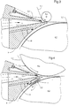
- FIG. 1 shows a sheet formation system according to the invention in the area of the inlet gusset of a twin-wire paper machine in longitudinal section.
- the headbox has one Headbox nozzle 1, which consists of two not visible here, laterally arranged nozzle side shields and a first one and a second machine-wide nozzle wall 2.1 and 2.2 exists.
- the headbox nozzle 1 thus formed is sufficient with its nozzle outlet gap in the gusset of the wire section inside.
- the gusset is on the top by the Deflection device 4.1 - which is designed here as a deflection roller and carries the sieve 3.1 - and through the one below Deflection device 4.2 - which is designed here as a forming roller and which carries the sieve 3.2 - formed.
- the second nozzle wall 2.2 below in this example is supported by a support device against the rotating Deflection surface 5.2 of the deflection device 4.2 supported.
- the support device consists of a support element 6, which on the nozzle wall side hydrostatically via a Pressure chamber 7 is mounted.
- a pressure pad 8 is provided with which the support element 6 via hydraulic cushion opposite the Deflecting surface 5.2 can support, between Support element 6 and the deflecting surface of the sieve 3.2 runs.
- liquid into the pressure pad 8 through channels can be supplied via the support element 6, or it can be in Direction of rotation in front of the support element enough liquid the sieve to be abandoned, so that there is a collecting the appropriate amount of liquid and the builds up necessary back pressure.
- FIG. 2 shows a sheet formation system similar to that of FIG 1.
- the support element 6 is here not as a static shoe, but as a roller.
- the storage of the roller can be both hydrostatic and also hydrodynamic - via appropriately designed Pressure pad - done. Will this hydraulic support compared to the nozzle wall 2.2 over the machine width sectioned, there is also a possibility for Influencing the geometry of the headbox in the area of Outlet gap.
- Figure 3 shows another way of support the nozzle wall of a headbox.
- longitudinal section is - according to Figures 1 and 2 - a headbox 1 in Recognize the gusset of a twin wire former.
- the lower one or second nozzle wall 2.2 points in the rear make an incision in cooperation with one underlying support table 9 forms a pressure chamber 10.
- the support table 9 is solid and takes the Compressive forces that arise within the pressure chamber 10 over the machine width, with a certain in this area Deflection can occur while the overlying relatively thin-walled nozzle wall 2.2 due to the uniform Pressure ratios - despite the back pressure from the nozzle area - does not experience a bend.
- Figure 4 shows a combination of the invention Execution of the sheet formation system from FIG. 1 with a hydrostatic support shoe 6 in the front area of the second Nozzle wall 2.2 of the headbox nozzle 1 and another Supporting the rear area of the second nozzle wall 2.2 with the help of a support table 9, which in cooperation with the second nozzle wall 2.2 forms a pressure chamber 10.
- FIG. 5 shows an embodiment similar to that of FIG. 4, however, the support shoe in the front area is the Headbox nozzle 1 replaced by a support roller.
- the first deflection device 4.1 in the form of a Profilable deflection roller shown, which over a has hydraulic support 11, and thus on Machine width is profiled.
Landscapes
- Paper (AREA)
Applications Claiming Priority (2)
| Application Number | Priority Date | Filing Date | Title |
|---|---|---|---|
| DE19852634 | 1998-11-14 | ||
| DE19852634A DE19852634A1 (de) | 1998-11-14 | 1998-11-14 | Blattbildungssystem |
Publications (2)
| Publication Number | Publication Date |
|---|---|
| EP1001080A2 true EP1001080A2 (fr) | 2000-05-17 |
| EP1001080A3 EP1001080A3 (fr) | 2004-02-11 |
Family
ID=7887852
Family Applications (1)
| Application Number | Title | Priority Date | Filing Date |
|---|---|---|---|
| EP99112925A Withdrawn EP1001080A3 (fr) | 1998-11-14 | 1999-07-05 | Section de formage |
Country Status (3)
| Country | Link |
|---|---|
| US (1) | US6319363B1 (fr) |
| EP (1) | EP1001080A3 (fr) |
| DE (1) | DE19852634A1 (fr) |
Cited By (1)
| Publication number | Priority date | Publication date | Assignee | Title |
|---|---|---|---|---|
| WO2012003997A1 (fr) | 2010-07-09 | 2012-01-12 | Martin Vorbach | Dispositif et procédé de traitement de données |
Citations (1)
| Publication number | Priority date | Publication date | Assignee | Title |
|---|---|---|---|---|
| US5160583A (en) * | 1991-12-02 | 1992-11-03 | Beloit Corporation | Controlled jet injection apparatus for a papermaking machine headbox |
Family Cites Families (10)
| Publication number | Priority date | Publication date | Assignee | Title |
|---|---|---|---|---|
| USRE25333E (en) * | 1963-02-19 | Baxter | ||
| US3313681A (en) * | 1964-08-27 | 1967-04-11 | Beloit Corp | Headbox with bottom wall having controllable deflection |
| US3450596A (en) * | 1965-02-19 | 1969-06-17 | Black Clawson Co | Headbox for twin wire paper machine |
| US3855057A (en) * | 1967-11-02 | 1974-12-17 | Beloit Corp | Paper formation utilizing a large diameter suction roll |
| US3619362A (en) * | 1969-02-03 | 1971-11-09 | Beloit Corp | Papermaking headbox stock nozzle with liquid jacket means for elimination of stock exposure to air |
| US3734821A (en) * | 1970-12-14 | 1973-05-22 | Allis Chalmers Mfg Co | Headbox for cylinder roll papermaking machine |
| FI760291A7 (fr) * | 1976-02-06 | 1977-08-07 | Tampella Oy Ab | |
| US4358342A (en) * | 1981-01-19 | 1982-11-09 | Kimberly-Clark Corporation | Papermaking headbox having rigid lips and actvating means |
| DE3841860A1 (de) * | 1988-12-13 | 1990-06-21 | Escher Wyss Gmbh | Unterlippe am stoffauflauf einer papiermaschine |
| DE4105215C2 (de) * | 1991-02-20 | 1996-10-17 | Voith Gmbh J M | Sieb-Formerpartie |
-
1998
- 1998-11-14 DE DE19852634A patent/DE19852634A1/de not_active Withdrawn
-
1999
- 1999-07-05 EP EP99112925A patent/EP1001080A3/fr not_active Withdrawn
- 1999-11-09 US US09/436,498 patent/US6319363B1/en not_active Expired - Fee Related
Patent Citations (1)
| Publication number | Priority date | Publication date | Assignee | Title |
|---|---|---|---|---|
| US5160583A (en) * | 1991-12-02 | 1992-11-03 | Beloit Corporation | Controlled jet injection apparatus for a papermaking machine headbox |
Cited By (1)
| Publication number | Priority date | Publication date | Assignee | Title |
|---|---|---|---|---|
| WO2012003997A1 (fr) | 2010-07-09 | 2012-01-12 | Martin Vorbach | Dispositif et procédé de traitement de données |
Also Published As
| Publication number | Publication date |
|---|---|
| DE19852634A1 (de) | 2000-05-18 |
| US6319363B1 (en) | 2001-11-20 |
| EP1001080A3 (fr) | 2004-02-11 |
Similar Documents
| Publication | Publication Date | Title |
|---|---|---|
| DE3514554C2 (de) | Stoffauflauf-Vorrichtung für eine Papiermaschine und Verfahren zu deren Betrieb | |
| DE4420801C2 (de) | Verfahren zum Betreiben einer Doppelsiebzone einer Papiermaschine zur Herstellung von Faserstoffbahnen sowie Siebzone hierzu | |
| DE3628282A1 (de) | Stationaere stuetzvorrichtung | |
| DE3201635C2 (de) | Kalanderanordnung | |
| DE2454209A1 (de) | Verfahren und vorrichtung zum herstellen einer aus faserpartikeln gebildeten kontinuierlichen materialbahn | |
| EP1050622A2 (fr) | Dispositif et procédé d'application pour une machine à papier | |
| DE69422855T2 (de) | Verfahren, Vorrichtung und Regelanordnung in einer Papiermaschine, zum Steuern des Querprofiles einer Papierbahn | |
| DE60130629T2 (de) | Vielwalzen-Walzwerk | |
| DE2310445C3 (de) | Papiermaschine zur Herstellung von Mehrlagenpapier | |
| DE3808142A1 (de) | Lagereinrichtung | |
| DE3644454C1 (de) | Stoffauflauf fuer eine Papiermaschine od.dgl. | |
| EP1365067A1 (fr) | Section de formage | |
| EP1001080A2 (fr) | Section de formage | |
| EP0928843B1 (fr) | Dispositif de pressage | |
| AT406172B (de) | Vorrichtung zur zufuhr einer faserstoffsuspension auf eine entwässerungseinrichtung | |
| DE1761572A1 (de) | Kalander | |
| DE4326867C2 (de) | Siebpartie einer Maschine zur Herstellung von Faserstoffbahnen | |
| DE69311281T2 (de) | Verfahren und Vorrichtung in Beziehung zum Einlaufspalt im Formierteil einer Papiermaschine | |
| DE1461176A1 (de) | Stoffauflauf mit geschlossenem Auflaufkasten,insbesondere fuer Papiermaschinen | |
| DE69508136T2 (de) | Vorrichtung für die zonenweise Einstellung der Belastung in der Nasspartie einer Papier- oder Pappemaschine | |
| EP0997578A1 (fr) | Caisse de tête | |
| EP0831172A2 (fr) | Partie toile et procédé de déshydratation d'une bande fibreuse dans une partie toile | |
| DE274944C (fr) | ||
| DE1802004C (de) | Entwässerungsvorrichtung für Papiermaschinen | |
| DE602004005195T2 (de) | Verfahren und vorrichtung für doppelsiebpresse |
Legal Events
| Date | Code | Title | Description |
|---|---|---|---|
| PUAI | Public reference made under article 153(3) epc to a published international application that has entered the european phase |
Free format text: ORIGINAL CODE: 0009012 |
|
| AK | Designated contracting states |
Kind code of ref document: A2 Designated state(s): AT BE CH CY DE DK ES FI FR GB GR IE IT LI LU MC NL PT SE |
|
| AX | Request for extension of the european patent |
Free format text: AL;LT;LV;MK;RO;SI |
|
| RAP1 | Party data changed (applicant data changed or rights of an application transferred) |
Owner name: VOITH PAPER PATENT GMBH |
|
| PUAL | Search report despatched |
Free format text: ORIGINAL CODE: 0009013 |
|
| AK | Designated contracting states |
Kind code of ref document: A3 Designated state(s): AT BE CH CY DE DK ES FI FR GB GR IE IT LI LU MC NL PT SE |
|
| AX | Request for extension of the european patent |
Extension state: AL LT LV MK RO SI |
|
| 17P | Request for examination filed |
Effective date: 20040811 |
|
| AKX | Designation fees paid |
Designated state(s): AT DE FI SE |
|
| STAA | Information on the status of an ep patent application or granted ep patent |
Free format text: STATUS: THE APPLICATION IS DEEMED TO BE WITHDRAWN |
|
| 18D | Application deemed to be withdrawn |
Effective date: 20060204 |