EP1001099A2 - Elément d'installation - Google Patents
Elément d'installation Download PDFInfo
- Publication number
- EP1001099A2 EP1001099A2 EP99121367A EP99121367A EP1001099A2 EP 1001099 A2 EP1001099 A2 EP 1001099A2 EP 99121367 A EP99121367 A EP 99121367A EP 99121367 A EP99121367 A EP 99121367A EP 1001099 A2 EP1001099 A2 EP 1001099A2
- Authority
- EP
- European Patent Office
- Prior art keywords
- installation element
- vertical struts
- element according
- frame
- wall
- Prior art date
- Legal status (The legal status is an assumption and is not a legal conclusion. Google has not performed a legal analysis and makes no representation as to the accuracy of the status listed.)
- Granted
Links
- 238000009434 installation Methods 0.000 title claims abstract description 50
- 229910052602 gypsum Inorganic materials 0.000 claims description 7
- 239000010440 gypsum Substances 0.000 claims description 7
- 239000002184 metal Substances 0.000 claims description 7
- 238000004806 packaging method and process Methods 0.000 claims description 4
- 230000002787 reinforcement Effects 0.000 claims description 4
- 230000003014 reinforcing effect Effects 0.000 claims description 3
- 238000005553 drilling Methods 0.000 abstract description 2
- 238000000034 method Methods 0.000 description 4
- 229910000831 Steel Inorganic materials 0.000 description 3
- 239000010959 steel Substances 0.000 description 3
- 238000003466 welding Methods 0.000 description 3
- 238000005452 bending Methods 0.000 description 2
- 239000011094 fiberboard Substances 0.000 description 2
- 238000004519 manufacturing process Methods 0.000 description 2
- 238000004080 punching Methods 0.000 description 2
- 238000005253 cladding Methods 0.000 description 1
- 238000010276 construction Methods 0.000 description 1
- 239000004744 fabric Substances 0.000 description 1
- 238000011010 flushing procedure Methods 0.000 description 1
- 238000003780 insertion Methods 0.000 description 1
- 230000037431 insertion Effects 0.000 description 1
- 238000010079 rubber tapping Methods 0.000 description 1
- XLYOFNOQVPJJNP-UHFFFAOYSA-N water Substances O XLYOFNOQVPJJNP-UHFFFAOYSA-N 0.000 description 1
Images


Classifications
-
- E—FIXED CONSTRUCTIONS
- E03—WATER SUPPLY; SEWERAGE
- E03D—WATER-CLOSETS OR URINALS WITH FLUSHING DEVICES; FLUSHING VALVES THEREFOR
- E03D11/00—Other component parts of water-closets, e.g. noise-reducing means in the flushing system, flushing pipes mounted in the bowl, seals for the bowl outlet, devices preventing overflow of the bowl contents; devices forming a water seal in the bowl after flushing, devices eliminating obstructions in the bowl outlet or preventing backflow of water and excrements from the waterpipe
- E03D11/13—Parts or details of bowls; Special adaptations of pipe joints or couplings for use with bowls, e.g. provisions in bowl construction preventing backflow of waste-water from the bowl in the flushing pipe or cistern, provisions for a secondary flushing, for noise-reducing
- E03D11/14—Means for connecting the bowl to the wall, e.g. to a wall outlet
- E03D11/143—Mounting frames for toilets and urinals
Definitions
- the invention relates to an installation element for sanitary facilities with a frame of at least two, in essentially vertical struts formed from hollow profiles, the fasteners on the foot and head area have, and at least one of the vertical struts cross strut spaced from each other.
- Such an installation element is, for example known from EP 0 786 562 A1.
- a rectangular frame made of hollow profile tubes is provided, that by means of foot plates on the building floor stands and by means of two connecting parts mounted in the assembly frame, each with a fastener, that has to be attached to a building wall, at a distance is held to the building wall.
- the invention has for its object in the preamble of claim 1 specified installation element to improve and in particular to train so that it versatile and inexpensive to manufacture is.
- the vertical struts are formed from square tube, to which a sheet metal U-shaped head cross member is fastened in the head area as the first cross strut, with one in each of the U-legs facing the wall in the head cross bar at the two end areas Threaded bore is formed, in each of which a screw bolt of a wall mounting bracket can optionally be screwed.
- the threaded bores can be expediently reinforced by collar-shaped protuberances, the protuberances being possible, for example, when punching out the sheet metal blank and / or when bending the U-profile.
- reinforcement corners can also be integrally formed on the two U-legs in the area of the connection of the two vertical struts, so that the head traverse on the two vertical struts in the area of the two reinforcement corners by a weld seam on the side facing the wall or on the side of the planking opposite side is to be connected.
- plates can be arranged at the foot of the vertical struts, with which the installation element can be fastened to the floor of the building or optionally used in two different width rail profiles, the width of the plate being determinable with a flexible flap.
- the plates can also be expediently fastened to rods which can be fixed at different insertion depths in the vertical struts formed from square tube.
- the vertical struts can have fastening bores to which frame extensions made of L-profiles can be fastened.
- These widened frames primarily serve for easy planking of the installation element with a gypsum fibreboard.
- the L-profiles can be attached to the side surfaces of the cut gypsum fiber boards as reinforcement during transport, so that damage in transit is largely avoided.
- holes can be expediently provided on the two inner sides of the vertical struts, to which an adapter strip made of an L-profile can optionally be attached, with a raster in the form of a row of holes being formed on the leg projecting from the vertical strut, so that in each case required Heights a crossbar for the urinals or sinks etc. offered in the trade can be attached.
- at least one cross strut preferably made of square tube, can be expediently provided at a distance from the head traverse.
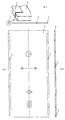
- the installation element is in this case formed by a frame 1, which is fastened to the foot area with plates 12 on the building floor and is held at the head area on the recessed building wall by wall fastening tabs 30 and screw bolts 3.
- the frame 1 here consists of a head traverse 2, on each of which a vertical strut 10, 11 is fastened, a cross strut 7 being arranged in the foot region.
- the vertical struts 10, 11 are made from square steel tubing, while the head cross member 2 is bent from 1.5 mm thick steel sheet to form a U-shaped profile, as can be seen in particular from FIGS. 3 and 4.
- the head traverse 2 is formed from a sheet steel blank shown in FIG.
- the head traverse thus produced in a U-shape has a U-leg 20 facing the wall and a U-leg 21 facing away from the wall, and the end faces are closed with end flaps 25.
- a threaded bore 201 is formed in a collar-shaped protuberance 202 on the U-leg 20 facing the wall, into which a screw bolt 3 of a wall fastening bracket 30 can be screwed, as can be seen in particular from FIG. 2 of the drawing .
- an access bore 203 with a larger diameter is provided coaxially with the threaded bore 201 in the U-leg 21 facing away from the wall.
- a protruding reinforcing corner 22 is formed on each of the two U-legs 20, 21 in the connection area to the two vertical struts 10, 11.
- the two vertical struts 10, 11 are thus butted against the reinforcing corners 22 of the U-legs 20, 21 and then permanently connected to each other on the side facing the building wall by a weld seam 23.
- the welding process can take place on both U-legs 20, 21, as can be seen from FIG. 4.
- the weld seams 23 are attached to the back or to the side facing the building wall, so that rework is not necessary.
- the welding process can be carried out inexpensively in a single welding position.
- the cross strut 7 is welded to the vertical struts 10, 11 at the opposite end region.
- rods 14 At the foot area of the vertical struts 10, 11 are rods 14 axially displaceable and inserted in the required Pull-out position with a clamping screw 15 fixable.
- the rods 14 are designed as a hollow profile and have a longitudinal slot 140 for the Reaching through the clamping screw 15.
- the end region of the rods 14 is a plate 12 in each case attached as a foot.
- the plate 12 has one of several connecting strips 120 held flexible the building wall side located flap 13, with the Screw connection, for example to the building floor, Openings 121 are formed, as is particularly the case 5 and 6 of the drawing can be seen.
- the cloth 13 is usually folded up by 90 °, like it can be seen from FIGS. 1 and 5 of the drawing. In Fig.
- the tab 13 in the plane of the Plate 12 bent downwards is the tab 13 in the plane of the Plate 12 bent downwards.
- the plate 12 is so dimensioned in two common, one different Wide floor rail profiles 8a, 8b can be used for lightweight walls or room dividers is.
- the base plate is 90 ° high curved tab 13 can be inserted into the bottom rail profile 8a, as shown in Fig. 5.
- you can the plate 12 also with the bottom rail profile 8b wider width can be used in that the rag 3 is bent down into the plane of the plate 12, as shown in Fig. 6 of the drawing.
- cross strut 7 Above the cross strut 7 is a profile bar Holder 9 between the two vertical struts 10 and 11 attached. There is also a higher one Cheek 90 on the inside of the frame of the vertical struts 10.11 provided. The holder 9 and the cheeks 90 serve here for the attachment of one in the drawing toilet body not shown and a water cistern.
- the installation element is clad in usually with a plasterboard.
- the plasterboard can widen the frame 1 required in the area of the vertical struts 10 and 11 his.
- a frame widening 4 is provided in the form of an L-profile, as can be seen from FIGS. 7 to 9.
- the respective frame widening 4 is in each case with the short leg on the outside of the frame 1 to the Vertical struts 10,11 fastened with self-tapping screws.
- a planking 5 e.g. with a Gypsum fibreboard, the installation element.
- the installation element can be used in the following ways: For a pre-wall installation, the screw bolts 3 with the wall fastening tabs 30 can be screwed into the two threaded holes 201 in the installation element, as can be seen from FIG. 2. After the two screw bolts 3 have been adjusted in length by the screwing-in process, each screw bolt 3 can be secured in the head traverse 2 with a lock nut 31. Then a height adjustment of the frame 1 can be carried out with the aid of the telescopically arranged rods 14, each of which can be secured with a clamping screw 15. The frame 1 can then be fastened to the two wall fastening straps 30 with dowel screws on the building wall and to the two floor panels 12 likewise with dowel screws on the building floor.
- the planking 5 can be attached to the frame 1 and the WC (not shown in the drawing) can be installed.
- the installation element with the frame 1 can also be fastened in a lightweight wall, in particular on stands with an open C-profile.
- the bolts 3 with the fastening tabs 30 are not required here.
- the frame 1 with the plates 12 can be set in a floor rail profile 8a, 8b.
- the two vertical struts 10, 11 of the frame 1 are screwed by means of self-drilling screws from the open side of the C-profile, so that a firm connection is made between the lightweight wall and the installation element.
- the installation element can optionally be inserted into the two common bottom rail profiles 8a or 8b which have a different width. All that is required is bending the flap 13 through 90 °.
- 10 and 11 is a slightly modified installation element shown for a urinal. Corresponding can run an installation element for a washbasin become.
- the head traverse 2 points here in the middle area a recess 24 on the U-legs 20,21 on.
- On the inside of the frame 1 is one Adapter strip 6 made of L-profile on holes 100 with the Vertical struts 10,11 attached.
- each time in the frame 1 extending leg of the adapter strip 6 is a row of holes as a grid 60 provided with the trusses 61 in different Height in the frame 1 can be attached.
- On the trusses 61 a urinal or washstand etc. can be attached become.
- a further traverse 62 with Sheet metal screws can be attached to the vertical struts 10 and 11. It serves to hold the flushing device a urinal not shown in the drawing. Otherwise, the installation element corresponds to that in 1 to 9 described embodiment.
Landscapes
- Health & Medical Sciences (AREA)
- Life Sciences & Earth Sciences (AREA)
- Engineering & Computer Science (AREA)
- Hydrology & Water Resources (AREA)
- Public Health (AREA)
- Water Supply & Treatment (AREA)
- Residential Or Office Buildings (AREA)
- Furniture Connections (AREA)
- Supports For Pipes And Cables (AREA)
- Refuge Islands, Traffic Blockers, Or Guard Fence (AREA)
- Mutual Connection Of Rods And Tubes (AREA)
- Analysing Materials By The Use Of Radiation (AREA)
- Finger-Pressure Massage (AREA)
Applications Claiming Priority (2)
| Application Number | Priority Date | Filing Date | Title |
|---|---|---|---|
| DE19851450A DE19851450A1 (de) | 1998-11-09 | 1998-11-09 | Installationselement |
| DE19851450 | 1998-11-09 |
Publications (3)
| Publication Number | Publication Date |
|---|---|
| EP1001099A2 true EP1001099A2 (fr) | 2000-05-17 |
| EP1001099A3 EP1001099A3 (fr) | 2001-04-18 |
| EP1001099B1 EP1001099B1 (fr) | 2006-04-05 |
Family
ID=7887070
Family Applications (1)
| Application Number | Title | Priority Date | Filing Date |
|---|---|---|---|
| EP99121367A Expired - Lifetime EP1001099B1 (fr) | 1998-11-09 | 1999-10-27 | Elément d'installation |
Country Status (3)
| Country | Link |
|---|---|
| EP (1) | EP1001099B1 (fr) |
| AT (1) | ATE322586T1 (fr) |
| DE (2) | DE19851450A1 (fr) |
Cited By (2)
| Publication number | Priority date | Publication date | Assignee | Title |
|---|---|---|---|---|
| EP1544364A1 (fr) * | 2003-12-17 | 2005-06-22 | Rainer Weghake | Revêtement pour cadre à monter |
| IT202200017712A1 (it) * | 2022-08-29 | 2024-02-29 | Carla Campiglia | Controtelaio di supporto per cassette di scarico per wc ad incasso |
Families Citing this family (1)
| Publication number | Priority date | Publication date | Assignee | Title |
|---|---|---|---|---|
| DE102007022019A1 (de) * | 2007-05-08 | 2008-11-13 | GROHEDAL Sanitärsysteme GmbH & Co. KG | Stützfuß für einen Sanitär-Installationsrahmen |
Citations (1)
| Publication number | Priority date | Publication date | Assignee | Title |
|---|---|---|---|---|
| EP0786562A1 (fr) | 1996-01-25 | 1997-07-30 | Geberit Technik Ag | Support mural sur un cadre de montage |
Family Cites Families (5)
| Publication number | Priority date | Publication date | Assignee | Title |
|---|---|---|---|---|
| DE3415585A1 (de) * | 1984-04-21 | 1985-10-24 | Norbert 3012 Langenhagen Ohmes | Installationswand fuer sanitaere objekte |
| CH668612A5 (fr) * | 1986-06-27 | 1989-01-13 | Hubert Rutsch | Structure porteuse modulaire pour installations sanitaires prefabriquees. |
| DE9412649U1 (de) * | 1994-08-05 | 1994-11-10 | Robert Plersch Edelstahl-Technik GmbH, 87749 Hawangen | Rahmen für die Vorwandmontage von sanitären Einrichtungen |
| DE19507766A1 (de) * | 1995-03-06 | 1996-09-12 | Rost & Co Gmbh | Auflagewinkel |
| DE29707090U1 (de) * | 1997-04-19 | 1997-08-28 | Schneider, Katharina, 56470 Bad Marienberg | Vorrichtung zur Wandmontage mindestens eines sanitären Gegenstandes |
-
1998
- 1998-11-09 DE DE19851450A patent/DE19851450A1/de not_active Withdrawn
-
1999
- 1999-10-27 DE DE59913300T patent/DE59913300D1/de not_active Expired - Lifetime
- 1999-10-27 AT AT99121367T patent/ATE322586T1/de not_active IP Right Cessation
- 1999-10-27 EP EP99121367A patent/EP1001099B1/fr not_active Expired - Lifetime
Patent Citations (1)
| Publication number | Priority date | Publication date | Assignee | Title |
|---|---|---|---|---|
| EP0786562A1 (fr) | 1996-01-25 | 1997-07-30 | Geberit Technik Ag | Support mural sur un cadre de montage |
Cited By (3)
| Publication number | Priority date | Publication date | Assignee | Title |
|---|---|---|---|---|
| EP1544364A1 (fr) * | 2003-12-17 | 2005-06-22 | Rainer Weghake | Revêtement pour cadre à monter |
| IT202200017712A1 (it) * | 2022-08-29 | 2024-02-29 | Carla Campiglia | Controtelaio di supporto per cassette di scarico per wc ad incasso |
| WO2024047427A1 (fr) * | 2022-08-29 | 2024-03-07 | Campiglia Carla | Contre-bâti pour supporter des citernes de toilettes dissimulées |
Also Published As
| Publication number | Publication date |
|---|---|
| EP1001099A3 (fr) | 2001-04-18 |
| EP1001099B1 (fr) | 2006-04-05 |
| DE19851450A1 (de) | 2000-05-11 |
| DE59913300D1 (de) | 2006-05-18 |
| ATE322586T1 (de) | 2006-04-15 |
Similar Documents
| Publication | Publication Date | Title |
|---|---|---|
| EP0786563B1 (fr) | Cadre, en particulier pour la fixation d'appareils sanitaires | |
| EP0243642B1 (fr) | Châssis de montage pour appareils sanitaires | |
| DE2637749A1 (de) | Einbau-traggeruest fuer hohlkoerperwaende zur befestigung von wandhaengenden sanitaereinrichtungen | |
| DE19507765A1 (de) | Vorwandelement | |
| EP0201768B1 (fr) | Unité d'installation pour appareils sanitaires | |
| EP3071757A1 (fr) | Dispositif de montage | |
| EP1001099B1 (fr) | Elément d'installation | |
| EP0731226B1 (fr) | Elément pour l'assemblage d'une installation sanitaire devant une paroi | |
| DE29704549U1 (de) | Anordnung mit einer Installationswand aus Profilstangen, insbesondere Installationswand für Sanitärapparate | |
| EP0731228B1 (fr) | Equerre d'appui | |
| EP0324169B1 (fr) | Bloc d'installation | |
| EP1231328B1 (fr) | Cadre de montage pour appareils sanitaires | |
| EP0673616A1 (fr) | Châssis de montage | |
| DE19507745A1 (de) | Vorwandelement | |
| DE29806398U1 (de) | Spülsystem | |
| EP0596512B1 (fr) | Système de panneaux à montage rapide | |
| DE19726483C2 (de) | Stützelement für Sanitärartikel und -armaturen | |
| EP0790359B1 (fr) | Dispositif de fixation pour article sanitaire | |
| DE7626246U1 (de) | Einbau-traggeruest fuer hohlkoerperwaende zur befestigung von wandhaengenden sanitaereinrichtungen | |
| EP0317550A1 (fr) | Châssis de montage pour revêtement de tuyauterie ou de conduites d'alimentation montées sur un mur | |
| DE19510228A1 (de) | Befestigungsvorrichtung eines Spülkastens | |
| DE19507743A1 (de) | Traverse für ein Vorwandelement | |
| DE29803396U1 (de) | Montagerahmen zur Positionierung und schallentkoppelten Befestigung eines Behältnisses zur Zwischenspeicherung einer vorgebbaren Wassermenge | |
| AT400467B (de) | Hilfsvorrichtung für den einsatz im bereich von fenster- oder durchgangsöffnungen sowie ecken bei der erstellung von aus einem mauerwerk gebildeten wänden | |
| DE10037060C1 (de) | Verfahren zur Vorwandmontage von Sanitärobjekten und Vorwandmontagegestell |
Legal Events
| Date | Code | Title | Description |
|---|---|---|---|
| PUAI | Public reference made under article 153(3) epc to a published international application that has entered the european phase |
Free format text: ORIGINAL CODE: 0009012 |
|
| AK | Designated contracting states |
Kind code of ref document: A2 Designated state(s): AT BE CH CY DE DK ES FI FR GB GR IE IT LI LU MC NL PT SE |
|
| AX | Request for extension of the european patent |
Free format text: AL;LT;LV;MK;RO;SI |
|
| PUAL | Search report despatched |
Free format text: ORIGINAL CODE: 0009013 |
|
| AK | Designated contracting states |
Kind code of ref document: A3 Designated state(s): AT BE CH CY DE DK ES FI FR GB GR IE IT LI LU MC NL PT SE |
|
| AX | Request for extension of the european patent |
Free format text: AL;LT;LV;MK;RO;SI |
|
| RAP1 | Party data changed (applicant data changed or rights of an application transferred) |
Owner name: GROHEDAL GMBH & CO.KG |
|
| 17P | Request for examination filed |
Effective date: 20011002 |
|
| AKX | Designation fees paid |
Free format text: AT BE CH CY DE DK ES FI FR GB GR IE IT LI LU MC NL PT SE |
|
| RAP1 | Party data changed (applicant data changed or rights of an application transferred) |
Owner name: GROHEDAL SANITAERSYSTEME GMBH & CO.KG |
|
| GRAP | Despatch of communication of intention to grant a patent |
Free format text: ORIGINAL CODE: EPIDOSNIGR1 |
|
| GRAS | Grant fee paid |
Free format text: ORIGINAL CODE: EPIDOSNIGR3 |
|
| GRAA | (expected) grant |
Free format text: ORIGINAL CODE: 0009210 |
|
| AK | Designated contracting states |
Kind code of ref document: B1 Designated state(s): AT BE CH CY DE DK ES FI FR GB GR IE IT LI LU MC NL PT SE |
|
| PG25 | Lapsed in a contracting state [announced via postgrant information from national office to epo] |
Ref country code: NL Free format text: LAPSE BECAUSE OF FAILURE TO SUBMIT A TRANSLATION OF THE DESCRIPTION OR TO PAY THE FEE WITHIN THE PRESCRIBED TIME-LIMIT Effective date: 20060405 Ref country code: IT Free format text: LAPSE BECAUSE OF FAILURE TO SUBMIT A TRANSLATION OF THE DESCRIPTION OR TO PAY THE FEE WITHIN THE PRESCRIBED TIME-LIMIT;WARNING: LAPSES OF ITALIAN PATENTS WITH EFFECTIVE DATE BEFORE 2007 MAY HAVE OCCURRED AT ANY TIME BEFORE 2007. THE CORRECT EFFECTIVE DATE MAY BE DIFFERENT FROM THE ONE RECORDED. Effective date: 20060405 Ref country code: IE Free format text: LAPSE BECAUSE OF FAILURE TO SUBMIT A TRANSLATION OF THE DESCRIPTION OR TO PAY THE FEE WITHIN THE PRESCRIBED TIME-LIMIT Effective date: 20060405 Ref country code: GB Free format text: LAPSE BECAUSE OF FAILURE TO SUBMIT A TRANSLATION OF THE DESCRIPTION OR TO PAY THE FEE WITHIN THE PRESCRIBED TIME-LIMIT Effective date: 20060405 Ref country code: FI Free format text: LAPSE BECAUSE OF FAILURE TO SUBMIT A TRANSLATION OF THE DESCRIPTION OR TO PAY THE FEE WITHIN THE PRESCRIBED TIME-LIMIT Effective date: 20060405 |
|
| REG | Reference to a national code |
Ref country code: GB Ref legal event code: FG4D Free format text: NOT ENGLISH |
|
| REG | Reference to a national code |
Ref country code: CH Ref legal event code: EP |
|
| REG | Reference to a national code |
Ref country code: IE Ref legal event code: FG4D Free format text: LANGUAGE OF EP DOCUMENT: GERMAN |
|
| REF | Corresponds to: |
Ref document number: 59913300 Country of ref document: DE Date of ref document: 20060518 Kind code of ref document: P |
|
| PG25 | Lapsed in a contracting state [announced via postgrant information from national office to epo] |
Ref country code: SE Free format text: LAPSE BECAUSE OF FAILURE TO SUBMIT A TRANSLATION OF THE DESCRIPTION OR TO PAY THE FEE WITHIN THE PRESCRIBED TIME-LIMIT Effective date: 20060705 Ref country code: DK Free format text: LAPSE BECAUSE OF FAILURE TO SUBMIT A TRANSLATION OF THE DESCRIPTION OR TO PAY THE FEE WITHIN THE PRESCRIBED TIME-LIMIT Effective date: 20060705 |
|
| PG25 | Lapsed in a contracting state [announced via postgrant information from national office to epo] |
Ref country code: ES Free format text: LAPSE BECAUSE OF FAILURE TO SUBMIT A TRANSLATION OF THE DESCRIPTION OR TO PAY THE FEE WITHIN THE PRESCRIBED TIME-LIMIT Effective date: 20060716 |
|
| PG25 | Lapsed in a contracting state [announced via postgrant information from national office to epo] |
Ref country code: PT Free format text: LAPSE BECAUSE OF FAILURE TO SUBMIT A TRANSLATION OF THE DESCRIPTION OR TO PAY THE FEE WITHIN THE PRESCRIBED TIME-LIMIT Effective date: 20060905 |
|
| NLV1 | Nl: lapsed or annulled due to failure to fulfill the requirements of art. 29p and 29m of the patents act | ||
| PG25 | Lapsed in a contracting state [announced via postgrant information from national office to epo] |
Ref country code: MC Free format text: LAPSE BECAUSE OF NON-PAYMENT OF DUE FEES Effective date: 20061031 Ref country code: LI Free format text: LAPSE BECAUSE OF NON-PAYMENT OF DUE FEES Effective date: 20061031 Ref country code: CH Free format text: LAPSE BECAUSE OF NON-PAYMENT OF DUE FEES Effective date: 20061031 |
|
| GBV | Gb: ep patent (uk) treated as always having been void in accordance with gb section 77(7)/1977 [no translation filed] |
Effective date: 20060405 |
|
| REG | Reference to a national code |
Ref country code: IE Ref legal event code: FD4D |
|
| PLBE | No opposition filed within time limit |
Free format text: ORIGINAL CODE: 0009261 |
|
| STAA | Information on the status of an ep patent application or granted ep patent |
Free format text: STATUS: NO OPPOSITION FILED WITHIN TIME LIMIT |
|
| EN | Fr: translation not filed | ||
| 26N | No opposition filed |
Effective date: 20070108 |
|
| REG | Reference to a national code |
Ref country code: CH Ref legal event code: PL |
|
| BERE | Be: lapsed |
Owner name: GROHEDAL SANITARSYSTEME G.M.B.H. & CO.KG Effective date: 20061031 |
|
| PG25 | Lapsed in a contracting state [announced via postgrant information from national office to epo] |
Ref country code: AT Free format text: LAPSE BECAUSE OF NON-PAYMENT OF DUE FEES Effective date: 20061027 |
|
| PG25 | Lapsed in a contracting state [announced via postgrant information from national office to epo] |
Ref country code: GR Free format text: LAPSE BECAUSE OF FAILURE TO SUBMIT A TRANSLATION OF THE DESCRIPTION OR TO PAY THE FEE WITHIN THE PRESCRIBED TIME-LIMIT Effective date: 20060706 Ref country code: FR Free format text: LAPSE BECAUSE OF FAILURE TO SUBMIT A TRANSLATION OF THE DESCRIPTION OR TO PAY THE FEE WITHIN THE PRESCRIBED TIME-LIMIT Effective date: 20070309 |
|
| PG25 | Lapsed in a contracting state [announced via postgrant information from national office to epo] |
Ref country code: LU Free format text: LAPSE BECAUSE OF NON-PAYMENT OF DUE FEES Effective date: 20061027 |
|
| PG25 | Lapsed in a contracting state [announced via postgrant information from national office to epo] |
Ref country code: FR Free format text: LAPSE BECAUSE OF FAILURE TO SUBMIT A TRANSLATION OF THE DESCRIPTION OR TO PAY THE FEE WITHIN THE PRESCRIBED TIME-LIMIT Effective date: 20060405 Ref country code: CY Free format text: LAPSE BECAUSE OF FAILURE TO SUBMIT A TRANSLATION OF THE DESCRIPTION OR TO PAY THE FEE WITHIN THE PRESCRIBED TIME-LIMIT Effective date: 20060405 |
|
| PG25 | Lapsed in a contracting state [announced via postgrant information from national office to epo] |
Ref country code: BE Free format text: LAPSE BECAUSE OF FAILURE TO SUBMIT A TRANSLATION OF THE DESCRIPTION OR TO PAY THE FEE WITHIN THE PRESCRIBED TIME-LIMIT Effective date: 20061031 |
|
| PGFP | Annual fee paid to national office [announced via postgrant information from national office to epo] |
Ref country code: DE Payment date: 20121023 Year of fee payment: 14 |
|
| REG | Reference to a national code |
Ref country code: DE Ref legal event code: R119 Ref document number: 59913300 Country of ref document: DE Effective date: 20140501 |
|
| PG25 | Lapsed in a contracting state [announced via postgrant information from national office to epo] |
Ref country code: DE Free format text: LAPSE BECAUSE OF NON-PAYMENT OF DUE FEES Effective date: 20140501 |