EP1001113A1 - Weidenzaunpfahl mit integriertem Abstützsystem - Google Patents
Weidenzaunpfahl mit integriertem Abstützsystem Download PDFInfo
- Publication number
- EP1001113A1 EP1001113A1 EP98121698A EP98121698A EP1001113A1 EP 1001113 A1 EP1001113 A1 EP 1001113A1 EP 98121698 A EP98121698 A EP 98121698A EP 98121698 A EP98121698 A EP 98121698A EP 1001113 A1 EP1001113 A1 EP 1001113A1
- Authority
- EP
- European Patent Office
- Prior art keywords
- shaft
- plastic post
- fencing according
- agricultural fencing
- agricultural
- Prior art date
- Legal status (The legal status is an assumption and is not a legal conclusion. Google has not performed a legal analysis and makes no representation as to the accuracy of the status listed.)
- Withdrawn
Links
Images



Classifications
-
- E—FIXED CONSTRUCTIONS
- E04—BUILDING
- E04H—BUILDINGS OR LIKE STRUCTURES FOR PARTICULAR PURPOSES; SWIMMING OR SPLASH BATHS OR POOLS; MASTS; FENCING; TENTS OR CANOPIES, IN GENERAL
- E04H17/00—Fencing, e.g. fences, enclosures, corrals
- E04H17/02—Wire fencing, e.g. made of wire mesh
- E04H17/06—Parts for wire fences
- E04H17/08—Anchoring means therefor, e.g. specially-shaped parts entering the ground; Struts or the like
-
- E—FIXED CONSTRUCTIONS
- E04—BUILDING
- E04H—BUILDINGS OR LIKE STRUCTURES FOR PARTICULAR PURPOSES; SWIMMING OR SPLASH BATHS OR POOLS; MASTS; FENCING; TENTS OR CANOPIES, IN GENERAL
- E04H17/00—Fencing, e.g. fences, enclosures, corrals
- E04H17/14—Fences constructed of rigid elements, e.g. with additional wire fillings or with posts
- E04H17/20—Posts therefor
Definitions
- the invention relates to a pile for agricultural Fence systems according to the type specified in the preamble.
- Such piles have been known for a long time. They exist usually on a shaft made of reinforced plastic the fastening devices for the wires or strips are provided. For fastening electrical wires plastic insulators are used. Continue to point these piles on a plug-in foot, preferably made of metal, the more advantageous for easier insertion into the ground Way can identify a footbridge.
- Object of the present invention is supports for Piles for fencing for agricultural purposes To provide that assembled without much effort and disassembled and can be manufactured inexpensively.
- the piles according to the invention enable without additional Easy assembly / disassembly of the tools Bracing elements by simply sliding on and clamping. Furthermore take the additional to be provided Connectors only a small space, so that they hardly interfere with normal use.
- the preferred variants of the pile according to the Claims 2 and 3 offer due to the identical structure of pile and strut element the further advantage that only a part - which is both as a stake and as Bracing element can be used - must be manufactured. This enables cost-effective production and logistics (Storage costs, spare parts procurement, etc.). Of further is by the elastic connecting webs Possibility given, the strut element in one to attach a certain angular range to the pile.
- the pile shown in Figure 1 consists of a shaft (1) made of plastic or fiber-reinforced plastics, on which other common parts such as a plug-in foot (2), a step (3), a head piece (4) and fastening elements, if necessary, insulators for wires or tapes are provided.
- a connecting piece (6) is additionally attached for fastening strut elements (supports).
- the connecting pieces are preferably provided in the upper region of the shaft (1) in order to enable an optimal support function.
- the connecting piece (6) has a clamping bracket (7) which can be designed in any shape and is connected to the shaft via a reversible elastic web (8).
- a separate strut element (9) can be inserted into the clamping holder (7), as shown in FIG. 2.
- the head piece (10) of the strut element is designed and dimensioned in such a way that in conjunction with the clamping bracket (7) a firm but releasable connection can be achieved. This can be done in many ways known per se.
- the clamped strut element (9) can then be bent sideways together with the clamp bracket and perform its supporting function. This is made possible by the appropriately designed elastic web (8).
- the elastic properties can be obtained by a suitable selection of materials (polyolefin polymers, for example polypropylene, etc.) and appropriate dimensioning of the thickness and / or width of the web (8). After removing the strut element, the clamp bracket will snap back to its original state. In this way, any angle between shaft (1) and strut element (9) can be realized in a limited area.
- the normal pile and the bracing pile are identical, ie the bracing element (9) is replaced by the pile shown in FIG. 1.
- the consequence of this is that only a single type of pile is required for the construction of fence systems, and supports can nevertheless be provided at any point on the fence.
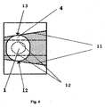
- the sectional drawing along AB of FIG. 3 shown in FIG. 4 shows appropriately designed head pieces (4) of the pile with strip-shaped elements (12) and approximately circular endings (13) which fit into the conical guide rails (11) of the clamping bracket (7). inserted and fixed.
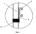
- FIG. 5 shows connecting pieces (6) designed as individual elements, which can be clamped onto the shaft (1) by means of clamping parts / sleeves (13). If the elastic webs (8) break or become fatigued, the connecting pieces (6) can be replaced without any problems.
- the arrangement variant of the clamp holder (7) shown in FIG. 6 with its guide rails (11) running parallel to the shaft enables the strut elements (8) to be introduced from above or below.
Landscapes
- Engineering & Computer Science (AREA)
- Architecture (AREA)
- Civil Engineering (AREA)
- Structural Engineering (AREA)
- Catching Or Destruction (AREA)
Abstract
Description
So kann bei starken Richtungsänderungen beim Aufstecken der Zäune ( Eckbereiche ) meist keine ausreichende Zug-Spannung der Drähte bzw. Bänder erzielt werden. Auch bei sehr lang ausgeführten Zaunanlagen sind die erforderlichen Zug-Spannungen oft nicht erreichbar.
- Figur 1
- eine schematische Ansicht eines erfindungsgemäßen Pfahles und in Vergrößerung die Klemmhalterung
- Figur 2
- eine schematische Ansicht eines Pfahles mit einem separaten Verstrebungselement ( Stütze )
- Figur 3
- eine schematische Ansicht eines Pfahles , bei dem das Verstrebungelement identisch mit dem Pfahl ist.
- Figur 4
- Draufsicht auf den Schnitt A-B in Fig. 3 ( konische Führungsschienen und Kopfstück )
- Figur 5
- schematische Ansicht eines aufklemmbaren Verbindungsstückes
- Figur 6
- Anordnung der Verbindungstücke zum Einführen der Verstrebungselemente von oben oder unten
In die Klemmhälterung (7) kann eine gesondertes Verstrebungselement (9) eingeschoben werden, wie in Figur 2 gezeigt ist. Hierbei ist das Kopfstück (10 ) des Verstrebungselements derart ausgebildet und dimensioniert, daß im Zusammenspiel mit der Klemmhalterung (7) eine feste , jedoch wieder lösbare Verbindung realisiert werden kann. Dies kann auf vielerlei an sich bekannten Arten geschehen . Anschließend kann das geklemmte Verstrebungselement (9) zusammen mit der Klemmhalterung seitlich abgebogen werden und seine Stützfunktion erfüllen. Dies wird durch den entsprechend ausgebildeten elastischen Steg (8) ermöglicht. Die elastischen Eigenschaften können durch geeignete Auswahl an Materialien ( Polyolefin-Polymere z.B. Polypropylen etc. ) und entspechender Dimensionierung der Dicke und/oder Breite des Steges (8) erhalten werden. Nach dem Ausbau des Verstrebungselments schnellt die Klemmhalterung in den Ausgangszustand zurück. Auf diese Art und Weise können in einem begrenzten Bereich beliebige Winkel zwischen Schaft (1) und Verstrebungselement (9) verwirklicht werden.
Die in Figur 4 gezeigte Schnittzeichnung entlang A-B von Fig. 3 zeigt entsprechend ausgebildeten Kopfstücke (4) des Pfahles mit streifenförmigen Elementen (12) und in etwa kreisförmigen Endungen (13), die in die konisch verlaufenden Führungsschienen (11) der Klemmhalterung (7) eingeschoben und fixiert werden.
Die in Figur 6 gezeigte Anordnungsvariante der Klemmhalterung (7) mit ihren parallel zum Schaft verlaufenden Führungsschienen (11) ermöglicht eine Einführung der Verstrebungselemente (8) von oben bzw. unten.
Claims (10)
- Pfahl aus Kunststoff für landwirtschaftliche Zaunanlagen mit einem Schaft (1), einen an diesem befestigten Steckfuß (2) mit ggf. einem Trittsteg (3), einem Kopftstück (4) und mindestens einem Befestigungselement (5) für Drähte oder Bänder,
dadurch gekennzeichnet, daß
am Schaft (1) mindestens ein Verbindungsstück (6) vorgesehen ist, das eine Klemmhalterung (7) zum Befestigen von Verstrebungselementen ( Stützen ) (9) aufweist und mittels Stege (8) mit den Schaft verbunden ist, wobei die Kopfstücke (10) der Verstrebungselemente (9) korrespondierend zu der Klemmhalterung (7) ausgebildet sind, um lösbar aufgeschoben und geklemmt zu werden. - Pfahl aus Kunststoff für landwirtschaftliche Zaunanlagen nach Anspruch 1, dadurch gekennzeichnet, daß der Pfahl und die Verstrebungselemente ( Stützen ) (9) identisch ausgebildet sind.
- Pfahl aus Kunststoff für landwirtschaftliche Zaunanlagen nach Anspruch 1 und 2, dadurch gekennzeichnet, daß das Verbindungsstück (6) mittels eines reversibel elastischen Steges (8) mit dem Schaft (1) verbunden ist.
- Pfahl aus Kunststoff für landwirtschaftliche Zaunanlagen nach einem der Ansprüche 1 bis 3, dadurch gekennzeichnet, daß das Verbindungsstück (6) Klemmhalterungen (7) in Form von parallel oder konisch verlaufenden Führungsschienen ( 11 ) aufweist.
- Pfahl aus Kunststoff für landwirtschaftliche Zaunanlagen nach einem der Ansprüche 1 bis 4, dadurch gekennzeichnet, daß die Kopfstücke (4), (9) des Pfahles oder der Verstrebungselemente (8) als beidseitig senkrecht vom Schaft abstehende streifenförmige Elemente (12) ausgebildet sind, deren beide Ränder im wesentlichen kreisförmige Endungen (13) aufweisen.
- Pfahl aus Kunststoff für landwirtschaftliche Zaunanlagen nach einem der Ansprüche 1 bis 5 , dadurch gekennzeichnet, daß die Verbindungsstücke (6) derart angeordnet sind, daß der Pfahl oder die Verstrebungselemente (8) von oben/unten oder von der Seite in die Führungsschienen (11) eingeführt werden können.
- Pfahl aus Kunststoff für landwirtschaftliche Zaunanlagen nach einem der Ansrpüche 1 bis 6, dadurch gekennzeichnet , daß die Verbindungsstücke (6) direkt gegenüberliegend am Schaft angeordnet werden.
- Pfahl aus Kunststoff für landwirtschaftliche Zaunanlagen nach einem der Ansprüche 1 bis 7 dadurch gekennzeichnet, daß die Verbindungsstücke (6) als Einzelelmente ausgebildet sind und mittels Klemmteile/-manschetten (14) auf den Schaft geklemmt werden.
- Pfahl aus Kunststoff für landwirtschaftliche Zaunanlagen nach einem der Ansprüche 1 bis 7, dadurch gekennzeichnet, daß die Verbindungsstücke (6) direkt auf den Schaft (1) aufgespritzt werden.
- Pfahl aus Kunststoff für landwirtschaftliche Zaunanlagen nach einem der Ansprüche 1 bis 7, dadurch gekennzeichnet, daß der Pfahl mit den Verbindungstücken (6) als einstückiges Teil gespritzt wird.
Priority Applications (1)
| Application Number | Priority Date | Filing Date | Title |
|---|---|---|---|
| EP98121698A EP1001113A1 (de) | 1998-11-13 | 1998-11-13 | Weidenzaunpfahl mit integriertem Abstützsystem |
Applications Claiming Priority (1)
| Application Number | Priority Date | Filing Date | Title |
|---|---|---|---|
| EP98121698A EP1001113A1 (de) | 1998-11-13 | 1998-11-13 | Weidenzaunpfahl mit integriertem Abstützsystem |
Publications (1)
| Publication Number | Publication Date |
|---|---|
| EP1001113A1 true EP1001113A1 (de) | 2000-05-17 |
Family
ID=8232974
Family Applications (1)
| Application Number | Title | Priority Date | Filing Date |
|---|---|---|---|
| EP98121698A Withdrawn EP1001113A1 (de) | 1998-11-13 | 1998-11-13 | Weidenzaunpfahl mit integriertem Abstützsystem |
Country Status (1)
| Country | Link |
|---|---|
| EP (1) | EP1001113A1 (de) |
Citations (6)
| Publication number | Priority date | Publication date | Assignee | Title |
|---|---|---|---|---|
| BE542343A (de) * | ||||
| FR2151991A7 (de) * | 1971-08-31 | 1973-04-20 | Kontinentale Eisenhandel | |
| FR2264946A1 (de) * | 1974-03-18 | 1975-10-17 | Bekaert Sa Nv | |
| AT359732B (de) * | 1978-05-18 | 1980-11-25 | Blum Reinhold | Ringfoermiger tragteil zur halterung von spann- draehten und gegenstreben an zaunpfosten |
| FR2514395A1 (fr) * | 1981-10-13 | 1983-04-15 | Dossetto Dominique | Piquet de cloture universel a jambes de force orientables et identiques |
| US5139235A (en) * | 1991-07-26 | 1992-08-18 | Kilmer Willis G | Corner fence post system |
-
1998
- 1998-11-13 EP EP98121698A patent/EP1001113A1/de not_active Withdrawn
Patent Citations (6)
| Publication number | Priority date | Publication date | Assignee | Title |
|---|---|---|---|---|
| BE542343A (de) * | ||||
| FR2151991A7 (de) * | 1971-08-31 | 1973-04-20 | Kontinentale Eisenhandel | |
| FR2264946A1 (de) * | 1974-03-18 | 1975-10-17 | Bekaert Sa Nv | |
| AT359732B (de) * | 1978-05-18 | 1980-11-25 | Blum Reinhold | Ringfoermiger tragteil zur halterung von spann- draehten und gegenstreben an zaunpfosten |
| FR2514395A1 (fr) * | 1981-10-13 | 1983-04-15 | Dossetto Dominique | Piquet de cloture universel a jambes de force orientables et identiques |
| US5139235A (en) * | 1991-07-26 | 1992-08-18 | Kilmer Willis G | Corner fence post system |
Similar Documents
| Publication | Publication Date | Title |
|---|---|---|
| DE60129182T2 (de) | Modularer Zaun | |
| DE69013641T2 (de) | Extrudiertes Profil zur Verwendung als First oder Rinne in einem Foliengewächshaus sowie Gewächshaus mit einem dergleichen Profil. | |
| DE3207492A1 (de) | Pfahl fuer einen elektrozaun und verfahren zu seiner herstellung | |
| DE60211278T2 (de) | Modularer Zaun | |
| DE202023100298U1 (de) | Anordnung und Befestigungsadapter zum Anbringen von Solarmodulen an einer Haltekonstruktion, die auf einer landwirtschaftlichen Fläche errichtet ist | |
| EP3374985B1 (de) | Befestigungsvorrichtung | |
| DE3839369A1 (de) | Verbindungselement und verfahren zum verbinden von voll- oder leimholzbalken in gleicher ebene | |
| EP1422362B1 (de) | Vorrichtung zum Befestigen von Zaungittermatten an Zaunsäulen | |
| EP4403845A1 (de) | Anordnung und befestigungsadapter zum anbringen von solarmodulen an einer haltekonstruktion, die auf einer landwirtschaftlichen fläche errichtet ist | |
| DE8915921U1 (de) | Pfosten, der wenigstens teilweise aus einem Metallprofil besteht | |
| DE8701832U1 (de) | Scharnierelement | |
| EP0749686A2 (de) | Weidezaunpfahl | |
| DE69610594T2 (de) | Zaunhalter | |
| DE3500969A1 (de) | Abdeckplatte zum abdecken des bodens im bereich von aus dem boden herausragenden halterungen, pfaehlen u.a. | |
| DE2706493A1 (de) | Pfahl fuer wildwechselanlagen | |
| DE20015220U1 (de) | Vogel-Abweisvorrichtung | |
| DE202019102577U1 (de) | Klemmelement, Aufsatzleitpfosten und Aufsatzleitpfostenanordnung | |
| DE102019107121A1 (de) | Zaunpfosten mit integriertem Montagefuß | |
| DE202023101351U1 (de) | Vorrichtung zum Raubtierschutz bei Einfriedungen | |
| DE60226083T2 (de) | Montageteil für Zäune | |
| DE29716305U1 (de) | Bodenhalterung | |
| DE3412355A1 (de) | Schutzzaun mit stachelelementen | |
| DE1684969C (de) | Holmenzaun | |
| DE1684999C (de) | Zaun mit maschenartigem Bespannungs material | |
| DE9400991U1 (de) | Vorrichtung zum Abstützen eines Baumes |
Legal Events
| Date | Code | Title | Description |
|---|---|---|---|
| PUAI | Public reference made under article 153(3) epc to a published international application that has entered the european phase |
Free format text: ORIGINAL CODE: 0009012 |
|
| AK | Designated contracting states |
Kind code of ref document: A1 Designated state(s): AT BE CH DE ES FI FR IT LI LU NL PT SE |
|
| AX | Request for extension of the european patent |
Free format text: AL;LT;LV;MK;RO;SI |
|
| 17P | Request for examination filed |
Effective date: 20000810 |
|
| AKX | Designation fees paid |
Free format text: AT BE CH DE ES FI FR IT LI LU NL PT SE |
|
| 17Q | First examination report despatched |
Effective date: 20030627 |
|
| GRAP | Despatch of communication of intention to grant a patent |
Free format text: ORIGINAL CODE: EPIDOSNIGR1 |
|
| STAA | Information on the status of an ep patent application or granted ep patent |
Free format text: STATUS: THE APPLICATION IS DEEMED TO BE WITHDRAWN |
|
| 18D | Application deemed to be withdrawn |
Effective date: 20041005 |