EP1001141A2 - Verfahren zum Betreiben einer fremdgezündeten Viertakt-Brennkraftmaschine - Google Patents
Verfahren zum Betreiben einer fremdgezündeten Viertakt-Brennkraftmaschine Download PDFInfo
- Publication number
- EP1001141A2 EP1001141A2 EP99890345A EP99890345A EP1001141A2 EP 1001141 A2 EP1001141 A2 EP 1001141A2 EP 99890345 A EP99890345 A EP 99890345A EP 99890345 A EP99890345 A EP 99890345A EP 1001141 A2 EP1001141 A2 EP 1001141A2
- Authority
- EP
- European Patent Office
- Prior art keywords
- intake
- exhaust
- internal combustion
- combustion engine
- der
- Prior art date
- Legal status (The legal status is an assumption and is not a legal conclusion. Google has not performed a legal analysis and makes no representation as to the accuracy of the status listed.)
- Withdrawn
Links
Images
Classifications
-
- F—MECHANICAL ENGINEERING; LIGHTING; HEATING; WEAPONS; BLASTING
- F02—COMBUSTION ENGINES; HOT-GAS OR COMBUSTION-PRODUCT ENGINE PLANTS
- F02D—CONTROLLING COMBUSTION ENGINES
- F02D13/00—Controlling the engine output power by varying inlet or exhaust valve operating characteristics, e.g. timing
- F02D13/02—Controlling the engine output power by varying inlet or exhaust valve operating characteristics, e.g. timing during engine operation
- F02D13/0203—Variable control of intake and exhaust valves
- F02D13/0215—Variable control of intake and exhaust valves changing the valve timing only
- F02D13/0219—Variable control of intake and exhaust valves changing the valve timing only by shifting the phase, i.e. the opening periods of the valves are constant
-
- F—MECHANICAL ENGINEERING; LIGHTING; HEATING; WEAPONS; BLASTING
- F01—MACHINES OR ENGINES IN GENERAL; ENGINE PLANTS IN GENERAL; STEAM ENGINES
- F01L—CYCLICALLY OPERATING VALVES FOR MACHINES OR ENGINES
- F01L1/00—Valve-gear or valve arrangements, e.g. lift-valve gear
- F01L1/34—Valve-gear or valve arrangements, e.g. lift-valve gear characterised by the provision of means for changing the timing of the valves without changing the duration of opening and without affecting the magnitude of the valve lift
-
- F—MECHANICAL ENGINEERING; LIGHTING; HEATING; WEAPONS; BLASTING
- F02—COMBUSTION ENGINES; HOT-GAS OR COMBUSTION-PRODUCT ENGINE PLANTS
- F02D—CONTROLLING COMBUSTION ENGINES
- F02D13/00—Controlling the engine output power by varying inlet or exhaust valve operating characteristics, e.g. timing
- F02D13/02—Controlling the engine output power by varying inlet or exhaust valve operating characteristics, e.g. timing during engine operation
- F02D13/0253—Fully variable control of valve lift and timing using camless actuation systems such as hydraulic, pneumatic or electromagnetic actuators, e.g. solenoid valves
-
- F—MECHANICAL ENGINEERING; LIGHTING; HEATING; WEAPONS; BLASTING
- F02—COMBUSTION ENGINES; HOT-GAS OR COMBUSTION-PRODUCT ENGINE PLANTS
- F02D—CONTROLLING COMBUSTION ENGINES
- F02D13/00—Controlling the engine output power by varying inlet or exhaust valve operating characteristics, e.g. timing
- F02D13/02—Controlling the engine output power by varying inlet or exhaust valve operating characteristics, e.g. timing during engine operation
- F02D13/0261—Controlling the valve overlap
-
- F—MECHANICAL ENGINEERING; LIGHTING; HEATING; WEAPONS; BLASTING
- F02—COMBUSTION ENGINES; HOT-GAS OR COMBUSTION-PRODUCT ENGINE PLANTS
- F02D—CONTROLLING COMBUSTION ENGINES
- F02D13/00—Controlling the engine output power by varying inlet or exhaust valve operating characteristics, e.g. timing
- F02D13/02—Controlling the engine output power by varying inlet or exhaust valve operating characteristics, e.g. timing during engine operation
- F02D13/0269—Controlling the valves to perform a Miller-Atkinson cycle
-
- F—MECHANICAL ENGINEERING; LIGHTING; HEATING; WEAPONS; BLASTING
- F02—COMBUSTION ENGINES; HOT-GAS OR COMBUSTION-PRODUCT ENGINE PLANTS
- F02M—SUPPLYING COMBUSTION ENGINES IN GENERAL WITH COMBUSTIBLE MIXTURES OR CONSTITUENTS THEREOF
- F02M26/00—Engine-pertinent apparatus for adding exhaust gases to combustion-air, main fuel or fuel-air mixture, e.g. by exhaust gas recirculation [EGR] systems
- F02M26/01—Internal exhaust gas recirculation, i.e. wherein the residual exhaust gases are trapped in the cylinder or pushed back from the intake or the exhaust manifold into the combustion chamber without the use of additional passages
-
- F—MECHANICAL ENGINEERING; LIGHTING; HEATING; WEAPONS; BLASTING
- F02—COMBUSTION ENGINES; HOT-GAS OR COMBUSTION-PRODUCT ENGINE PLANTS
- F02B—INTERNAL-COMBUSTION PISTON ENGINES; COMBUSTION ENGINES IN GENERAL
- F02B1/00—Engines characterised by fuel-air mixture compression
- F02B1/02—Engines characterised by fuel-air mixture compression with positive ignition
- F02B1/04—Engines characterised by fuel-air mixture compression with positive ignition with fuel-air mixture admission into cylinder
-
- F—MECHANICAL ENGINEERING; LIGHTING; HEATING; WEAPONS; BLASTING
- F02—COMBUSTION ENGINES; HOT-GAS OR COMBUSTION-PRODUCT ENGINE PLANTS
- F02B—INTERNAL-COMBUSTION PISTON ENGINES; COMBUSTION ENGINES IN GENERAL
- F02B75/00—Other engines
- F02B75/02—Engines characterised by their cycles, e.g. six-stroke
- F02B2075/022—Engines characterised by their cycles, e.g. six-stroke having less than six strokes per cycle
- F02B2075/027—Engines characterised by their cycles, e.g. six-stroke having less than six strokes per cycle four
-
- F—MECHANICAL ENGINEERING; LIGHTING; HEATING; WEAPONS; BLASTING
- F02—COMBUSTION ENGINES; HOT-GAS OR COMBUSTION-PRODUCT ENGINE PLANTS
- F02B—INTERNAL-COMBUSTION PISTON ENGINES; COMBUSTION ENGINES IN GENERAL
- F02B2275/00—Other engines, components or details, not provided for in other groups of this subclass
- F02B2275/32—Miller cycle
-
- Y—GENERAL TAGGING OF NEW TECHNOLOGICAL DEVELOPMENTS; GENERAL TAGGING OF CROSS-SECTIONAL TECHNOLOGIES SPANNING OVER SEVERAL SECTIONS OF THE IPC; TECHNICAL SUBJECTS COVERED BY FORMER USPC CROSS-REFERENCE ART COLLECTIONS [XRACs] AND DIGESTS
- Y02—TECHNOLOGIES OR APPLICATIONS FOR MITIGATION OR ADAPTATION AGAINST CLIMATE CHANGE
- Y02T—CLIMATE CHANGE MITIGATION TECHNOLOGIES RELATED TO TRANSPORTATION
- Y02T10/00—Road transport of goods or passengers
- Y02T10/10—Internal combustion engine [ICE] based vehicles
- Y02T10/12—Improving ICE efficiencies
Definitions
- the invention relates to a method for operating a spark-ignited four-stroke internal combustion engine with at least one intake valve and at least one exhaust valve per cylinder, wherein intake and exhaust valves are operated via a common camshaft.
- This throttling of the intake flow leads to a thermodynamic loss that the Fuel consumption of the internal combustion engine increases.
- the potential for reducing consumption the internal combustion engine bypassing this throttling can be about 25% are estimated. Part of this potential for improvement can be used if a reduction in throttling is possible in the partial load range.
- AT 2 434 U1 is a spark-ignited internal combustion engine with several cylinders and a device for charge dilution for air or recirculated exhaust gas, which one for all cylinders has a row of common manifold into which the Feed line opens and which with at least one distribution channel per cylinder an inlet duct is fluidly connected.
- the internal combustion engine shows a tangential channel per cylinder to generate a rotation of the cylinder charge around the Cylinder axis and a neutral channel, which is neither a pronounced swirl flow nor causes a tumble flow.
- Such internal combustion engines tolerate high exhaust gas recirculation quantities.
- AT 402 535 B is also an internal combustion engine with one neutral channel and one Tangential channel known per cylinder, with fuel in both inlet channels via one between the injection device arranged in the inlet channels is introduced.
- the two inlet channels open into the combustion chamber at predefined angles, so that on the one hand at Partial load a high swirl of the charge is achieved without the charge inflow at full load due to poorer flow values.
- EP 0 764 773 A1 discloses a similar internal combustion engine, each in a cylinder opening neutral and tangential channels, the fuel injection in the controlled by a throttle device neutral channel.
- the throttle device enables a defined minimum flow when closed. With this training stable radial mixture stratification can be achieved.
- the DE 1 222 735 B describes an internal combustion engine in which the opening time of the Intake valve is shifted far into the exhaust period.
- DE 1 401 228 B shows a diesel engine in which combustion gases enter the intake system flow by changing the timing of the exhaust and intake valves.
- DE 21 25 368 A shows a four-stroke engine, in which the exhaust valve during the intake stroke opened shortly before the maximum intake valve lift by means of an additional cam becomes.
- DE 26 38 651 A discloses an internal combustion engine in which the exhaust valve before Close the suction valve and when the piston is in position just before reaching the lower one Dead center is opened again by an additional cam.
- the object of the invention is to avoid the disadvantages mentioned and a method develop with which a throttle poor in a spark-ignited internal combustion engine Part load operation can be achieved in the simplest possible way.
- this is achieved in that at partial load through a phase adjustment the camshaft both the intake timing and the exhaust timing by a crankshaft angle from about 30 ° to 100 °, preferably about 40 ° to 80 °, shifted late becomes. Since intake and exhaust timing are shifted late in synchronism avoid that there is a loss of gas exchange near top dead center in the early intake phase causes negative pressure when the intake timing is late becomes. At the same time, the delayed closing of the exhaust valves allows an internal Achieve exhaust gas recirculation in the cylinder chamber.
- the intake closes at about 80 ° to 150 °, preferably at about 90 ° to 140 ° after the charge change following bottom dead center.
- control time is adjusted by twisting and / or shifting the common camshaft for intake and exhaust valves, for example pneumatic, hydraulic, electrical or mechanical.
- intake and exhaust valves for example pneumatic, hydraulic, electrical or mechanical.
- cam shifting the advantage of an extremely low manufacturing and control effort. This also has in comparison to the timing adjustment for DOHC engines
- inventive method has the advantage that an improvement in consumption with much less Effort can be realized.
- the method according to the invention thus enables significant fuel savings achieve.
- the late exhaust end at the beginning of the intake stroke enables internal exhaust gas recirculation, which mostly saves the effort for external exhaust gas recirculation can be.
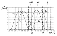
- valve lift H is plotted over the crank position KW in degrees crank angle for intake valves and exhaust valves, in each case for full-load operation and part-load operation.
- Reference symbol E T denotes the valve lift H of the intake valves at partial load
- E V the valve lift of the intake valves at full load.
- the valve stroke H of the exhaust valves for partial load and for full load is designated as A or T V A.
- the timing of the exhaust valve stroke is synchronized with the adjustment of the intake valve stroke late. By shifting the intake timing late, dethrottling is effected, so that during the push-out phase R, the excess air in the combustion chamber is blown back into the intake manifold against ambient pressure.
- the inventive method is an unthrottled operation with extremely little constructive and tax technical effort possible. Therefore, there are extremely few Loss of gas exchange and low fuel consumption. Because for tax time adjustment only a single conventional camshaft phasing device common to intake and exhaust valves can be used is compared to a fully variable Valve lift and, compared to the timing adjustment in DOHC engines, a much smaller one Effort required.
Landscapes
- Engineering & Computer Science (AREA)
- Mechanical Engineering (AREA)
- General Engineering & Computer Science (AREA)
- Chemical & Material Sciences (AREA)
- Combustion & Propulsion (AREA)
- Physics & Mathematics (AREA)
- Electromagnetism (AREA)
- Output Control And Ontrol Of Special Type Engine (AREA)
- Valve-Gear Or Valve Arrangements (AREA)
Abstract
Description
- A) Magerbetrieb:
- a) homogen: bei gegebener Kraftstoffmenge ist eine Entdrosselung durch Erhöhung der Luftmenge (Abmagerung des Gemisches) möglich. Nun wird aber durch Abmagerung die Verbrennung verlangsamt, was zu einem niedrigeren thermodynamischen Wirkungsgrad führt. Um die Entdrosselung zu erhöhen sind also Maßnahmen erforderlich, die die Abmagerungsfähigkeit verbessern. Für die Einhaltung der Emissionsgrenzwerte ist für diesen Betrieb eine spezielle Abgasnachbehandlung für Stickoxide (DENOX-Katalysator) nötig.
- b) geschichtet: der Verlangsamung der Verbrennung kann auch durch Schichtung des Gemisches im Brennraum entgegengewirkt werden. Dabei wird versucht, in der Umgebung der Zündkerze zum Zeitpunkt der Entflammung ein fetteres Gemisch als im restlichen Brennraum zu erzielen. Bei Einspritzung ins Saugrohr ist es wegen des homogenisierenden Effektes der Ladungsbewegung nicht möglich, eine nennenswerte Schichtung zum Zündzeitpunkt aufrechtzuerhalten. Bei direkter Einspritzung des Kraftstoffes in den Brennraum kann bei Einspritzung kurz vor der Entflammung eine stabile, reproduzierbare Schichtung und damit ein ungedrosselter Betrieb erzielt werden. Auch bei diesem Verfahren muß zur Einhaltung der Emissionsgrenzwerte im Fahrzeug ein DENOX-Kat verwendet werden. Zusätzlich muß bei der kurzen zur Verfügung stehenden Zeit zur Gemischbildung besonderes Augenmerk auf Rußbildung bzw. deren Vermeidung geachtet werden. Der technische Aufwand zur Realisierung einer direkten Einspritzung ist deutlich höher als bei einer Saugrohreinspritzung.
Claims (5)
- Verfahren zum Betreiben einer fremdgezündeten Viertakt-Brennkraftmaschine mit zumindest einem Einlaßventil und zumindest einem Auslaßventil pro Zylinder, wobei Einund Auslaßventile über eine gemeinsame Nockenwelle betätigt werden, dadurch gekennzeichnet , daß bei Teillast durch eine Phasenverstellung der Nockenwelle sowohl die Einlaßsteuerzeit als auch die Auslaßsteuerzeit um einen Kurbelwellen-Winkel von etwa 30° bis 100°, vorzugsweise etwa 40° bis 80°, nach Spät verschoben wird.
- Verfahren nach Anspruch 1, dadurch gekennzeichnet, daß bei Spätverstellung der Einlaßsteuerzeit der Einlaßschluß bei etwa 80° bis 150°, vorzugsweise bei etwa 90° bis 140° nach dem auf dem Ladungswechsel folgenden unteren Totpunkt erfolgt.
- Verfahren nach Anspruch 1 oder 2, dadurch gekennzeichnet, daß die Brennkraftmaschine ungedrosselt betrieben wird.
- Verfahren nach einem der Ansprüche 1 bis 3, dadurch gekennzeichnet, daß die Phasenverstellung der Nockenwelle durch Verdrehen und/oder Verschieben der Nockenwelle erfolgt.
- Verfahren nach einem der Ansprüche 1 bis 4, dadurch gekennzeichnet, daß während der Einlaßphase eine asymmetrische Einlaßströmung generiert wird.
Applications Claiming Priority (2)
| Application Number | Priority Date | Filing Date | Title |
|---|---|---|---|
| AT73498U | 1998-11-09 | ||
| AT0073498U AT3134U1 (de) | 1998-11-09 | 1998-11-09 | Verfahren zum betreiben einer fremdgezündeten viertakt-brennkraftmaschine |
Publications (2)
| Publication Number | Publication Date |
|---|---|
| EP1001141A2 true EP1001141A2 (de) | 2000-05-17 |
| EP1001141A3 EP1001141A3 (de) | 2001-08-29 |
Family
ID=3498405
Family Applications (1)
| Application Number | Title | Priority Date | Filing Date |
|---|---|---|---|
| EP99890345A Withdrawn EP1001141A3 (de) | 1998-11-09 | 1999-10-28 | Verfahren zum Betreiben einer fremdgezündeten Viertakt-Brennkraftmaschine |
Country Status (2)
| Country | Link |
|---|---|
| EP (1) | EP1001141A3 (de) |
| AT (1) | AT3134U1 (de) |
Cited By (1)
| Publication number | Priority date | Publication date | Assignee | Title |
|---|---|---|---|---|
| EP1338776A1 (de) * | 2002-02-20 | 2003-08-27 | Ford Global Technologies, Inc., A subsidiary of Ford Motor Company | Viertakt-Ottomotor mit separat verstellbaren Nockenwellen sowie Steuerungsverfahren |
Families Citing this family (2)
| Publication number | Priority date | Publication date | Assignee | Title |
|---|---|---|---|---|
| AT5781U1 (de) | 2001-04-19 | 2002-11-25 | Avl List Gmbh | Brennkraftmaschine mit mindestens einem einlassventil |
| AT500665B1 (de) * | 2005-11-15 | 2007-05-15 | Avl List Gmbh | Brennkraftmaschine mit einem zylinderkopf |
Family Cites Families (6)
| Publication number | Priority date | Publication date | Assignee | Title |
|---|---|---|---|---|
| US1819743A (en) * | 1931-08-18 | Mechanism for automatically and synchronously adjusting the ignition | ||
| US2410411A (en) * | 1942-05-19 | 1946-11-05 | Fairchild Engine & Airplane | Engine valve control mechanism |
| US3888217A (en) * | 1973-09-24 | 1975-06-10 | Charles A Hisserich | Camshaft belt drive for variable valve timing |
| US5224460A (en) * | 1992-02-07 | 1993-07-06 | Ford Motor Company | Method of operating an automotive type internal combustion engine |
| US5327859A (en) * | 1993-06-09 | 1994-07-12 | General Motors Corporation | Engine timing drive with fixed and variable phasing |
| US5957096A (en) * | 1998-06-09 | 1999-09-28 | Ford Global Technologies, Inc. | Internal combustion engine with variable camshaft timing, charge motion control valve, and variable air/fuel ratio |
-
1998
- 1998-11-09 AT AT0073498U patent/AT3134U1/de unknown
-
1999
- 1999-10-28 EP EP99890345A patent/EP1001141A3/de not_active Withdrawn
Cited By (1)
| Publication number | Priority date | Publication date | Assignee | Title |
|---|---|---|---|---|
| EP1338776A1 (de) * | 2002-02-20 | 2003-08-27 | Ford Global Technologies, Inc., A subsidiary of Ford Motor Company | Viertakt-Ottomotor mit separat verstellbaren Nockenwellen sowie Steuerungsverfahren |
Also Published As
| Publication number | Publication date |
|---|---|
| AT3134U1 (de) | 1999-10-25 |
| EP1001141A3 (de) | 2001-08-29 |
Similar Documents
| Publication | Publication Date | Title |
|---|---|---|
| EP1296043B1 (de) | Brennkraftmaschine | |
| DE4232044C2 (de) | Brennkraftmaschine mit Funkenzündung | |
| DE69301470T2 (de) | Brennkraftmaschine | |
| DE69304228T2 (de) | Brennkraftmaschine mit variabler Hubventilsteuerung | |
| EP0663042B1 (de) | Hybridgesteuerter viertakt-ottomotor | |
| DE60303245T2 (de) | Regler für fremd gezündete Brennkraftmaschine | |
| DE60312941T2 (de) | Zündungsregler für eine fremdgezündete Brennkraftmaschine | |
| DE60002255T2 (de) | Brennkraftmaschine mit Abgasrückführung | |
| DE102004034505B4 (de) | Verfahren zum Betrieb einer Brennkraftmaschine | |
| EP1363010B1 (de) | Verfahren zum Betreiben einer fremdgezündeten Viertakt-Brennkraftmaschine mit Mehrfacheinspritzung | |
| DE602004001648T2 (de) | Steuervorrichtung für fremdgezündete Brennkraftmaschine | |
| WO1998042970A1 (de) | Verfahren zum vermindern von schädlichen abgasemissionen eines mit magerem kraftstoff/luftgemisch betriebenen otto-motores | |
| WO2009024170A1 (de) | Verbrennungskraftmaschine mit nockengesteuertem variablen ventiltrieb | |
| EP1338777B1 (de) | Viertakt-Ottomotor mit Nockenwellen-Verstellung | |
| EP0999357B1 (de) | Verfahren zum Betreiben einer fremdgezündeten Viertakt-Brennkraftmaschine mit indirekter Kraftstoffeinspritzung | |
| EP1191211B1 (de) | Verfahren zum Betreiben einer fremdgezündeten Brennkraftmaschine | |
| EP1338776B1 (de) | Viertakt-Ottomotor mit separat verstellbaren Nockenwellen sowie Steuerungsverfahren | |
| DE69400893T2 (de) | Viertaktbrennkraftmaschine | |
| EP1333158A1 (de) | Viertakt-Ottomotor mit Direkteinspritzung und Verfahren zur Ventilsteuerung | |
| AT3134U1 (de) | Verfahren zum betreiben einer fremdgezündeten viertakt-brennkraftmaschine | |
| DE102015200047B4 (de) | Verfahren zum Betreiben einer Brennkraftmaschine mit Teilabschaltung | |
| DE4244774C2 (de) | Brennkraftmaschine mit Abgasrückführung | |
| WO2005038210A1 (de) | Verfahren zum betrieb einer brennkraftmaschine | |
| DE60120604T2 (de) | Verfahren zur Steuerung einer Brennkraftmaschine zur Durchführung einer homogenen Verbrennung | |
| DE4411434C2 (de) | Betriebsverfahren für eine Brennkraftmaschine mit mindestens zwei Einlaßventilen |
Legal Events
| Date | Code | Title | Description |
|---|---|---|---|
| PUAI | Public reference made under article 153(3) epc to a published international application that has entered the european phase |
Free format text: ORIGINAL CODE: 0009012 |
|
| AK | Designated contracting states |
Kind code of ref document: A2 Designated state(s): AT BE CH CY DE DK ES FI FR GB GR IE IT LI LU MC NL PT SE |
|
| AX | Request for extension of the european patent |
Free format text: AL;LT;LV;MK;RO;SI |
|
| PUAL | Search report despatched |
Free format text: ORIGINAL CODE: 0009013 |
|
| AK | Designated contracting states |
Kind code of ref document: A3 Designated state(s): AT BE CH CY DE DK ES FI FR GB GR IE IT LI LU MC NL PT SE |
|
| AX | Request for extension of the european patent |
Free format text: AL;LT;LV;MK;RO;SI |
|
| 17P | Request for examination filed |
Effective date: 20010825 |
|
| AKX | Designation fees paid |
Free format text: DE FR GB IT |
|
| 17Q | First examination report despatched |
Effective date: 20020705 |
|
| STAA | Information on the status of an ep patent application or granted ep patent |
Free format text: STATUS: THE APPLICATION IS DEEMED TO BE WITHDRAWN |
|
| 18D | Application deemed to be withdrawn |
Effective date: 20021116 |