EP1001167B1 - Elektromagnetische Pumpe - Google Patents
Elektromagnetische Pumpe Download PDFInfo
- Publication number
- EP1001167B1 EP1001167B1 EP99122025A EP99122025A EP1001167B1 EP 1001167 B1 EP1001167 B1 EP 1001167B1 EP 99122025 A EP99122025 A EP 99122025A EP 99122025 A EP99122025 A EP 99122025A EP 1001167 B1 EP1001167 B1 EP 1001167B1
- Authority
- EP
- European Patent Office
- Prior art keywords
- plunger
- yoke
- electromagnetic pump
- cylinder
- plastic mold
- Prior art date
- Legal status (The legal status is an assumption and is not a legal conclusion. Google has not performed a legal analysis and makes no representation as to the accuracy of the status listed.)
- Expired - Lifetime
Links
Images


Classifications
-
- F—MECHANICAL ENGINEERING; LIGHTING; HEATING; WEAPONS; BLASTING
- F04—POSITIVE - DISPLACEMENT MACHINES FOR LIQUIDS; PUMPS FOR LIQUIDS OR ELASTIC FLUIDS
- F04B—POSITIVE-DISPLACEMENT MACHINES FOR LIQUIDS; PUMPS
- F04B17/00—Pumps characterised by combination with, or adaptation to, specific driving engines or motors
- F04B17/03—Pumps characterised by combination with, or adaptation to, specific driving engines or motors driven by electric motors
- F04B17/04—Pumps characterised by combination with, or adaptation to, specific driving engines or motors driven by electric motors using solenoids
- F04B17/046—Pumps characterised by combination with, or adaptation to, specific driving engines or motors driven by electric motors using solenoids the fluid flowing through the moving part of the motor
-
- F—MECHANICAL ENGINEERING; LIGHTING; HEATING; WEAPONS; BLASTING
- F01—MACHINES OR ENGINES IN GENERAL; ENGINE PLANTS IN GENERAL; STEAM ENGINES
- F01M—LUBRICATING OF MACHINES OR ENGINES IN GENERAL; LUBRICATING INTERNAL COMBUSTION ENGINES; CRANKCASE VENTILATING
- F01M1/00—Pressure lubrication
- F01M1/02—Pressure lubrication using lubricating pumps
- F01M2001/0207—Pressure lubrication using lubricating pumps characterised by the type of pump
- F01M2001/0223—Electromagnetic pumps
Definitions
- the plunger 2 reciprocates in the manner as mentioned previously.
- the discharge valve 12 is closed and the inlet valve 11 is opened, whereby oil is drawn into a pump chamber (a space between the discharge valve 12 and the inlet valve 11) from the nipple 6 and the center hole of the plunger 2, by way of a gap between the inlet valve 11 and the valve seat 24.
- the discharge valve 12 is opened and the inlet valve 11 is closed, whereby oil is forced out to an oil flow channel of the inner yoke 4 from the pump chamber, by way of the space between the discharge valve 12 and the valve seat 7.
- An engine control unit controls a pulse current which is to be applied to the coil 16 in response to a signal output from a sensor for detecting the working state of the engine, thus controlling the amount of engine oil to be supplied.
- the present invention provides an electromagnetic pump, in which a plunger is reciprocated within a cylinder by means of the restoration force of a spring and electromagnetic force acting on a magnetic circuit, comprising an inner yoke and the plunger, so as to reduce a magnetic gap between the inner yoke and the plunger, wherein the stroke of the plunger is limited by two planes of two members disposed so as to opposite each other with the cylinder interposed therebetween.
- a protuberance is formed on a plastic mold covering a coil for applying a magnetomotive force to the plunger, and the protuberance is deformed to fix the plastic mold by means of fixing an end yoke to an outer yoke by caulking while the plastic mold is housed within the space defined by the end yoke and an outer yoke, which constitute the magnetic circuit.
- FIG. 1 is a cross-sectional view showing an electromagnetic pump to be used as a separate oil pump of an engine according to a first embodiment of the present invention.
- An illustrated plunger 2 is slidably fitted into a cylinder 1 formed from non-magnetic material, such as aluminum or brass, and is forced rightward by means of a compression coil spring 8.
- An inner yoke 3 opposite the plunger 2 is pressingly fitted into an end yoke 4, and the end yoke 4 is fixed to an outer yoke 5 by means of caulking.
- a nipple 6 pressingly-fitted into the outer yoke 5 is in close proximity to the plunger 2.
- the plunger 2, the inner yoke 3, the end yoke 4, the outer yoke 5, and the nipple 6 are formed from magnetic material and constitute a magnetic circuit.
- the stroke of the plunger 2 is expressed by X-Y.
- the accuracy of the stroke of the plunger 2 is affected by only the dimensional accuracy of the cylinder 1 and the dimensional accuracy of the plunger 2.
- the dimensional accuracy of length of the cylinder 1 and the dimensional accuracy of length of the plunger 2 can be readily improved by means of turning. Accordingly, the accuracy of the stroke of the plunger 2 can be readily improved.
- the method of actuating the electromagnetic pump of the present embodiment is the same as that which has already been described in connection with the conventional example.
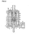
- FIG. 2 is a cross-sectional view showing an electromagnetic pump used as a separating oil pump of an engine according to a second embodiment of the present invention.
- a protuberance 23 is provided on the face of the plastic mold 14 facing the outer yoke 5.
- the height of the protuberance 23 is set such that a portion of the protuberance 23 is deformed when the edge of the outer yoke 5 is locked to the end yoke 4 by caulking while the plastic mold 14 is housed in the space between the end yoke 4 and the outer yoke 5.
- the protuberance is formed on the end face of the plastic mold.
- the edge of the outer yoke 5 is locked to the end yoke 4 by caulking while the plastic mold 14 is housed in the space between the end yoke 4 and the outer yoke 5, the protuberance is deformed, thus locking the plastic mold 14. Accordingly, the necessity for the O-ring can be reduced, and the number of components of the assembly can be diminished.
Landscapes
- Engineering & Computer Science (AREA)
- Physics & Mathematics (AREA)
- Fluid Mechanics (AREA)
- Mechanical Engineering (AREA)
- General Engineering & Computer Science (AREA)
- Electromagnetic Pumps, Or The Like (AREA)
- Details Of Reciprocating Pumps (AREA)
- Magnetically Actuated Valves (AREA)
Claims (4)
- Elektromagnetische Pumpe, in der sich ein Kolben (2) innerhalb eines Zylinders (1) mittels der Rückstellkraft einer Feder (8) und der elektromagnetischen Kraft, die auf einen Magnetkreis umfassend ein inneres Joch (3) und den Kolben (2) so wirkt, dass ein magnetischer Spalt zwischen dem inneren Joch (3) und dem Kolben (2) reduziert wird, hin- und herbewegt,
dadurch gekennzeichnet,
dass der Hub des Kolbens (2) begrenzt ist durch entsprechende Ebenen zweier Elemente (3, 20), welche so angeordnet sind, dass sie einander gegenüberliegen, wobei der Zylinder (1) dazwischen angeordnet ist, und
dass der Kolben (2) eine Stufe aufweist, die den Hub des Kolbens (2) begrenzt. - Elektromagnetische Pumpe, so wie sie in Anspruch 1 definiert ist, wobei eines der beiden Elemente (3, 20) einem ringförmigen Abstandsring (20) entspricht und der Abstandsring (20) mit dem Zylinder (1) mittels einer Wellenunterlegscheibe (21) in Anpresskontakt gebracht wird.
- Elektromagnetische Pumpe, so wie sie in Anspruch 1 oder 2 definiert ist, wobei ein Fluideinlasskanal innerhalb des Kolbens (2) eingeformt ist,
ein Federaufnahmeabschnitt, welcher sich auf die Innenseite des Einlasskanals des Kolbens (2) erstreckt, ist in dem Einlassventil (11), welches den Einlasskanal öffnet oder schließt, eingeformt, und
eine Feder (9) zum Einspannen des Einlassventils (11) ist an dem Federaufnahmeabschnitt verriegelt. - Elektromagnetische Pumpe, so wie sie in einem der Ansprüche 1-3 definiert ist, wobei eine Ausstülpung (23) an einem Plastikformkörper (14) ausgeformt ist, welcher eine Spule (16) zum Aufbringen einer magnetomotorischen Kraft auf den Kolben (2) abdeckt, und die Ausstülpung (23) deformiert ist, um den Plastikformkörper (14) mittels des Befestigens eines Endjoches (4) an dem äußeren Joch (5) durch Verstemmen zu befestigen, während der Plastikformkörper (14) innerhalb des Raumes aufgenommen ist, der durch das Endjoch (4) und ein äußeres Joch (5) definiert ist, die den Magnetkreis ausbilden.
Applications Claiming Priority (2)
| Application Number | Priority Date | Filing Date | Title |
|---|---|---|---|
| JP32325398A JP4203160B2 (ja) | 1998-11-13 | 1998-11-13 | 電磁ポンプ |
| JP32325398 | 1998-11-13 |
Publications (3)
| Publication Number | Publication Date |
|---|---|
| EP1001167A2 EP1001167A2 (de) | 2000-05-17 |
| EP1001167A3 EP1001167A3 (de) | 2000-11-15 |
| EP1001167B1 true EP1001167B1 (de) | 2007-01-10 |
Family
ID=18152732
Family Applications (1)
| Application Number | Title | Priority Date | Filing Date |
|---|---|---|---|
| EP99122025A Expired - Lifetime EP1001167B1 (de) | 1998-11-13 | 1999-11-12 | Elektromagnetische Pumpe |
Country Status (4)
| Country | Link |
|---|---|
| US (1) | US6273689B1 (de) |
| EP (1) | EP1001167B1 (de) |
| JP (1) | JP4203160B2 (de) |
| DE (1) | DE69934759T2 (de) |
Families Citing this family (17)
| Publication number | Priority date | Publication date | Assignee | Title |
|---|---|---|---|---|
| KR100444817B1 (ko) * | 2000-03-29 | 2004-08-18 | 주식회사 만도 | 브레이크 트랙션 콘트롤 시스템용 솔레노이드밸브 |
| DE60126056T2 (de) * | 2001-01-24 | 2007-07-12 | Mikuni Corp. | Kraftstoffzufuhrsystem |
| ITMI20010419A1 (it) * | 2001-03-01 | 2002-09-01 | Inc Dell Orto S P A | Pompa comandata da elettromagnete |
| ITMI20020271U1 (it) * | 2002-05-23 | 2003-11-24 | C E M E Engineering S P A | Elettropompa migliorata |
| JP4279527B2 (ja) * | 2002-09-13 | 2009-06-17 | 株式会社ミクニ | 電磁ポンプ |
| US7150606B2 (en) * | 2003-10-28 | 2006-12-19 | Motor Components Llc | Electromagnetic fuel pump |
| KR20050094005A (ko) * | 2004-03-17 | 2005-09-26 | 삼성광주전자 주식회사 | 리니어 압축기 |
| ATE499527T1 (de) * | 2007-03-15 | 2011-03-15 | Ceme Spa | Hydraulisch-elektromagnetische motorpumpe mit schwimmkolben |
| KR200446440Y1 (ko) * | 2008-05-09 | 2009-10-29 | 성신하스코 주식회사 | 기밀유지가 되는 솔레노이드 펌프 |
| JP5401175B2 (ja) * | 2009-06-03 | 2014-01-29 | 浜名湖電装株式会社 | 電磁ソレノイド装置 |
| US8783229B2 (en) | 2010-06-07 | 2014-07-22 | Caterpillar Inc. | Internal combustion engine, combustion charge formation system, and method |
| JP6229249B2 (ja) * | 2012-08-06 | 2017-11-15 | 株式会社リコー | 弁の故障検知装置 |
| ES1123905Y (es) * | 2014-08-19 | 2015-01-23 | Teylor Intelligent Processes Sl Empresa | Sistema magnético para bomba de camara estanca |
| CN104314804A (zh) * | 2014-09-26 | 2015-01-28 | 天纳克(苏州)排放系统有限公司 | 柱塞泵及其应用 |
| SE1550049A1 (sv) * | 2015-01-21 | 2016-07-22 | Osakeyhtiö Skf Ab | System, method & computer program product |
| JP6253623B2 (ja) * | 2015-09-14 | 2017-12-27 | 本田技研工業株式会社 | 燃料遮断弁 |
| DK179750B1 (en) | 2017-12-13 | 2019-05-07 | Hans Jensen Lubricators A/S | Large slow-running two-stroke engine and method of lubri-cating such engine, as well as an injector with an electric pumping system for such engine and method |
Family Cites Families (11)
| Publication number | Priority date | Publication date | Assignee | Title |
|---|---|---|---|---|
| US2393237A (en) * | 1942-05-07 | 1946-01-22 | Richard T Cornelius | Motor pump unit |
| GB1102555A (en) * | 1964-03-14 | 1968-02-07 | Eberspaecher Walter | Electromagnetically-actuated reciprocating piston pumps for liquids |
| GB1484674A (en) * | 1974-12-03 | 1977-09-01 | British Leyland Uk Ltd | Pump for liquids |
| US4306842A (en) * | 1978-06-28 | 1981-12-22 | Jidosha Kiki Co., Ltd. | Electromagnetic pumps |
| US4643653A (en) * | 1984-10-15 | 1987-02-17 | Jidosha Kiki Co., Ltd. | Electromagnetic pump |
| JPS61126385A (ja) * | 1984-11-22 | 1986-06-13 | Sawafuji Electric Co Ltd | 振動型圧縮機 |
| DE3719460A1 (de) * | 1986-07-03 | 1988-01-07 | Erich Becker | Verfahren zum antreiben eines mit einem schwingankerantrieb verbundenen foerderelementes einer pumpe sowie danach arbeitende pumpe |
| JPH0199981U (de) * | 1987-12-25 | 1989-07-05 | ||
| US5073095A (en) * | 1990-04-10 | 1991-12-17 | Purolator Product Company | Whisper quiet electromagnetic fluid pump |
| JPH0610831A (ja) * | 1992-06-26 | 1994-01-21 | Nippon Steel Corp | ソレノイドポンプ |
| IT1299987B1 (it) * | 1998-04-27 | 2000-04-04 | Magneti Marelli Spa | Pompa volumetrica. |
-
1998
- 1998-11-13 JP JP32325398A patent/JP4203160B2/ja not_active Expired - Fee Related
-
1999
- 1999-11-10 US US09/437,969 patent/US6273689B1/en not_active Expired - Fee Related
- 1999-11-12 DE DE69934759T patent/DE69934759T2/de not_active Expired - Lifetime
- 1999-11-12 EP EP99122025A patent/EP1001167B1/de not_active Expired - Lifetime
Also Published As
| Publication number | Publication date |
|---|---|
| DE69934759T2 (de) | 2007-10-11 |
| EP1001167A3 (de) | 2000-11-15 |
| JP4203160B2 (ja) | 2008-12-24 |
| JP2000145623A (ja) | 2000-05-26 |
| EP1001167A2 (de) | 2000-05-17 |
| DE69934759D1 (de) | 2007-02-22 |
| US6273689B1 (en) | 2001-08-14 |
Similar Documents
| Publication | Publication Date | Title |
|---|---|---|
| EP1001167B1 (de) | Elektromagnetische Pumpe | |
| JP4022857B2 (ja) | 電磁弁装置 | |
| US4524948A (en) | Electrically controlled pressure transducer valve | |
| JP4058749B2 (ja) | 電磁駆動装置およびそれを用いた電磁弁 | |
| US6899313B2 (en) | Magnetic actuator and method | |
| US5927614A (en) | Modular control valve for a fuel injector having magnetic isolation features | |
| JP4366835B2 (ja) | 電磁弁 | |
| US6737766B1 (en) | Magnetic actuator and method | |
| JP3219611B2 (ja) | 三方電磁弁及びその組立方法 | |
| US20020195151A1 (en) | Pulse-width modulated solenoid valve including axial stop spool valve | |
| US4540122A (en) | Electromagnetic unit fuel injector with pivotable armature | |
| JP6571898B2 (ja) | 電磁式駆動ユニット | |
| US4953825A (en) | Electro-magnetic proportional flow control valve | |
| US6938875B2 (en) | Proportional solenoid valve | |
| JP2000277327A (ja) | リニアソレノイド及びそれを用いた電磁弁 | |
| JP2002310322A (ja) | 電磁弁装置 | |
| JP3945357B2 (ja) | 燃料噴射装置 | |
| CA2219030C (en) | Electrically operated pressure control valve | |
| WO2004064083A2 (en) | Electromagnetic actuator for a fuel injector having an integral magnetic core and injector valve body | |
| US6715509B2 (en) | Electromagnetic valve and assembling method | |
| JPH07151257A (ja) | 電磁制御弁 | |
| JP2005030502A (ja) | 電磁式駆動ユニット及びそれを用いた電磁弁装置 | |
| JP2002250456A (ja) | 電磁制御弁のソレノイド構造 | |
| KR102364053B1 (ko) | 솔레노이드 | |
| JP4013440B2 (ja) | 電磁駆動装置及びそれを用いた電磁弁 |
Legal Events
| Date | Code | Title | Description |
|---|---|---|---|
| PUAI | Public reference made under article 153(3) epc to a published international application that has entered the european phase |
Free format text: ORIGINAL CODE: 0009012 |
|
| AK | Designated contracting states |
Kind code of ref document: A2 Designated state(s): DE FR IT |
|
| AX | Request for extension of the european patent |
Free format text: AL;LT;LV;MK;RO;SI |
|
| PUAL | Search report despatched |
Free format text: ORIGINAL CODE: 0009013 |
|
| AK | Designated contracting states |
Kind code of ref document: A3 Designated state(s): AT BE CH CY DE DK ES FI FR GB GR IE IT LI LU MC NL PT SE |
|
| AX | Request for extension of the european patent |
Free format text: AL;LT;LV;MK;RO;SI |
|
| 17P | Request for examination filed |
Effective date: 20010110 |
|
| AKX | Designation fees paid |
Free format text: DE FR IT |
|
| GRAP | Despatch of communication of intention to grant a patent |
Free format text: ORIGINAL CODE: EPIDOSNIGR1 |
|
| GRAS | Grant fee paid |
Free format text: ORIGINAL CODE: EPIDOSNIGR3 |
|
| GRAA | (expected) grant |
Free format text: ORIGINAL CODE: 0009210 |
|
| AK | Designated contracting states |
Kind code of ref document: B1 Designated state(s): DE FR IT |
|
| RAP1 | Party data changed (applicant data changed or rights of an application transferred) |
Owner name: MIKUNI CORPORATION |
|
| REF | Corresponds to: |
Ref document number: 69934759 Country of ref document: DE Date of ref document: 20070222 Kind code of ref document: P |
|
| ET | Fr: translation filed | ||
| PLBE | No opposition filed within time limit |
Free format text: ORIGINAL CODE: 0009261 |
|
| STAA | Information on the status of an ep patent application or granted ep patent |
Free format text: STATUS: NO OPPOSITION FILED WITHIN TIME LIMIT |
|
| 26N | No opposition filed |
Effective date: 20071011 |
|
| PGFP | Annual fee paid to national office [announced via postgrant information from national office to epo] |
Ref country code: DE Payment date: 20100122 Year of fee payment: 11 |
|
| REG | Reference to a national code |
Ref country code: DE Ref legal event code: R119 Ref document number: 69934759 Country of ref document: DE Effective date: 20110601 Ref country code: DE Ref legal event code: R119 Ref document number: 69934759 Country of ref document: DE Effective date: 20110531 |
|
| PG25 | Lapsed in a contracting state [announced via postgrant information from national office to epo] |
Ref country code: DE Free format text: LAPSE BECAUSE OF NON-PAYMENT OF DUE FEES Effective date: 20110531 |
|
| PGFP | Annual fee paid to national office [announced via postgrant information from national office to epo] |
Ref country code: FR Payment date: 20141127 Year of fee payment: 16 |
|
| PGFP | Annual fee paid to national office [announced via postgrant information from national office to epo] |
Ref country code: IT Payment date: 20141127 Year of fee payment: 16 |
|
| PG25 | Lapsed in a contracting state [announced via postgrant information from national office to epo] |
Ref country code: IT Free format text: LAPSE BECAUSE OF NON-PAYMENT OF DUE FEES Effective date: 20151112 |
|
| REG | Reference to a national code |
Ref country code: FR Ref legal event code: ST Effective date: 20160729 |
|
| PG25 | Lapsed in a contracting state [announced via postgrant information from national office to epo] |
Ref country code: FR Free format text: LAPSE BECAUSE OF NON-PAYMENT OF DUE FEES Effective date: 20151130 |