EP1001176B1 - Kupplungsanordnung - Google Patents
Kupplungsanordnung Download PDFInfo
- Publication number
- EP1001176B1 EP1001176B1 EP99308996A EP99308996A EP1001176B1 EP 1001176 B1 EP1001176 B1 EP 1001176B1 EP 99308996 A EP99308996 A EP 99308996A EP 99308996 A EP99308996 A EP 99308996A EP 1001176 B1 EP1001176 B1 EP 1001176B1
- Authority
- EP
- European Patent Office
- Prior art keywords
- connector
- apertures
- connector pieces
- pieces
- add
- Prior art date
- Legal status (The legal status is an assumption and is not a legal conclusion. Google has not performed a legal analysis and makes no representation as to the accuracy of the status listed.)
- Expired - Lifetime
Links
Images


Classifications
-
- F—MECHANICAL ENGINEERING; LIGHTING; HEATING; WEAPONS; BLASTING
- F16—ENGINEERING ELEMENTS AND UNITS; GENERAL MEASURES FOR PRODUCING AND MAINTAINING EFFECTIVE FUNCTIONING OF MACHINES OR INSTALLATIONS; THERMAL INSULATION IN GENERAL
- F16B—DEVICES FOR FASTENING OR SECURING CONSTRUCTIONAL ELEMENTS OR MACHINE PARTS TOGETHER, e.g. NAILS, BOLTS, CIRCLIPS, CLAMPS, CLIPS OR WEDGES; JOINTS OR JOINTING
- F16B7/00—Connections of rods or tubes, e.g. of non-circular section, mutually, including resilient connections
- F16B7/04—Clamping or clipping connections
- F16B7/044—Clamping or clipping connections for rods or tubes being in angled relationship
- F16B7/048—Clamping or clipping connections for rods or tubes being in angled relationship for rods or for tubes without using the innerside thereof
- F16B7/0486—Clamping or clipping connections for rods or tubes being in angled relationship for rods or for tubes without using the innerside thereof forming an abutting connection of at least one tube
-
- F—MECHANICAL ENGINEERING; LIGHTING; HEATING; WEAPONS; BLASTING
- F16—ENGINEERING ELEMENTS AND UNITS; GENERAL MEASURES FOR PRODUCING AND MAINTAINING EFFECTIVE FUNCTIONING OF MACHINES OR INSTALLATIONS; THERMAL INSULATION IN GENERAL
- F16B—DEVICES FOR FASTENING OR SECURING CONSTRUCTIONAL ELEMENTS OR MACHINE PARTS TOGETHER, e.g. NAILS, BOLTS, CIRCLIPS, CLAMPS, CLIPS OR WEDGES; JOINTS OR JOINTING
- F16B2200/00—Constructional details of connections not covered for in other groups of this subclass
- F16B2200/67—Rigid angle couplings
-
- Y—GENERAL TAGGING OF NEW TECHNOLOGICAL DEVELOPMENTS; GENERAL TAGGING OF CROSS-SECTIONAL TECHNOLOGIES SPANNING OVER SEVERAL SECTIONS OF THE IPC; TECHNICAL SUBJECTS COVERED BY FORMER USPC CROSS-REFERENCE ART COLLECTIONS [XRACs] AND DIGESTS
- Y10—TECHNICAL SUBJECTS COVERED BY FORMER USPC
- Y10T—TECHNICAL SUBJECTS COVERED BY FORMER US CLASSIFICATION
- Y10T403/00—Joints and connections
- Y10T403/44—Three or more members connected at single locus
-
- Y—GENERAL TAGGING OF NEW TECHNOLOGICAL DEVELOPMENTS; GENERAL TAGGING OF CROSS-SECTIONAL TECHNOLOGIES SPANNING OVER SEVERAL SECTIONS OF THE IPC; TECHNICAL SUBJECTS COVERED BY FORMER USPC CROSS-REFERENCE ART COLLECTIONS [XRACs] AND DIGESTS
- Y10—TECHNICAL SUBJECTS COVERED BY FORMER USPC
- Y10T—TECHNICAL SUBJECTS COVERED BY FORMER US CLASSIFICATION
- Y10T403/00—Joints and connections
- Y10T403/44—Three or more members connected at single locus
- Y10T403/443—All encompassed
-
- Y—GENERAL TAGGING OF NEW TECHNOLOGICAL DEVELOPMENTS; GENERAL TAGGING OF CROSS-SECTIONAL TECHNOLOGIES SPANNING OVER SEVERAL SECTIONS OF THE IPC; TECHNICAL SUBJECTS COVERED BY FORMER USPC CROSS-REFERENCE ART COLLECTIONS [XRACs] AND DIGESTS
- Y10—TECHNICAL SUBJECTS COVERED BY FORMER USPC
- Y10T—TECHNICAL SUBJECTS COVERED BY FORMER US CLASSIFICATION
- Y10T403/00—Joints and connections
- Y10T403/70—Interfitted members
- Y10T403/7045—Interdigitated ends
Definitions
- the present invention relates to a connector device assembly, and a method, for forming a structural interconnection between two rigid members.
- the invention relates to a connector device assembly of an "add on” type, sometimes known as a split type connector device assembly, which allows an existing structural assembly of interconnected members to be extended or modified without the need to dismantle any part of the existing assembly.
- the structural assembly with which the connector device assembly of the present invention may be used to advantage, and to which the method may be applied, may be of the type comprising rods or tubes interconnected by multi-way connector pieces for joining two or more lengths of said rods or tubes.
- One or more pairs of said "lengths" typically may each be aligned sections of a continuous length of rod or tube.
- the assembly may comprise one or more lengths of a rod or tube having an end which terminates at the connector piece.
- Examples of structural assemblies to which the present invention relates include handrails, balustrades, shelving and storage systems, climbing frames and scaffolding.
- a particularly commonly used and simple type of an add-on connector device assembly comprises a pair of semi-cylindrical connector pieces which, in combination, can encircle a rod or tube, and which are held together by retention nuts acting on bolts which extend through aligned, drilled and tapped apertures in the connector pieces. Either the bolts may extend in a generally tangential direction perpendicular to the longitudinal direction of the or each encircled rod or tube, as shown in US-A-4864795 (and as illustrated in Figure 1 hereof), or parallel with said longitudinal direction as described in GB-A-552105in US-A-3,737,180, or in our GB-A-2316121 (illustrated in Figures 2 to 5 hereof).
- add-on type connector pieces advantageously allows a connection to be made to an existing structural assembly without the need to dismantle any part of the existing structure, the pieces often are difficult to install especially when assembling at height or at a position of extreme reach. Notably, two pairs of hands are required, one pair to hold the two connector pieces together in aligned orientation and the other pair to position retention bolts and tighten the nuts.
- An object of the present invention is the provision of a connector device assembly and a method which more easily allows additions to be made to an existing structural assembly.
- an add-on type connector device assembly comprises two connector pieces and a lockin member, each connector piece having a first body region which defines a recess formation to accommodate a part of the outer periphery of an elongate first rigid member of a structural assembly, and at least one of the connector pieces comprising a second body region securable to a second rigid member which is required to be connected to the structural assembly, at least one of said connector pieces comprising retention means, for locking the assembled connector pieces to said first rigid member, said two connector pieces each having at least one edge formation at an edge of the recess formation, said at least one edge formation being provided with an aperture which, in use, extends substantially parallel with the longitudinal direction of said elongate first rigid member and respective edge formations of said two connector pieces being aligned in use to receive said locking member extending through the thus aligned apertures, the locking member being a tapered pin which forms an interference fit in at least one of the aligned apertures, and said retention means being operable to simultaneously lock the assembled connector
- said applied action is one which has caused the locking member to become tightly secured in at least one of the aligned apertures through which it extends.
- the tapered pin may be tapped into place with a hammer to form an interference fit in at least one aligned aperture of each of two connector pieces.
- a suitable tapered pin will have a taper (as measured relative to the longitudinal direction of the pin) of between 0.005 and 0.1 millimetres per centimetre, more preferably between 0.01 and 0.05 mm./cm. A taper of 0.02 mm./cm. is found to be particularly suitable.
- the smaller of the two taper ends of the pin extends axially outwards of an aperture thereby to facilitate drifting out of the pin if the assembly requires to be dismantled.
- the pin may have a head portion to limit axial movement and prevent over stressing of the parts of the connector pieces which define the apertures.
- the length of the pin may be less than the length of the aligned apertures.
- the pin may be toleranced so as normally to lie substantially wholly within said length of the apertures.
- the pin diameter typically may have a tolerance which complies with British Standard BS 46pt3.
- the material of a tapered pin has a hardness which is less than that of the material which defines the apertures of the connector pieces.
- the locking means is of a kind inserted and tightened in an aperture only by action at one end of the locking means, it is to be understood that other locking means may be provided additionally and/or subsequently.
- a captive locking device such as a star-lock push-on fastener, a "flat nut", or a latch pin may be provided at an exposed part of the other end of the tapered pin.
- the apertures in the edge formations of a connector piece may be bereft of a screw thread formation.
- the apertures may be of a smooth bore type, and may have been sized by reaming.
- a reamer or other means may be employed to provide a connector piece with cylindrical apertures and/or one or more tapered apertures. All or only some of the apertures which form an aligned series of apertures in an assembly of two or more connector pieces may be tapered.
- Neighbouring edge formations in use may comprise more than two aligned apertures and the locking member may be a tight fit in all or more than two aligned apertures.
- two or more successive apertures may be tapered and arranged to provide a through - passage zone of uniformly tapering cross-section whereby a tapered pin of corresponding taper angle may be fitted securely in to each of said two or more successive apertures.
- the connector pieces of an assembly are of a kind which can be interconnected relative to one another in only one configuration, it is taught that the whole length of a through-passage defined by the aligned apertures may taper uniformly. If the connector pieces of an assembly are of a kind which can be interconnected relative to one another in more than one configuration, it may be provided that in each relative configuration some but not all of the successive aligned apertures may taper uniformly.
- two connector pieces encircle a first rigid member and each edge formation has a pair of aligned apertures which in the assembly lie interdigitated with the apertures at a neighbouring edge of the other connector piece.
- An example of a construction of that type and which is reversible to lie in either of two configurations is shown in figures 2 to 5 hereof.
- the pieces can be interconnected in either of two configurations as more fully described in GB-A-2 316 121A, and selected apertures may be tapered to ensure that in either of the configurations two, but not all, of the aligned apertures provide a through-passage zone which is uniformly tapered.
- each edge formation may be regarded as having an outer aperture and an inner aperture which in the assembly lies sandwiched between the outer and inner apertures of the other edge formation with which it is interdigitated.
- the outer apertures may taper with reducing diameter in a direction towards the associated inner aperture, and said associated inner aperture may taper in a reverse direction, i.e. reducing in diameter in a direction towards the associated outer aperture, with the taper of the inner aperture decreasing from a maximum diameter corresponding to the minimum diameter of the taper in the outer aperture so that in the assembled condition the adjacent inner and outer apertures provide a uniformly tapering through passage zone.
- a taper pin inserted in either end of the aligned apertures will therefore be able to fit firmly into two of the four aligned apertures through which it extends.
- One of the connector pieces may be provided with retention means in the form of a grub screw operable to lock the assembled connector pieces to said first rigid member.
- a method of forming a structural interconnection between two rigid members comprises use of an add-on type connector device assembly which comprises two connector pieces and a locking member, each connector piece having a first body region which defines a recess formation to accommodate a part of the outer periphery of an elongate first rigid member to be connected to a second rigid member, at least one of the connector pieces comprising a second body region securable to the second rigid member, said two connector pieces each having at least one edge formation at an edge of the recess formation , said at least one edge formation being provided with an aperture which, in use, extends substantially parallel with the longitudinal direction of said elongate first rigid member, apertures of the respective edge formations of said two connector pieces being aligned in use to receive said locking member, retention means associated with one of the connector pieces and operable to secure the assembled pair of connector pieces in position relative to the first rigid member, the method further comprising providing a tapered pin to serve as said locking member, first employing the locking member to provide an inter
- the method is particularly suitable for use with connector pieces having two pairs of interdigitated lugs with commonly aligned apertures as disclosed in our GB-A-2316121.
- the aforedescribed method is particularly suitable for use in creating an assembly if the other edges of the piece are hingedly connected by a loose type hinge pin that permits non-axial relative movements.
- the first body region of a connector piece may comprise first and second end formations arranged spaced apart by said recess formation in a non-symmetrical manner relative to an axis that intersects the longitudinal direction of the first rigid member whereby the first end formation lies between said second body region and said second end formation.
- Said second end formation may be adapted to co-operate with that of the other connector piece to embrace a first rigid member and form a structural interconnection between the rigid members.
- the second region of the body may have a major axis which is substantially aligned relative to the length direction of at least an end portion of said second rigid member, and a plane intersecting the lengths of the first and second end formations may lie substantially obliquely relative to said major axis.
- the end zone of the first region preferably lies, in effect, in a plane which is parallel with, and more preferably intersects, a major axis of the first rigid member.
- the end zone of the first body region preferably has associated therewith a recess of substantially semi-cylindrical shape.
- parts of the end zone at either side of the recess may lie at diametrically opposite positions of a cylindrical outer surface of a rod or tube which fits into the recess.
- the recess preferably comprises at least a pair of axially spaced semi-cylindrical bearing surfaces, known also as sizing rings, against which a rod or tube of substantially equivalent outer diameter may rest and be secured.
- An assembly of the present invention may comprise a connector piece of a type which comprises a second body region for securing relative to a second rigid member and a region having an end zone which comprises a recess formation to accommodate a part of the outer periphery of the first rigid member, the end zone additionally comprising a first end formation which lies between said second body region and a major axis of said recess formation and a second end formation which lies beyond said major axis.
- the major axis of said second region of the body may intersect or lie off-set relative to the major axis of the recess or the first rigid member.
- the end zone preferably comprises end formations which in effect lie in a plane inclined at 45 degrees to the major axis of said second region.
- Two connector pieces with said 45 degree feature therefore may be orientated either to provide an in-line interconnection of the two rigid members, to lie typically but not necessarily at right angles to a first rigid member contained within confronting recesses, or a right angled interconnection between said two rigid members.
- an end zone may lie at 90 degrees to the major axis of said second region.
- angles may be employed and still provide a reversibility feature as described in the preceding paragraph, . e.g. a 30 degree inclination to the major axis will give the option for an in-line or 60 degree interconnection.
- the end formations preferably are profiled and arranged, e.g. with an off-set configuration of lug portions, so that the end formations of respective connector pieces may lie interdigitated in either of two relative orientations of the pieces.
- Two connector pieces may be pre-assembled with a hinged interconnection of a pair of adjacent edge formations. Another pair of adjacent edges may then be fitted with a locking member arranged to extend through aligned apertures in lug formations as described herein in accordance with the present invention. All locking member apertures of the assembly may be of the same size or some may be smaller than others
- a structural member may be secured in conventional manner to the second body region.
- a structural member may be received in an end passage of a second body region.
- the passage may comprise a pair of axially spaced and inwardly extending ribs to act as gauge rings to closely surround an inserted rigid structural member.
- the end region may comprise a known boss and grub-screw arrangement for securing the structural member in the connector piece.
- An add-on type connector piece as aforedescribed and having a pair of apertured edge formations, such as may be provided by edge lugs, may be used either in combination with a similar connector piece or one of a different form.
- a different form of connector piece may feature an additional second body portion so that in combination with the aforedescribed add-on type connector piece a total of four rigid members may be added about a first rigid member which is encircled by the connector pieces.
- Figure 1 shows a connector assembly 10 comprising two rigid cast connector pieces 11a & 11b which define two passages 12, 13 through which tubes 14,15 extend.
- a side tube 16 is located in a passage 17 of the connector piece 11b.
- the three tubes are secured to the connector pieces by grub screws in bosses (not shown).
- the assembly is more fully described in US-A-4864795.
- the two connector pieces 11a, 11b are held together about the tubes 14, 15 by threaded bolts 9 and lock nuts 8.
- the integrity of the assembly is dependent on the bolts 9 being set to the correct torque to resist separation of the connector piece surfaces 7 that contact one another whilst also withstanding vibration and thermal expansion effects.
- Figure 2 shows in perspective a connector piece for use in forming an assembly of the present invention.
- the connector piece 20 shown in more detail at Figure 3a, b, and c, has a tubular body portion 21 with a central region 22 adapted to receive the end of a side tube (not shown).
- the body 21 has another region 23 comprising a recess formation 24 of a semi-cylindrical shape and two pairs 25, 26 of lug formations.
- the lug formations in effect lie on a plane A-A (see figure 3a) which is oblique, at 45 degrees, relative to the major axis 28 of the region 22.
- one pair 26 of lug formations lies between the region 22 and a major axis 29 of the recess.
- the other pair 25 lies beyond the major axis 29 of the recess.
- the lug formations 25, 26 are arranged off-set as viewed in Figure 3c. In consequence when two of the connector pieces 20 are positioned about a tube, which occupies the recesses 24, the lug formations of the respective pairs may lie aligned and interdigitated irrespective of whether the pieces are in-line as in Figure 4 or at right angles as in Figure 5.
- the connector piece 20 is provided with a boss and grub screw (not shown) for retention of the side tube in a known manner.
- the lug formations 25, 26 are formed with apertures 27. All apertures are of the same internal diameter and have a smooth bore. Locking members, as described below, extend through aligned apertures 27 to secure the two pieces 20 to one another. Another boss and grub screw arrangement 30 (see figure 2) is provided at the recess to tighten the connector pieces relative to a tube extending through the recesses.
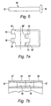
- the locking means comprises a tapered pin 40 as shown in figure 6.
- it may have a head portion 41 to limit excessive movement of the pin into apertures and thereby avoid excessive interference fit forces.
- the taper is 0.02 mm per cm relative to the longitudinal axis of the pin.
- the pin also has a tail portion 42 which lies slightly exposed beyond a lug 25,26 in the assembled condition whereby the pin can be drifted out from the apertures by tapping of the tail part.
- Figures 7a and 7b show a modification of the embodiment of figures 2 to 5 in which apertures in the lugs are tapered (tapers not shown to scale) and arranged to receive a taper pin of corresponding taper angle.
- Figure 7a shows that the outer lugs 95,95' have tapered apertures 97 which taper with reducing diameter in a direction towards aligned inner tugs 96, 96'.
- Inner tugs 96, 96' have tapered apertures 98 which taper in an opposite direction, and with reducing diameter, towards the respective aligned outer lugs 95, 95'.
- the maximum diameter of the apertures 98 equals the minimum diameter of the apertures 97 and hence, as shown in figure 7b, when two of the pieces of figure 7a are assembled together to form two series of aligned apertures, in each series an adjacent pair of inner and outer lugs defines a through-passage zone in which a taper pin can firmly locate.
Landscapes
- Engineering & Computer Science (AREA)
- General Engineering & Computer Science (AREA)
- Mechanical Engineering (AREA)
- Mutual Connection Of Rods And Tubes (AREA)
- Quick-Acting Or Multi-Walled Pipe Joints (AREA)
- Coupling Device And Connection With Printed Circuit (AREA)
- Paper (AREA)
- Mechanical Coupling Of Light Guides (AREA)
- Details Of Connecting Devices For Male And Female Coupling (AREA)
- Mechanical Operated Clutches (AREA)
Claims (11)
- Zusatz-Anschlusseinrichtungsaufbau umfassend zwei Anschlussstücke (20) und ein verriegelndes Element (40), wobei jedes Anschlussstück einen ersten Rumpfbereich (23) aufweist, welcher eine Ausnehmungsgestaltung (24) zur Aufnahme eines Teiles des äusseren Umfangs eines länglichen ersten festen Elements eines strukturellen Aufbaus begrenzt, und wobei zumindest eines der Anschlussstücke einen zweiten Rumpfbereich (22) aufweist, welcher an einem zweiten festen Element befestigbar ist, dessen Anschliessen an dem strukturellen Aufbau erforderlich ist, wobei zumindest eines der Anschlussstücke ein Sicherungsmittel (30) zum Verriegeln der zusammengebauten Anschlussstücke an das erste feste Element umfasst, wobei die zwei Anschlussstücke (20) beide zumindest eine Kantengestaltung (26) an einer Kante der Ausnehmungsgestaltung (24) aufweisen, wobei die zumindest eine Kantengestaltung mit einer Öffnung (27) versehen ist, welche bei der Verwendung sich im wesentlich parallel zu der Längsrichtung des länglichen ersten Elements erstreckt und wobei jeweilige Kantengestaltungen der zwei Anschlussstücke bei der Verwendung ausgerichtet sind, um das verriegelnde Element (40) aufzunehmen, welches sich durch die somit ausgerichteten Öffnungen (27) erstreckt, dadurch gekennzeichnet, dass das verriegelnde Element ein zulaufender Stift (40) ist, welcher einen Presssitz in zumindest einer der ausgerichteten Öffnungen (27) bildet, wobei das Rückhaltemittel (30) dahingehend einsetzbar ist, gleichzeitig die zusammengebauten Anschlussstücke an dem ersten festen Element zu verriegeln und den zulaufenden Stift (40) scherend zu beanspruchen.
- Zusatz-Anschlusseinrichtungsaufbau gemäss Anspruch 1 dadurch gekennzeichnet, dass die Öffnungen (27) frei von einer Schraubgewindegestaltung sind.
- Zusatz-Anschlusseinrichtungsaufbau gemäss Anspruch 1 oder Anspruch 2, dadurch gekennzeichnet, dass die Öffnungen (27) von der Art glatter Bohrungen sind.
- Zusatz-Anschlusseinrichtungsaufbau gemäss irgendeinem der vorhergehenden Ansprüche, dadurch gekennzeichnet, dass in der Verwendung das kleinere der zwei Enden des zulaufenden Stiftes (40) sich axial nach aussen aus einer Öffnung (27) erstreckt.
- Zusatz-Anschlusseinrichtungsaufbau gemäss irgendeinem der Ansprüche 1 bis 3, dadurch gekennzeichnet, dass bei der Verwendung der zulaufende Stift (40) im wesentlichen vollständig innerhalb der Länge der ausgerichteten Öffnungen (27) liegt.
- Zusatz-Anschlusseinrichtungsaufbau gemäss irgendeinem der vorhergehenden Ansprüche dadurch gekennzeichnet, dass das Material des zulaufenden Stiftes (40) eine Härte aufweist, welche geringer als die des Materials ist, welche die Öffnungen (27) der Anschlussstücke begrenzt.
- Zusatz-Anschlusseinrichtungsaufbau gemäss irgendeinem der vorhergehenden Ansprüche dadurch gekennzeichnet, dass die Öffnungen (27) zylindrisch sind.
- Zusatz-Anschlusseinrichtungsaufbau gemäss irgendeinem der Ansprüche 1 bis 6, dadurch gekennzeichnet, dass die benachbarten Kantengestaltungen bei der Verwendung alle mehr als zwei ausgerichtete Öffnungen (27) umfassen, wobei zwei oder mehr aufeinanderfolgende ausgerichtete Öffnungen bei der Verwendung zulaufend sind und angeordnet sind, um eine Durchgangszone von gleichförmig zulaufendem Querschnitt bereitzustellen, und wobei der zulaufende Stift (40) in dichter Passung in zumindest zwei der aufeinanderfolgenden ausgerichteten Öffnungen vorliegt.
- Zusatz-Anschlusseinrichtungsaufbau gemäss irgendeinem der Ansprüche 1 bis 6, dadurch gekennzeichnet, dass der Aufbau zwei Anschlussstücke (20) von einer Art umfasst, welche relativ zueinander in mehr als einer Konfiguration gekoppelt werden können, und wobei in jeder relativen Konfiguration einige, aber nicht alle, der aufeinanderfolgenden ausgerichteten Öffnungen (97, 98) gleichförmig zulaufen, wobei jede Kantengestaltung ein Paar von Ausgerichteten Öffnungen (95, 96, 95', 96') aufweist, welche in dem Aufbau interdigitiert mit den Öffnungen einer benachbarten Kante des anderen Anschlussstückes liegen, wodurch in jeder der Konfigurationen zwei der aufeinanderfolgenden ausgerichteten Öffnungen (97, 98) eine Durchgangszone bereitstellt, welche gleichförmig zuläuft.
- Verfahren zum Bilden einer strukturellen Zwischenverbindung zwischen zwei festen Elementen, umfassend Verwendung eines Zusatzanschluss-Einrichtungsaufbaus, welcher zwei Anschlussstücke (20) und ein verriegelnde Element (40) umfasst, wobei jedes Anschlussstück einen ersten Rumpfbereich (23) aufweist, welcher eine Ausnehmungsgestaltung (24) zur Aufnahme eines Teils des äusseren Umfangs eines länglichen ersten festen Elements begrenzt, welches an ein zweites festes Element zu koppeln ist, wobei zumindest eines der Anschlussstücke (20) einen zweiten Rumpfbereich (22) umfasst, welcher an das zweite feste Element befestigbar ist, wobei die zwei Anschlussstücke beide zumindest eine Kantengestaltung (26) an der Kante der Ausnehmungsgestaltung (24) aufweisen, wobei zumindest eine Kantengestaltung mit einer Öffnung (27) versehen ist, welche bei der Verwendung sich im wesentlich parallel zu der Längsrichtung des länglichen ersten festen Element erstreckt, wobei Öffnungen der jeweiligen Kantengestaltungen der zwei Anschlussstücke bei der Verwendung ausgerichtet sind, um das verriegelnde Element (40) aufzunehmen, und ein Rückhaltemittel (30) umfasst, welches zu einem der Anschlussstücke gehört und zum Befestigen des zusammengebauten Paares von Anschlussstücken in Position relativ zu dem ersten festen Element verwendbar ist, dadurch gekennzeichnet, dass das Verfahren umfasst Vorsehen eines zulaufenden Stiftes, welcher als das Verriegelungselement (40) dient, erstes Verwenden des verriegelnde Elements (40), um eine Zwischenverbindung der Anschlussstücke ohne Erzeugen irgendeiner wesentlichen axialen Vorbelastung zwischen den Anschlussstücken in der Längsrichtung bereitzustellen, und dann gleichzeitiges Verwenden des Rückhaltemittels (30), um die zusammengebauten Anschlussstücke (20) relativ zu dem ersten festen Element zu befestigen und Ausüben einer Scherbelastung auf das verriegelnde Element (40).
- Verfahren gemäss Anspruch 10, dadurch gekennzeichnet, dass es die Verwendung eines zulaufenden Stiftes (40) umfasst, welcher bei anfänglichem Aufbau in nur einer der ausgerichteten Öffnungen (27) in enger Passung vorliegt, wodurch sich diese erweitert.
Applications Claiming Priority (2)
| Application Number | Priority Date | Filing Date | Title |
|---|---|---|---|
| GB9824835 | 1998-11-13 | ||
| GB9824835A GB2343702B (en) | 1998-11-13 | 1998-11-13 | Connector device assembly |
Publications (3)
| Publication Number | Publication Date |
|---|---|
| EP1001176A2 EP1001176A2 (de) | 2000-05-17 |
| EP1001176A3 EP1001176A3 (de) | 2002-01-02 |
| EP1001176B1 true EP1001176B1 (de) | 2005-04-27 |
Family
ID=10842348
Family Applications (1)
| Application Number | Title | Priority Date | Filing Date |
|---|---|---|---|
| EP99308996A Expired - Lifetime EP1001176B1 (de) | 1998-11-13 | 1999-11-11 | Kupplungsanordnung |
Country Status (6)
| Country | Link |
|---|---|
| US (1) | US6602017B2 (de) |
| EP (1) | EP1001176B1 (de) |
| AT (1) | ATE294334T1 (de) |
| CA (1) | CA2289862C (de) |
| DE (1) | DE69924945T2 (de) |
| GB (1) | GB2343702B (de) |
Families Citing this family (5)
| Publication number | Priority date | Publication date | Assignee | Title |
|---|---|---|---|---|
| US7567953B2 (en) * | 2002-03-01 | 2009-07-28 | Business Objects Americas | System and method for retrieving and organizing information from disparate computer network information sources |
| US7578109B2 (en) * | 2004-08-31 | 2009-08-25 | Gossamer Space Frames | Space frames and connection node arrangement for them |
| ES2319599B1 (es) * | 2007-01-08 | 2010-01-26 | Guillermo Petri Larrea | Sistema reversible de seccionamiento en varias piezas de palas de aerogeneradores. |
| US9174429B2 (en) * | 2011-10-26 | 2015-11-03 | Hewlett-Packard Development Company, L.P. | Method and system for the production of frame structure for printing presses |
| US20240049679A1 (en) * | 2022-08-12 | 2024-02-15 | EZwhelp, Inc. | Rail connectors and spacers for animal whelping containers |
Family Cites Families (13)
| Publication number | Priority date | Publication date | Assignee | Title |
|---|---|---|---|---|
| US2291078A (en) * | 1940-08-21 | 1942-07-28 | Frederic R Harris | Floating dry dock |
| GB552105A (en) * | 1942-03-27 | 1943-03-23 | George Harry Gascoigne | Improvements relating to securing devices for tubular structures |
| US3437180A (en) * | 1967-06-27 | 1969-04-08 | Universal Railway Devices Co | Two-way automatic brake adjuster |
| US3737180A (en) * | 1971-03-22 | 1973-06-05 | Kurier Corp | Pipe clamp |
| US4266578A (en) * | 1976-04-23 | 1981-05-12 | Regal Tool & Rubber Co., Inc. | Drill pipe protector |
| FR2395372A1 (fr) * | 1977-06-23 | 1979-01-19 | Mills Echafaudages | Perfectionnements apportes aux elements d'assemblage, notamment pour echafaudages |
| US4219081A (en) * | 1978-11-03 | 1980-08-26 | Halliburton Services | Knockdown centralizer |
| US4580922A (en) * | 1984-12-17 | 1986-04-08 | General Electric Co. | Vertex fittings derived from a master fitting |
| US4864795A (en) | 1987-05-22 | 1989-09-12 | Uni Corp. | Structural framework system and clamp assembly |
| US4932807A (en) * | 1988-07-28 | 1990-06-12 | The United States Of America As Represented By The Administrator Of The National Aeronautics And Space Administration | Clevis joint for deployable space structures |
| GB2227050A (en) * | 1989-01-17 | 1990-07-18 | Michael Derek Merry | Connector |
| US5709500A (en) * | 1995-04-25 | 1998-01-20 | Mizelle; Ned W. | Furniture, furniture manufacturing method, and connector assembly |
| GB2316121B (en) * | 1996-08-07 | 2001-03-14 | Kee Klamp Ltd | Connector device |
-
1998
- 1998-11-13 GB GB9824835A patent/GB2343702B/en not_active Expired - Lifetime
-
1999
- 1999-11-11 AT AT99308996T patent/ATE294334T1/de not_active IP Right Cessation
- 1999-11-11 EP EP99308996A patent/EP1001176B1/de not_active Expired - Lifetime
- 1999-11-11 DE DE69924945T patent/DE69924945T2/de not_active Expired - Lifetime
- 1999-11-15 US US09/439,345 patent/US6602017B2/en not_active Expired - Lifetime
- 1999-11-15 CA CA002289862A patent/CA2289862C/en not_active Expired - Lifetime
Also Published As
| Publication number | Publication date |
|---|---|
| EP1001176A2 (de) | 2000-05-17 |
| DE69924945T2 (de) | 2006-02-23 |
| DE69924945D1 (de) | 2005-06-02 |
| US20020164199A1 (en) | 2002-11-07 |
| GB2343702B (en) | 2002-12-11 |
| CA2289862A1 (en) | 2000-05-13 |
| US6602017B2 (en) | 2003-08-05 |
| CA2289862C (en) | 2008-05-20 |
| GB9824835D0 (en) | 1999-01-06 |
| GB2343702A (en) | 2000-05-17 |
| EP1001176A3 (de) | 2002-01-02 |
| ATE294334T1 (de) | 2005-05-15 |
Similar Documents
| Publication | Publication Date | Title |
|---|---|---|
| US4344719A (en) | Internally expanding railing coupling | |
| US4684280A (en) | Clevis connection | |
| JP4991994B2 (ja) | 形材要素連結体 | |
| US4523338A (en) | Demountable joint | |
| GB2269645A (en) | Connector for connecting two tubes | |
| US20090199365A1 (en) | Stepped pin assembly for an axle and method therefor | |
| CA1296158C (en) | Support leg joint construction with bracing | |
| RU2281422C2 (ru) | Соединение вала | |
| EP0131370A1 (de) | Klemmverbindung | |
| CA2289862C (en) | Connector device assembly | |
| EP2478230B1 (de) | System und verfahren für die starre verbindung von tafeln | |
| US5908260A (en) | Connector device | |
| US4865138A (en) | Drill string stabilizer | |
| US20020172551A1 (en) | Tube connector | |
| US6471594B2 (en) | Flexible all-steel shaft coupling | |
| US5573346A (en) | Tube and connector combination | |
| GB2104997A (en) | Builders scaffolding | |
| KR19980057459U (ko) | 파이프 십자 결속용 고리 고정구 | |
| JP2655132B2 (ja) | 円筒部材の支持金具 | |
| JP7778681B2 (ja) | コンクリートアンカーとともに使用するための回転吊り下げポイント | |
| US6779941B2 (en) | Connector device | |
| RU2031263C1 (ru) | Стопорное устройство | |
| JPS6229690Y2 (de) | ||
| JPH03562Y2 (de) | ||
| JP2512365B2 (ja) | セグメントの連結構造 |
Legal Events
| Date | Code | Title | Description |
|---|---|---|---|
| PUAI | Public reference made under article 153(3) epc to a published international application that has entered the european phase |
Free format text: ORIGINAL CODE: 0009012 |
|
| AK | Designated contracting states |
Kind code of ref document: A2 Designated state(s): AT BE CH CY DE DK ES FI FR GB GR IE IT LI LU MC NL PT SE |
|
| AX | Request for extension of the european patent |
Free format text: AL;LT;LV;MK;RO;SI |
|
| PUAL | Search report despatched |
Free format text: ORIGINAL CODE: 0009013 |
|
| AK | Designated contracting states |
Kind code of ref document: A3 Designated state(s): AT BE CH CY DE DK ES FI FR GB GR IE IT LI LU MC NL PT SE |
|
| AX | Request for extension of the european patent |
Free format text: AL;LT;LV;MK;RO;SI |
|
| 17P | Request for examination filed |
Effective date: 20020613 |
|
| AKX | Designation fees paid |
Free format text: AT BE CH CY DE DK ES FI FR GB GR IE IT LI LU MC NL PT SE |
|
| 17Q | First examination report despatched |
Effective date: 20030718 |
|
| GRAP | Despatch of communication of intention to grant a patent |
Free format text: ORIGINAL CODE: EPIDOSNIGR1 |
|
| GRAS | Grant fee paid |
Free format text: ORIGINAL CODE: EPIDOSNIGR3 |
|
| GRAA | (expected) grant |
Free format text: ORIGINAL CODE: 0009210 |
|
| RBV | Designated contracting states (corrected) |
Designated state(s): AT BE CH CY DE DK ES FI FR GR IE IT LI LU MC NL PT SE |
|
| AK | Designated contracting states |
Kind code of ref document: B1 Designated state(s): AT BE CH CY DE DK ES FI FR GR IE IT LI LU MC NL PT SE |
|
| PG25 | Lapsed in a contracting state [announced via postgrant information from national office to epo] |
Ref country code: LI Free format text: LAPSE BECAUSE OF FAILURE TO SUBMIT A TRANSLATION OF THE DESCRIPTION OR TO PAY THE FEE WITHIN THE PRESCRIBED TIME-LIMIT Effective date: 20050427 Ref country code: IT Free format text: LAPSE BECAUSE OF FAILURE TO SUBMIT A TRANSLATION OF THE DESCRIPTION OR TO PAY THE FEE WITHIN THE PRESCRIBED TIME-LIMIT;WARNING: LAPSES OF ITALIAN PATENTS WITH EFFECTIVE DATE BEFORE 2007 MAY HAVE OCCURRED AT ANY TIME BEFORE 2007. THE CORRECT EFFECTIVE DATE MAY BE DIFFERENT FROM THE ONE RECORDED. Effective date: 20050427 Ref country code: FI Free format text: LAPSE BECAUSE OF FAILURE TO SUBMIT A TRANSLATION OF THE DESCRIPTION OR TO PAY THE FEE WITHIN THE PRESCRIBED TIME-LIMIT Effective date: 20050427 Ref country code: CH Free format text: LAPSE BECAUSE OF FAILURE TO SUBMIT A TRANSLATION OF THE DESCRIPTION OR TO PAY THE FEE WITHIN THE PRESCRIBED TIME-LIMIT Effective date: 20050427 Ref country code: BE Free format text: LAPSE BECAUSE OF FAILURE TO SUBMIT A TRANSLATION OF THE DESCRIPTION OR TO PAY THE FEE WITHIN THE PRESCRIBED TIME-LIMIT Effective date: 20050427 Ref country code: AT Free format text: LAPSE BECAUSE OF FAILURE TO SUBMIT A TRANSLATION OF THE DESCRIPTION OR TO PAY THE FEE WITHIN THE PRESCRIBED TIME-LIMIT Effective date: 20050427 |
|
| RAP1 | Party data changed (applicant data changed or rights of an application transferred) |
Owner name: KEE KLAMP LIMITED |
|
| REG | Reference to a national code |
Ref country code: CH Ref legal event code: EP |
|
| REG | Reference to a national code |
Ref country code: IE Ref legal event code: FG4D |
|
| REF | Corresponds to: |
Ref document number: 69924945 Country of ref document: DE Date of ref document: 20050602 Kind code of ref document: P |
|
| PG25 | Lapsed in a contracting state [announced via postgrant information from national office to epo] |
Ref country code: SE Free format text: LAPSE BECAUSE OF FAILURE TO SUBMIT A TRANSLATION OF THE DESCRIPTION OR TO PAY THE FEE WITHIN THE PRESCRIBED TIME-LIMIT Effective date: 20050727 Ref country code: GR Free format text: LAPSE BECAUSE OF FAILURE TO SUBMIT A TRANSLATION OF THE DESCRIPTION OR TO PAY THE FEE WITHIN THE PRESCRIBED TIME-LIMIT Effective date: 20050727 Ref country code: DK Free format text: LAPSE BECAUSE OF FAILURE TO SUBMIT A TRANSLATION OF THE DESCRIPTION OR TO PAY THE FEE WITHIN THE PRESCRIBED TIME-LIMIT Effective date: 20050727 |
|
| PG25 | Lapsed in a contracting state [announced via postgrant information from national office to epo] |
Ref country code: ES Free format text: LAPSE BECAUSE OF FAILURE TO SUBMIT A TRANSLATION OF THE DESCRIPTION OR TO PAY THE FEE WITHIN THE PRESCRIBED TIME-LIMIT Effective date: 20050807 |
|
| PG25 | Lapsed in a contracting state [announced via postgrant information from national office to epo] |
Ref country code: PT Free format text: LAPSE BECAUSE OF FAILURE TO SUBMIT A TRANSLATION OF THE DESCRIPTION OR TO PAY THE FEE WITHIN THE PRESCRIBED TIME-LIMIT Effective date: 20051010 |
|
| REG | Reference to a national code |
Ref country code: CH Ref legal event code: PL |
|
| PG25 | Lapsed in a contracting state [announced via postgrant information from national office to epo] |
Ref country code: CY Free format text: LAPSE BECAUSE OF FAILURE TO SUBMIT A TRANSLATION OF THE DESCRIPTION OR TO PAY THE FEE WITHIN THE PRESCRIBED TIME-LIMIT Effective date: 20051111 |
|
| PG25 | Lapsed in a contracting state [announced via postgrant information from national office to epo] |
Ref country code: MC Free format text: LAPSE BECAUSE OF NON-PAYMENT OF DUE FEES Effective date: 20051130 Ref country code: LU Free format text: LAPSE BECAUSE OF NON-PAYMENT OF DUE FEES Effective date: 20051130 |
|
| PLBE | No opposition filed within time limit |
Free format text: ORIGINAL CODE: 0009261 |
|
| STAA | Information on the status of an ep patent application or granted ep patent |
Free format text: STATUS: NO OPPOSITION FILED WITHIN TIME LIMIT |
|
| ET | Fr: translation filed | ||
| 26N | No opposition filed |
Effective date: 20060130 |
|
| REG | Reference to a national code |
Ref country code: FR Ref legal event code: PLFP Year of fee payment: 17 |
|
| REG | Reference to a national code |
Ref country code: FR Ref legal event code: PLFP Year of fee payment: 18 |
|
| REG | Reference to a national code |
Ref country code: FR Ref legal event code: PLFP Year of fee payment: 19 |
|
| PGFP | Annual fee paid to national office [announced via postgrant information from national office to epo] |
Ref country code: IE Payment date: 20180918 Year of fee payment: 20 |
|
| PGFP | Annual fee paid to national office [announced via postgrant information from national office to epo] |
Ref country code: NL Payment date: 20180927 Year of fee payment: 20 |
|
| PGFP | Annual fee paid to national office [announced via postgrant information from national office to epo] |
Ref country code: DE Payment date: 20181130 Year of fee payment: 20 |
|
| PGFP | Annual fee paid to national office [announced via postgrant information from national office to epo] |
Ref country code: FR Payment date: 20181129 Year of fee payment: 20 |
|
| REG | Reference to a national code |
Ref country code: DE Ref legal event code: R071 Ref document number: 69924945 Country of ref document: DE |
|
| REG | Reference to a national code |
Ref country code: NL Ref legal event code: MK Effective date: 20191110 |
|
| REG | Reference to a national code |
Ref country code: IE Ref legal event code: MK9A |
|
| PG25 | Lapsed in a contracting state [announced via postgrant information from national office to epo] |
Ref country code: IE Free format text: LAPSE BECAUSE OF EXPIRATION OF PROTECTION Effective date: 20191111 |