EP1001195A1 - Dichtungsanordnung, insbesondere für Turbogeneratoren - Google Patents
Dichtungsanordnung, insbesondere für Turbogeneratoren Download PDFInfo
- Publication number
- EP1001195A1 EP1001195A1 EP98121290A EP98121290A EP1001195A1 EP 1001195 A1 EP1001195 A1 EP 1001195A1 EP 98121290 A EP98121290 A EP 98121290A EP 98121290 A EP98121290 A EP 98121290A EP 1001195 A1 EP1001195 A1 EP 1001195A1
- Authority
- EP
- European Patent Office
- Prior art keywords
- sealing
- seal assembly
- supply
- seal
- chamber
- Prior art date
- Legal status (The legal status is an assumption and is not a legal conclusion. Google has not performed a legal analysis and makes no representation as to the accuracy of the status listed.)
- Withdrawn
Links
- 238000007789 sealing Methods 0.000 claims abstract description 155
- 239000012530 fluid Substances 0.000 claims abstract description 40
- 239000001257 hydrogen Substances 0.000 description 15
- 229910052739 hydrogen Inorganic materials 0.000 description 15
- UFHFLCQGNIYNRP-UHFFFAOYSA-N Hydrogen Chemical compound [H][H] UFHFLCQGNIYNRP-UHFFFAOYSA-N 0.000 description 13
- 239000007789 gas Substances 0.000 description 12
- 239000000314 lubricant Substances 0.000 description 4
- 150000002431 hydrogen Chemical class 0.000 description 3
- 229910001369 Brass Inorganic materials 0.000 description 2
- 229910000831 Steel Inorganic materials 0.000 description 2
- 239000010951 brass Substances 0.000 description 2
- 238000010276 construction Methods 0.000 description 2
- 239000002826 coolant Substances 0.000 description 2
- 238000007599 discharging Methods 0.000 description 2
- 229920001971 elastomer Polymers 0.000 description 2
- 239000010959 steel Substances 0.000 description 2
- 229910000838 Al alloy Inorganic materials 0.000 description 1
- 229910000906 Bronze Inorganic materials 0.000 description 1
- 229910001018 Cast iron Inorganic materials 0.000 description 1
- 229910000881 Cu alloy Inorganic materials 0.000 description 1
- 239000004809 Teflon Substances 0.000 description 1
- 229920006362 Teflon® Polymers 0.000 description 1
- 229910001361 White metal Inorganic materials 0.000 description 1
- 239000010974 bronze Substances 0.000 description 1
- 238000004891 communication Methods 0.000 description 1
- 238000001816 cooling Methods 0.000 description 1
- KUNSUQLRTQLHQQ-UHFFFAOYSA-N copper tin Chemical compound [Cu].[Sn] KUNSUQLRTQLHQQ-UHFFFAOYSA-N 0.000 description 1
- 238000002347 injection Methods 0.000 description 1
- 239000007924 injection Substances 0.000 description 1
- 230000001050 lubricating effect Effects 0.000 description 1
- 238000012423 maintenance Methods 0.000 description 1
- 239000000463 material Substances 0.000 description 1
- 239000002184 metal Substances 0.000 description 1
- 229910052751 metal Inorganic materials 0.000 description 1
- 238000000034 method Methods 0.000 description 1
- 238000012986 modification Methods 0.000 description 1
- 230000004048 modification Effects 0.000 description 1
- 239000004033 plastic Substances 0.000 description 1
- -1 polytetrafluorethylen Polymers 0.000 description 1
- 230000000063 preceeding effect Effects 0.000 description 1
- 238000005086 pumping Methods 0.000 description 1
- 229920006395 saturated elastomer Polymers 0.000 description 1
- 239000007779 soft material Substances 0.000 description 1
- BFKJFAAPBSQJPD-UHFFFAOYSA-N tetrafluoroethene Chemical compound FC(F)=C(F)F BFKJFAAPBSQJPD-UHFFFAOYSA-N 0.000 description 1
- XLYOFNOQVPJJNP-UHFFFAOYSA-N water Substances O XLYOFNOQVPJJNP-UHFFFAOYSA-N 0.000 description 1
- 239000010969 white metal Substances 0.000 description 1
Images

Classifications
-
- F—MECHANICAL ENGINEERING; LIGHTING; HEATING; WEAPONS; BLASTING
- F16—ENGINEERING ELEMENTS AND UNITS; GENERAL MEASURES FOR PRODUCING AND MAINTAINING EFFECTIVE FUNCTIONING OF MACHINES OR INSTALLATIONS; THERMAL INSULATION IN GENERAL
- F16J—PISTONS; CYLINDERS; SEALINGS
- F16J15/00—Sealings
- F16J15/16—Sealings between relatively-moving surfaces
- F16J15/40—Sealings between relatively-moving surfaces by means of fluid
Definitions
- the invention relates to a seal assembly comprising a first sealing member and a second sealing member for sealing a rotatable shaft, in particular for a turbo generator, in which said sealing members being axial spaced apart and axial movable.
- the seal assembly further comprises supply for feeding the sealing fluid.
- Such a sealing assembly is used, for example, on an electrical machine filled with hydrogen, in which the hydrogen is used for cooling purposes.
- the sealing assembly is used in order to seal a leakage path between a rotatable shaft and a stationary casing of a machine and to prevent an escape of hydrogen into the surroundings of the machine.
- the use of the sealing assembly on a large turbo generator which is cooled solely with hydrogen, or with hydrogen and water is of particular importance.
- Such a turbo generator normally has a power output of 200 MVA to 2000 MVA, especially 500 MVA and it has a sealed casing in which hydrogen is under an absolute pressure of 10 5 Pa to 10 6 Pa.
- a shaft seal for hydrogen-cooled turbo generators is described in German published, non-prosecuted patent application DE 37 12 943 A1, corresponding to U.S. patent No. 4,815,748.
- That shaft seal has a sealing configuration which is radially movable in a chamber and has two sealing rings enclosing the shaft, with at least one of the sealing rings being axially movable. Sealing oil is directed from the chamber to the shaft to be sealed through the use of radial channels which run either through one sealing ring or between the two sealing rings.
- the second sealing ring has radial channels which connect the interface between the shaft and the sealing ring to a fluid collecting space. In that way, some of the sealing oil flow is diverted and fed back into the seal assembly thus reducing the quantity of sealing fluid entering the generator.
- WO 97/21948 A1 discloses a sealing system for a turbo generator having a single circuit for a sealing oil.
- a groove opens into the cylindrical recess and defining a first groove surface or flank for holding the sealing ring between the surfaces.
- the first groove surface has an annular groove.
- the configuration further comprises a chamber surrounding the sealing ring which is filled with oil remaining in the groove and directed out of the chamber through the at least one line of the sealing surface.
- annular seal is held in the annular groove and a branch line communicates between the annular groove and the chamber.
- the chamber is filled with the oil used for sealing which penetrates into the existing radial gaps between the holder and the sealing ring. Due to the fact that the radial gap is blocked by the annular seal at the first groove surface to prevent a through flow of the oil, oil from a radial gap can no longer reach the interior of the casing thereby become saturated with hydrogen.
- the annular seal is pressed onto the sealing ring by oil which acts on the annular seal from the chamber through the branch line and the annular groove. In this way the quantity of oil flowing into the generator is reduced.
- GB 2 133 482 B discloses an annular seal assembly for use with rotary members, particularly an assembly for minimizing hydrogen leakage past the rotor shaft of the turbine generator set.
- the seal assembly comprises a rotatable shaft having a journal, a non-rotary annular seal member, which fits around the journal, having on opposite sides radially-extending plain annular faces.
- the annular sealing member is located in an annular chamber in a housing which is arranged about the journal and which is in two relatively axially slidable parts. These slidable parts have radially-extending plain annular surfaces in sliding engagement with respective annular faces of the seal member.
- Said parts are also in relatively sealed relationships so as to close the annular chamber and being forced towards one another by biasing means to force the annular surface of the parts against respective annular faces of the seal member.
- the seal member having a cylindrical inner seal surface interrupted by a circumferential groove and having channels interconnecting the chamber and the groove.
- the assembly also comprises means to admit lubricant to the chamber at a pressure greater than the pressure externaly to the assembly to cause lubricant to flow through said channels into the groove and between the seal member and the journal.
- the lubricant is also lubricating the faces of the seal member and the surfaces of the housing parts.
- the housing consists of three annular parts of steel or other suitable metal, e.g. cast iron or brass.
- U.S. patent 3,999,766 discloses a gas cooled dynamoelectric machine comprising sealing means at each end of the machine to prevent the axial leakage of gas coolant out of the machine along the rotor surface.
- the sealing means comprise an annular holder at each end of the machine, each holder having resiliently mounted therein a pair of sealing rings spaced apart in the axial direction to define an oil feed annulus there between. Seal oil is supplied to the oil feed annulus at a higher pressure than the gas cooled pressure thereby sealing the gas coolant into the machine.
- a hydraulic fluid, usually oil is supplied to the oil feed annulus through an oil inlet conduit in the annular holder.
- the oil feed annulus is in fluid communication with the rotor surface whereby the annular clearance between the sealing means and the rotor surface are supplied with hydraulic fluid to form a fluid seal.
- a similar sealing assembly is disclosed in DE 31 18 469.Said sealing assembly comprises two sealing rings enclosing a rotor shaft and being mounted in a holder. The sealing rings are spaced apart in the axial direction by a spring to define an oil feed annulus therebetween. Through the spring a radial inwardly directed force as well as an axial directed force is applied on the two sealing rings, so that they are pressed against the inner surface of the holder.
- an annular seal is provided, in particular an annular lip seal or a rubber seal ring to reduce oil flow through a remaining clearance between the inner surface of the holder and the surface of the adjacent sealing ring.
- a seal assembly comprises a first sealing member and a second sealing member for sealing a rotatable shaft, said sealing members being axial spaced apart and axially movable, further comprising a supply for feeding (discharging) a sealing fluid between said sealing members, said supply opening in an axial gap between said sealing members.
- the seal assembly is in particular useful for a gas seal for rotating shaft by minimizing consumption of the sealing fluid, e.g. a hydraulic fluid like oil, without the use of sliding non-metalic seals or springs. It could be preferably used as double ring hydrogen seal in a hydrogen cooled turbogenerator.
- a gap e.g. a conduit
- Sealing fluid is fed directly into this gap by the sealing fluid supply opening directly in said gap.
- the sealing fluid which is directly fed into the gap causes a hydraulic force in the axial direction on the surface of the sealing members by which the sealing rings are spaced apart to form said gap.
- said supply for feeding a sealing fluid is formed as a separate ring (oil feedring) through which sealing fluid (oil) is discharged into said gap.
- the supply allows an injection of sealing fluid to a position near the shaft surface, so that the resulting hydraulic force separates the seal rings in axial direction under all operating conditions.
- the seal assembly comprises a sealing chamber in which said sealing members, in particular sealing rings, are located.
- This sealing chamber could be formed by two housing parts which are joined in the axial direction. The two housing parts may be joined so that they are still separable. These two housing parts form a holder for the sealing members.
- Said sealing chamber has a chamber wall adjacent to one of said sealing members. Due to the hydraulic force caused by the sealing fluid directly fed into the gap between the sealing members, the sealing members are pressed against the wall of the chamber.
- the geometry of the sealing members is preferably arranged in a way that the sealing rings are pressed against the walls of the chamber with such a pressure that a minimum leakage of sealing fluid between the walls and the sealing members occurs whilst allowing the rings to follow the lateral movement of the shaft.
- said sealing member has an inner radius enclosing said shaft and said supply opens on a supply radius which is greater than said inner radius, for example more than 1.0 mm.
- the clearance between the rotatable shaft and the supply is greater than the clearance between the sealing member and the rotatable shaft.
- said first and/or second sealing member comprises at least two part-circular parts secured together in such a way that they are still separable. It is also possible that the holder, in particular said two housing parts forming the sealing chamber, comprises also at least two part-circular parts secured together. In this case, the parts of the seal assembly are very easily joint together which is advantageous maintenance.
- the seal assembly is part of a rotating machine, in particular a dynamoelectric machine.
- Said rotational machine is preferably a gas cooled turbogenerator.
- Such a turbogenerator may have an electrical output from 200 MVA to about 2000 MVA electric. Typical shaft speeds are between 1500 and 3600 revolutions per minute (rpm).
- the sealing member and/or the housing parts forming the sealing chamber are preferably made of steel, brass, aluminium alloy, bronze, copper alloy or plastic.
- this material can have a low coefficient of friction, like polytetrafluorethylen, such as TEFLON, which is a trade mark of Dupont.
- TEFLON polytetrafluorethylen
- the sealing member can be faced with a soft material, for example white metal.
- a machine comprising a casing, a shaft mounted at least partly within the casing for rotation relatively thereto and a seal assembly as described in the preceeding paragraphs is provided for sealing the shaft relative to the casing is provided.
- FIG 1 a central longitudinal section of a machine, in particular a turbo-generator 11, is shown.
- Said machine 11 comprises a partly shown casing 17 and a shaft 12 which extends out of said machine casing 17, in which hydrogen circulates. Between said casing 17 and the shaft 12, a longitudinal extending gap 15 (radial gap) remains.
- a seal assembly 1 is provided so that no hydrogen is discharged through the radial gap 15 into the atmosphere that surrounds the machine 11 (air side 20).
- Said seal assembly 1 comprises a first sealing member 2 adjacent to the hydrogen side 21 (gas side sealing ring 2) and a second sealing member 3 adjacent to the air side 20 (air side sealing ring 3).
- Said sealing members 2, 3 enclose the shaft 12.
- the sealing members 2, 3 have an inner radius RI, being of the order of 0.05 mm to 0.8 mm greater than the radius of the shaft 12.
- the radius of the shaft for a large turbogenerator is about 150 mm to 400 mm.
- the two sealing members 2 and 3 are situated in a sealing chamber 6 which is formed by a first housing part 7A which is part of the machine casing 17 and a second housing part 7B.
- the second housing part 7B is ringlike and separable from the casing 17. It is secured to the first housing part 7A by a number of bolts (only one of the bolts 8 is shown in figure 1).
- Sealing members 2 and 3 are axial movable and axial spaced apart, forming an axial gap 5 between them.
- a ringlike supply 4 for feeding sealing fluid 14 extends in radial direction inwardly.
- the fluid 14 is supplied via radial channels in said supply ring 4 with supply outlets 4B in the gap 5.
- the supply outlets 4B open in the gap 5 at a radius RS which is near to the shaft 12 but greater than the inner radius RI of sealing member 2 or 3.
- the supply ring 4 is separably mounted between the housing parts 7A, 7B forming the seal chamber 6.
- Said supply outlet 4B is connected with the supply chamber 19 formed between said supply ring 4 and the first housing part 7A for discharging the sealing fluid 14, for example oil or any other adequate lubricant, to the gap 5.
- Said seal chamber 6 has two chamber walls 18, formed by the first housing part 7A and the second housing part 7B as well as a chamber ceiling 16 formed by the first housing part 7A.
- Chamber walls 18 have recesses so that sealing surfaces 10 are formed which are in close contact with the sealing members 2 and 3, respectively.
- radial directed grooves are provided in the recesses of at least one of the chamber walls 18 . Due to these grooves and the geometry of the sealing members an adequate pressure for minimizing leakage between the chamber walls 18 and the sealing members 2 and 3 respectively is established. It is also possible to lubricate the surfaces of the sealing rings 2 and 3 adjacent to the chamber walls 18 with the grooves which are filled with sealing fluid 14.
- the grooves 9 may be directed radially or in circumferential direction.
- the distance between the sealing surfaces 10 of the first housing part 7A and the second housing part 7B is approximately 80 mm and the over-all-width of the first housing part 7A and the second housing part 7B comprising the seal assembly 1 is about 130 mm.
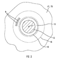
- Figure 2 shows a cross sectional view through the housing part 7A between the chamber ceiling 16 and the rotational axis 13 of the shaft 12. For simplicity only some of the grooves 9 are shown, in the radial direction. The grooves 9 extend between the chamber ceiling 16 and the sealing surface 10.
- sealing fluid 14 is discharged through the supply outlet 4B in the axial gap 5.
- the sealing fluid 14 is supplied at a pressure which is sufficiently higher than the gas pressure of the hydrogen inside the machine 11, to prevent gas leakage between the sealing chamber 2, the housing wall 18 and the shaft 12.
- the fluid supply to chamber 19 is from an auxiliary system of pumps, coolers and control valves which is not shown.
- the pressure of the hydrogen gas is about 500 kPa (absolute) and the pressure of sealing fluid, in particular oil, is about 0.5 x 10 5 Pa to 1.5 x 10 5 Pa above that pressure, the difference being controlled by a differential-pressure control valve located in an oil supply pipe (not shown).
- the sealing fluid 14, in particular oil, flowing from the seal assembly 1 along the shaft 12 in the direction of the air side or the gas side is collected by special collecting means like rings and labyrinth seals and returned to a seal fluid reservoir (oil sump) not shown.
- a seal fluid reservoir oil sump
- the spirit of the invention is not restricted to the example shown.
- the supply 4 for feeding a sealing fluid 14 is integrated either in one of the housing parts 7A, 7B or in one of the sealing members 2 or 3.
Landscapes
- Engineering & Computer Science (AREA)
- General Engineering & Computer Science (AREA)
- Mechanical Engineering (AREA)
- Sealing Using Fluids, Sealing Without Contact, And Removal Of Oil (AREA)
Priority Applications (1)
| Application Number | Priority Date | Filing Date | Title |
|---|---|---|---|
| EP98121290A EP1001195A1 (de) | 1998-11-09 | 1998-11-09 | Dichtungsanordnung, insbesondere für Turbogeneratoren |
Applications Claiming Priority (1)
| Application Number | Priority Date | Filing Date | Title |
|---|---|---|---|
| EP98121290A EP1001195A1 (de) | 1998-11-09 | 1998-11-09 | Dichtungsanordnung, insbesondere für Turbogeneratoren |
Publications (1)
| Publication Number | Publication Date |
|---|---|
| EP1001195A1 true EP1001195A1 (de) | 2000-05-17 |
Family
ID=8232940
Family Applications (1)
| Application Number | Title | Priority Date | Filing Date |
|---|---|---|---|
| EP98121290A Withdrawn EP1001195A1 (de) | 1998-11-09 | 1998-11-09 | Dichtungsanordnung, insbesondere für Turbogeneratoren |
Country Status (1)
| Country | Link |
|---|---|
| EP (1) | EP1001195A1 (de) |
Cited By (1)
| Publication number | Priority date | Publication date | Assignee | Title |
|---|---|---|---|---|
| CN115143764A (zh) * | 2022-05-27 | 2022-10-04 | 天华化工机械及自动化研究设计院有限公司 | 进料密封结构及回转干燥机 |
Citations (8)
| Publication number | Priority date | Publication date | Assignee | Title |
|---|---|---|---|---|
| US2971783A (en) * | 1957-03-04 | 1961-02-14 | City Nat Bank And Trust Compan | Rotary seal |
| US3462159A (en) * | 1966-06-17 | 1969-08-19 | Bbc Brown Boveri & Cie | Floating-ring type shaft seal |
| US3999766A (en) | 1975-11-28 | 1976-12-28 | General Electric Company | Dynamoelectric machine shaft seal |
| US4486024A (en) * | 1983-05-17 | 1984-12-04 | Westinghouse Electric Corp. | Dual-ring gland seal for dynamoelectric machine rotor |
| GB2133482B (en) | 1983-01-13 | 1986-01-29 | Northern Eng Ind | Seal assembly |
| EP0209999A2 (de) * | 1985-07-13 | 1987-01-28 | John Crane Uk Limited | Dichtung |
| US4815748A (en) | 1987-03-23 | 1989-03-28 | Bbc Brown Boveri Ag | Shaft seal for gas-filled machines |
| WO1997021948A2 (de) | 1995-12-08 | 1997-06-19 | Siemens Aktiengesellschaft | Anordnung zur abdichtung eines durchführungsspaltes zwischen einer wand und einer welle |
-
1998
- 1998-11-09 EP EP98121290A patent/EP1001195A1/de not_active Withdrawn
Patent Citations (8)
| Publication number | Priority date | Publication date | Assignee | Title |
|---|---|---|---|---|
| US2971783A (en) * | 1957-03-04 | 1961-02-14 | City Nat Bank And Trust Compan | Rotary seal |
| US3462159A (en) * | 1966-06-17 | 1969-08-19 | Bbc Brown Boveri & Cie | Floating-ring type shaft seal |
| US3999766A (en) | 1975-11-28 | 1976-12-28 | General Electric Company | Dynamoelectric machine shaft seal |
| GB2133482B (en) | 1983-01-13 | 1986-01-29 | Northern Eng Ind | Seal assembly |
| US4486024A (en) * | 1983-05-17 | 1984-12-04 | Westinghouse Electric Corp. | Dual-ring gland seal for dynamoelectric machine rotor |
| EP0209999A2 (de) * | 1985-07-13 | 1987-01-28 | John Crane Uk Limited | Dichtung |
| US4815748A (en) | 1987-03-23 | 1989-03-28 | Bbc Brown Boveri Ag | Shaft seal for gas-filled machines |
| WO1997021948A2 (de) | 1995-12-08 | 1997-06-19 | Siemens Aktiengesellschaft | Anordnung zur abdichtung eines durchführungsspaltes zwischen einer wand und einer welle |
Cited By (1)
| Publication number | Priority date | Publication date | Assignee | Title |
|---|---|---|---|---|
| CN115143764A (zh) * | 2022-05-27 | 2022-10-04 | 天华化工机械及自动化研究设计院有限公司 | 进料密封结构及回转干燥机 |
Similar Documents
| Publication | Publication Date | Title |
|---|---|---|
| EP1934474B1 (de) | Lagerdichtungsanordung mit labyrinthdichtungs- und schraubdichtungskombination | |
| AU694688B2 (en) | Bearing housing seal | |
| JPH0612145B2 (ja) | ガスタービンエンジンロータ軸受用シール装置 | |
| CA1270026A (en) | Sealing method for bearing assemblies | |
| JPH0137591B2 (de) | ||
| KR20140124422A (ko) | 유체 냉각식 전기 보조 터보차저 | |
| JP4485729B2 (ja) | ターボマシンで軸方向スラストを補償する装置 | |
| US12176797B2 (en) | Electric motor | |
| EP1900079B1 (de) | Wellendichtung fur wasserstoffgekühlter elektrischer stromerzeuger mit ortsunabhängigen rohrkupplung | |
| US20220049710A1 (en) | Compact sliding-contact bearing with a sealing arrangement, and water pump with same | |
| EP0266664B1 (de) | Anordnung von einem Stopfbüchsengehäuse | |
| CA1299211C (en) | Mechanical seal lubrication improvement | |
| CN107407425A (zh) | 用于流体动力机械的密封装置 | |
| EP3784932B1 (de) | Dichtungsanordnung, hydrodynamische maschine und fahrzeug | |
| US12173695B2 (en) | Axial seal for a generator rotor of a wind turbine | |
| US6241490B1 (en) | Multirotor vacuum pump | |
| CN1117232C (zh) | 用于密封箱壁与轴之间套状间隙的装置 | |
| EP0959254B1 (de) | Kreiselpumpe mit Radialdichtring | |
| US5887473A (en) | Continuous extrusion apparatus | |
| US6945759B2 (en) | Engine driven dry air pump with a flange mounted oil drain | |
| US4418920A (en) | Fluid seal for engine crankshaft applications | |
| GB2401730A (en) | Rotor shaft with fluid coolant passages for an electrical machine; a drive axle containing said machine. | |
| RU2107833C1 (ru) | Маслоприемник гидротурбины с поворотными лопастями | |
| CN218177364U (zh) | 一种新型的柱塞液压马达 | |
| GB2133482A (en) | Seal assembly |
Legal Events
| Date | Code | Title | Description |
|---|---|---|---|
| PUAI | Public reference made under article 153(3) epc to a published international application that has entered the european phase |
Free format text: ORIGINAL CODE: 0009012 |
|
| AK | Designated contracting states |
Kind code of ref document: A1 Designated state(s): AT BE CH CY DE DK ES FI FR GB GR IE IT LI LU MC NL PT SE |
|
| AX | Request for extension of the european patent |
Free format text: AL;LT;LV;MK;RO;SI |
|
| AKX | Designation fees paid | ||
| REG | Reference to a national code |
Ref country code: DE Ref legal event code: 8566 |
|
| STAA | Information on the status of an ep patent application or granted ep patent |
Free format text: STATUS: THE APPLICATION IS DEEMED TO BE WITHDRAWN |
|
| 18D | Application deemed to be withdrawn |
Effective date: 20001118 |