EP1001223B1 - Turbine à gaz avec injection du carburant rotatif - Google Patents
Turbine à gaz avec injection du carburant rotatif Download PDFInfo
- Publication number
- EP1001223B1 EP1001223B1 EP99122467A EP99122467A EP1001223B1 EP 1001223 B1 EP1001223 B1 EP 1001223B1 EP 99122467 A EP99122467 A EP 99122467A EP 99122467 A EP99122467 A EP 99122467A EP 1001223 B1 EP1001223 B1 EP 1001223B1
- Authority
- EP
- European Patent Office
- Prior art keywords
- combustion chamber
- fuel
- compressor
- rotor shaft
- gas turbine
- Prior art date
- Legal status (The legal status is an assumption and is not a legal conclusion. Google has not performed a legal analysis and makes no representation as to the accuracy of the status listed.)
- Expired - Lifetime
Links
- 239000000446 fuel Substances 0.000 title claims description 50
- 238000002347 injection Methods 0.000 title description 9
- 239000007924 injection Substances 0.000 title description 9
- 238000002485 combustion reaction Methods 0.000 claims description 45
- 238000005096 rolling process Methods 0.000 claims description 11
- 238000011144 upstream manufacturing Methods 0.000 claims description 11
- 239000007789 gas Substances 0.000 description 27
- 238000009826 distribution Methods 0.000 description 5
- 238000001816 cooling Methods 0.000 description 4
- 238000005461 lubrication Methods 0.000 description 3
- 238000009423 ventilation Methods 0.000 description 3
- 238000005553 drilling Methods 0.000 description 2
- 239000002826 coolant Substances 0.000 description 1
- 239000000314 lubricant Substances 0.000 description 1
- 239000010687 lubricating oil Substances 0.000 description 1
- 238000000034 method Methods 0.000 description 1
- 239000003595 mist Substances 0.000 description 1
- 230000000149 penetrating effect Effects 0.000 description 1
- 238000003860 storage Methods 0.000 description 1
- 239000010409 thin film Substances 0.000 description 1
Images


Classifications
-
- F—MECHANICAL ENGINEERING; LIGHTING; HEATING; WEAPONS; BLASTING
- F01—MACHINES OR ENGINES IN GENERAL; ENGINE PLANTS IN GENERAL; STEAM ENGINES
- F01D—NON-POSITIVE DISPLACEMENT MACHINES OR ENGINES, e.g. STEAM TURBINES
- F01D25/00—Component parts, details, or accessories, not provided for in, or of interest apart from, other groups
- F01D25/18—Lubricating arrangements
-
- F—MECHANICAL ENGINEERING; LIGHTING; HEATING; WEAPONS; BLASTING
- F23—COMBUSTION APPARATUS; COMBUSTION PROCESSES
- F23R—GENERATING COMBUSTION PRODUCTS OF HIGH PRESSURE OR HIGH VELOCITY, e.g. GAS-TURBINE COMBUSTION CHAMBERS
- F23R3/00—Continuous combustion chambers using liquid or gaseous fuel
- F23R3/28—Continuous combustion chambers using liquid or gaseous fuel characterised by the fuel supply
- F23R3/38—Continuous combustion chambers using liquid or gaseous fuel characterised by the fuel supply comprising rotary fuel injection means
Definitions
- the invention relates to a small gas turbine with a radial or Slinger combustion chamber as well as with a radial compressor or diagonal compressor upstream of the radial or Slinger combustion chamber and a turbine part connected to the latter by means of a rotor shaft which runs in the axial direction and is supported by at least one roller bearing, the fuel passing through A delivery pipe provided in the impeller of the radial compressor / diagonal compressor enters an intersection part of the rotor shaft located in the region of the combustion chamber near the compressor and is supplied to the combustion chamber via supply holes running essentially in the radial direction thereof, and in or upstream of the intersection part (s) there is an upstream of the supply holes Centrifugal siphon through which fuel flows is provided.
- a delivery pipe provided in the impeller of the radial compressor / diagonal compressor enters an intersection part of the rotor shaft located in the region of the combustion chamber near the compressor and is supplied to the combustion chamber via supply holes running essentially in the radial direction thereof, and in or upstream of the intersection part (s
- the fuel is produced by one concentric to the axis of rotation of the radial compressor (under this term also referred to as the diagonal compressors) or the rotor shaft Bore in the compressor impeller or through a delivery pipe provided therein directed to the combustion chamber. It flows due to the rotary motion of the rotor shaft or the compressor impeller due to the resulting centrifugal forces Fuel as a thin film along the wall of the bore or the delivery pipe to just below the primary zone of the combustion chamber. There he becomes known State of the art by a suitable tear-off edge or by individual radially arranged Sprayed nozzles into the primary zone of the combustion chamber.
- the pressure difference between the combustion chamber and that at the start of the delivery pipe to balance the horizontal fuel injection point must be a suitable one Seal or conveyor arranged between these locations his.
- This function can be a so-called centrifugal siphon, which acts as a hydraulic seal works and is shown, for example, in the last-mentioned document.
- the fuel can advantageously be almost pressureless be introduced into the conveyor tube, so that for this an extremely small dimension Fuel pump can be used.
- a critical component in such small gas turbines is in particular the turbine part side Rolling bearings for the rotor shaft, since this is in the very hot area is located between the combustion chamber and the turbine disk of the turbine part.
- This rolling bearing must therefore be cooled and lubricated. Since now such Small gas turbines usually have to be constructed very inexpensively Fuel used as a lubricant and coolant, not a separate lubricating oil system to make necessary. However, a high-pressure fuel pump will then be used again needed to lubricate and Cooling purposes can be injected into the roller bearing or bearings.
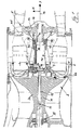
- Reference number 1 denotes a Slinger combustion chamber of a small gas turbine, which - as shown in particular in FIG. 1 - has a radial compressor 2 upstream.
- the so-called turbine part 5 of the small gas turbine or more precisely the turbine disk 5a of the turbine part 5 is connected to the compressor impeller 2a of this radial compressor 2 via a rotor shaft 4 running in the axial direction 3.
- the compressor impeller 2a, the rotor shaft 4 and the turbine disk 5a rotate about the so-called central axis 19 of the small gas turbine.
- the rotor shaft 4 is mounted by means of two roller bearings 35, 36 in the housing of the small gas turbine designated in its entirety with the reference number 37.
- a first roller bearing 35 is provided in the inflow region of the compressor impeller 2a and is therefore also referred to as a roller bearing 35 on the compressor part side, while the second roller bearing 36 provided upstream just before the turbine part 5 is also referred to as a turbine part side bearing 36.
- the radial compressor 2 promotes one to be fed to the combustion chamber 1 in the direction of the arrow 6 Airflow that is used within the combustion of the further the Combustion chamber 1 supplied fuel is required. Part of this simplicity for the sake of air flow also designated with the reference number 6 due to the differences in the different zones of the small gas turbine Pressure ratios, however, not into the combustion chamber 1, but instead on this or on its end wall facing the radial compressor 2 on the outside past in the so-called compressor back space 8. Furthermore, a small subset leak air from the combustion chamber also get into the compressor rear space 8. These two air flows mixing in the compressor rear space 8 are generally referred to as leakage air 6a.
- the compressor rear space 8 located on the rear side of the compressor impeller 2a must therefore be ventilated, i.e. the leakage air 6a must come from the compressor back space 8 can also be removed again.
- This is done at least in some areas, here, however, completely hollow rotor shaft 4, or more precisely about the interior 4a.
- the front of the compressor impeller 2a facing end of the rotor shaft 4 is flange-shaped and represents a so-called Crossing part 4b.
- this flange-like crossing part 4b here preferably three evenly distributed over the circumference of the intersection part 4b
- Vent holes 9 through which thus a connection between the rotor shaft interior 4a and ultimately the compressor rear space 8. in the the rest is via this flange-like crossing part 4b, the rotor shaft 4 with the compressor impeller 2a non-rotatably connected.
- the leakage air 6a is emitted via the crossing part 4b of the rotor shaft 4 discharged to the compressor rear space 8, but at the same time that in the combustion chamber 1 fuel to be burned supplied to the combustion chamber 1.
- the fuel is usually used one concentric to the axis of rotation of the radial compressor 2 or the rotor shaft 4 extending bore 11 in the compressor impeller 2a or more precisely through a provided therein Delivery pipe 12 ultimately directed to the combustion chamber 1.
- the fuel introduced in this way thus passes through the delivery pipe 12 and via a centrifugal siphon 14, which is explained in more detail below, into a preferred centrally in the intersection 4b of the rotor shaft 4, but away from the ventilation holes 9 provided distribution chamber 15, of which several in the radial direction Branch off 16 supply holes 17.
- supply holes 17 which are offset from the ventilation holes 9 are arranged so that the supply holes 17 and Do not cut vent holes 9, the fuel can therefore ultimately in reach the combustion chamber 1.
- Three such supply bores are preferred 17 evenly distributed over the circumference of the intersection part 4b.
- centrifugal siphon 14 which is provided between the delivery pipe 12 and the distributor chamber 15, for the sake of clarity, reference is made in particular to the enlarged illustration in FIG. 2 .
- the purpose of this centrifugal siphon 14 is to seal the initial area of the fuel injection system, namely the fuel injection tube 13 and the delivery pipe 12, from the combustion chamber 1, in particular in order to ensure excellent controllability of the entire fuel injection system of the small gas turbine, even at low speeds, and beyond Ensure the possibility of a windmill start often desired in small gas turbines as best as possible.
- the fuel brought in via the injection tube 13 comes out of the delivery pipe 12 again under the influence of centrifugal force onto the inner surface of a so-called distributor cone 20 and over this due to a baffle plate 21 provided in the intersection part 4b along the same via one between the free end of the distributor cone 20 and the baffle plate 21 provided first gap space 33 in the radial direction 16 outwards into the area of at least one, but in particular a plurality of axial grooves 22 made in the edge of the baffle plate 21.
- the fuel then passes through or through these grooves 22 along the Distribution cone 20 side facing away, ie along the side of the baffle plate 21 facing the combustion chamber 1 in the radial direction 16 viewed inward via a so-called second gap space 34, ie in the direction of the central axis 19 into the distribution chamber 15 already described.
- a screw connection designated by reference numeral 23 via which the compressor impeller 2a is flanged to the rotor shaft 4 or to the crossing part 4b thereof.
- the centrifugal siphon 14 or, more precisely, the one located within it Amount of fuel due to the rotation of the rotor shaft 4 acting centrifugal forces has / have the consequence that in the second gap 34 of the centrifugal siphon 14 a certain There is fuel pressure, i.e. in the second gap space 34 it is current in it fuel is compressed to a certain pressure value. This The fact is now used in such a way that one out of this second gap space 34 Branch of fuel branched off and ultimately the turbine bearing bearing 36 is supplied for lubrication and cooling purposes.
- a capillary tube 38 For this purpose branches off from the centrifugal siphon 14 on the combustion chamber side and thereby (with respect to the Fuel flow direction) upstream of the supply bores 17, i.e. from the second Gap space 34 of the centrifugal siphon 14, a capillary tube 38, via which one Part of the fuel quantity is supplied to the roller bearing 36 on the turbine part side.
- the term "Capillary tube” makes it clear that this is a fuel subset the element feeding the turbine part-side roller bearing 36 around a pipe or Tube or the like. In which there is a flow bore 38a with a relatively small flow cross-section.
- capillary tube 38 instead of a capillary tube (38) also another suitable element can be used that serves the same purpose, for example a hose with a relatively small flow cross-section.
- a correspondingly thin (flow) bore (38a) directly in the rotor shaft 4 be provided, via which a subset of fuel to the turbine part Rolling bearings 36 branched from the second gap 34 of the centrifugal siphon 14 fed becomes; also such (not shown here for the sake of simplicity) Embodiment should fall under the term of the capillary tube 38.
- capillary tube 38 is on the inlet side, i.e. suspended in the area of the centrifugal siphon 14, in the crossing part 4b of the rotor shaft 4 or in a suitably arranged receiving bore 39 in the crossing part 4b inserted.
- the capillary tube 38 then continues within the rotor shaft 4 and in sections in the interior 4a of the same, but in sections also in the wall of the rotor shaft (not denoted by a separate reference number) 4.
- the capillary tube 38 is suitable for this purpose in the rotor shaft wall inserted blind hole 40 inserted.
- the capillary tube opens 38 in the closed end of the blind hole 40, one of which is the wall of the Rotor shaft 4 branches off in the radial direction 16 penetrating bore 41, so that the capillary tube 38 under the influence of the centrifugal siphon 14th and starting from this introduced fuel subset through this hole 41 can get into a so-called bearing annulus 42, in which the turbine part Rolling bearing 36 is arranged.
- Said bearing annular space 42 is thus inward in the radial direction 16 the outside of the rotor shaft 4 and in the radial direction 16 to the outside by a not specified section of the housing 37 of the small gas turbine limited.
- the bearing annulus 42 (right side) by the turbine part side Rolling bearing 36 and viewed against the direction of flow (i.e. left side and thus towards the combustion chamber 1) by a labyrinth seal in particular Seal 43 limited.
- This seal 43 allows a slight passage of combustion chamber gas, i.e.
- the capillary tube 38 in the blind hole 40 is spaced slightly apart from the wall of the rotor shaft 4 over wide areas, so that the partial fuel quantity guided in the capillary tube 38 is as little as possible is heated by the hot rotor shaft 4.
- the use of an actual capillary tube 38 is considerably cheaper than if the fuel subset were supplied to the roller bearing 36 via a bore provided directly in the rotor shaft wall, since in the latter case the fuel subset would be heated until it evaporated, but can this and a large number of further details, in particular of a constructive nature, may be designed to deviate from the exemplary embodiment shown, without departing from the content of the claims.
Landscapes
- Engineering & Computer Science (AREA)
- Mechanical Engineering (AREA)
- General Engineering & Computer Science (AREA)
- Chemical & Material Sciences (AREA)
- Combustion & Propulsion (AREA)
- Structures Of Non-Positive Displacement Pumps (AREA)
- Turbine Rotor Nozzle Sealing (AREA)
Claims (4)
- Turbine à gaz miniature comportant une chambre de combustion radiale ou chambre à projection ainsi qu'un compresseur radial (2) en amont de la chambre de combustion radiale ou à projection (1) ou un compresseur diagonal ainsi qu'une partie de turbine (5) reliée à ce compresseur par un arbre de rotor (4) dirigé dans la direction axiale (3) et monté dans au moins un palier de roulement (36),
le combustible passant par un tube d'alimentation (12) prévu dans le rotor (2a) du compresseur radial/compresseur diagonal pour arriver dans une partie d'intersection (4b) de l'arbre (4) du rotor situé dans la zone de la chambre de combustion (1) proche du compresseur et être fourni à des perçages d'alimentation (17) de la chambre de combustion (1), ces perçages étant essentiellement dans la direction radiale (16),
et dans la partie d'intersection (4b) ou en amont de celle-ci un siphon centrifuge (14) en amont des perçages d'alimentation (17) est traversé par le combustible,
caractérisé en ce que
un tube capillaire (18) est issu du siphon centrifuge (14) du côté de la chambre de combustion et ainsi en amont des perçages d'alimentation (17), tube par lequel une fraction de combustible est fournie au palier de roulement (36) du côté de la turbine. - Turbine à gaz miniature selon la revendication 1,
dans laquelle le siphon centrifuge (14) est formé par une plaque brise-jet (21) à l'extrémité du tube d'alimentation (12) formant un premier intervalle (33) s'étendant vers l'extérieur dans la direction radiale (16), le combustible sortant du tube d'alimentation (12) passant par ce premier intervalle (33) pour arriver dans la zone d'au moins une rainure axiale (22) réalisée dans le bord de la plaque brise-jet (21) et par cette rainure dans un second intervalle (34) réalisé sur le côté de la plaque brise-jet (21) tourné vers la chambre de combustion (1) pour être dirigé de nouveau dans la direction radiale vers l'intérieur dans une chambre de distribution (15) d'où partent les perçages d'alimentation (7),
caractérisé en ce que
le tube capillaire (38) est issu du second intervalle (34) en amont de la chambre de distribution (15). - Turbine à gaz miniature selon la revendication 1 ou 2,
caractérisé en ce que
le tube capillaire (38) passe dans l'arbre (4) du rotor traversé par un perçage (41) avant la paroi, une fraction du combustible arrivant par ce perçage dans la chambre annulaire (42) logeant le palier de roulement (36). - Turbine à gaz miniature selon l'une des revendications précédentes,
caractérisé en ce que
la chambre annulaire de palier (42) est délimitée du côté de la chambre de combustion (1) par un joint (43) notamment réalisé comme joint en labyrinthe, permettant un passage réduit de gaz de la chambre de combustion.
Applications Claiming Priority (2)
| Application Number | Priority Date | Filing Date | Title |
|---|---|---|---|
| DE19852768A DE19852768A1 (de) | 1998-11-16 | 1998-11-16 | Kleingasturbine mit einer Radial- oder Slinger-Brennkammer |
| DE19852768 | 1998-11-16 |
Publications (3)
| Publication Number | Publication Date |
|---|---|
| EP1001223A2 EP1001223A2 (fr) | 2000-05-17 |
| EP1001223A3 EP1001223A3 (fr) | 2002-07-17 |
| EP1001223B1 true EP1001223B1 (fr) | 2003-07-23 |
Family
ID=7887943
Family Applications (1)
| Application Number | Title | Priority Date | Filing Date |
|---|---|---|---|
| EP99122467A Expired - Lifetime EP1001223B1 (fr) | 1998-11-16 | 1999-11-11 | Turbine à gaz avec injection du carburant rotatif |
Country Status (2)
| Country | Link |
|---|---|
| EP (1) | EP1001223B1 (fr) |
| DE (2) | DE19852768A1 (fr) |
Families Citing this family (3)
| Publication number | Priority date | Publication date | Assignee | Title |
|---|---|---|---|---|
| FR3045719B1 (fr) * | 2015-12-18 | 2020-09-18 | Snecma | Procede de lubrification et de refroidissement d'organes mecaniques d'une turbomachine par du carburant |
| FR3114866B1 (fr) * | 2020-10-01 | 2022-08-19 | Safran Helicopter Engines | Système d’injection de carburant dans une chambre de combustion centrifuge |
| US12065971B2 (en) * | 2022-09-30 | 2024-08-20 | Raytheon Technologies Corporation | Centrifugally pumped fuel system |
Family Cites Families (7)
| Publication number | Priority date | Publication date | Assignee | Title |
|---|---|---|---|---|
| DE1135244B (de) * | 1959-03-28 | 1962-08-23 | Bmw Triebwerkbau Ges M B H | Gasturbinenanlage, insbesondere Kleingasturbinenanlage |
| US4038815A (en) * | 1973-03-30 | 1977-08-02 | Northern Research And Engineering Corporation | Gas turbine |
| DE3637776A1 (de) * | 1986-11-06 | 1988-05-11 | Kloeckner Humboldt Deutz Ag | Schmiersystem fuer ein gasturbinentriebwerk |
| DE3714990A1 (de) * | 1987-05-06 | 1988-12-01 | Mtu Muenchen Gmbh | Propfan-turbotriebwerk |
| IT1219194B (it) * | 1988-04-11 | 1990-05-03 | Aris Spa | Turboreattore leggero modulare |
| US5526640A (en) * | 1994-05-16 | 1996-06-18 | Technical Directions, Inc. | Gas turbine engine including a bearing support tube cantilevered from a turbine nozzle wall |
| DE19846976A1 (de) | 1998-10-12 | 2000-04-13 | Bmw Rolls Royce Gmbh | Brennstoffeinspritzsystem für eine Radial- oder Slinger-Brennkammer einer Kleingasturbine |
-
1998
- 1998-11-16 DE DE19852768A patent/DE19852768A1/de not_active Withdrawn
-
1999
- 1999-11-11 DE DE59906345T patent/DE59906345D1/de not_active Expired - Lifetime
- 1999-11-11 EP EP99122467A patent/EP1001223B1/fr not_active Expired - Lifetime
Also Published As
| Publication number | Publication date |
|---|---|
| DE59906345D1 (de) | 2003-08-28 |
| EP1001223A3 (fr) | 2002-07-17 |
| DE19852768A1 (de) | 2000-05-18 |
| EP1001223A2 (fr) | 2000-05-17 |
Similar Documents
| Publication | Publication Date | Title |
|---|---|---|
| DE2325614C2 (de) | Notsystem zur Zuführung eines Schmiermittels | |
| EP1103706B1 (fr) | Chambre pour un palier d'une turbine à gaz | |
| DE2408839C2 (de) | Zweiwellen-Gasturbinentriebwerk | |
| DE69607718T2 (de) | Wälzlager mit dynamischer, ölversorgter Drainage | |
| EP2071131B1 (fr) | Etanchéification d'au moins un arbre à l'aide d'au moins un joint hydraulique | |
| DE69605014T2 (de) | Zentrifugalölabscheider für ein Schmierungsgehäuse | |
| EP2167792B1 (fr) | Turbocompresseur d'un véhicule présentant un dispositif d'étanchéité spécifique | |
| WO2009130124A1 (fr) | Système de palier avec un roulement double, turbocompresseur et procédé pour amener un agent lubrifiant jusqu’aux rangées de corps de roulement d’un roulement double | |
| DE2008209A1 (de) | Schmiersystem bei einem Turbinenmotor | |
| EP0718541A1 (fr) | Procédé et dispositif pour auto-lubrifier des palier d'une turbocompresseur | |
| DE3015650A1 (de) | Oelnebel-notschmiersystem fuer turbinenlager o.dgl. | |
| DE3007092A1 (de) | Schmiereinrichtung fuer waelzlager | |
| DE102007023380A1 (de) | Gasturbine | |
| EP3069051A1 (fr) | Cage de transmission planétaire avec alimentation en lubrifiant intégrée | |
| EP1327802B1 (fr) | Dispositif de joint hydraulique | |
| DE2733377A1 (de) | Schmiersystem fuer eine lageranordnung in einer turbine mit treibstoffzufuhr | |
| DE29724492U1 (de) | Vorrichtung zum Aufteilen einer mittels einer Gasströmung transportierten viskosen Flüssigkeit | |
| EP0123989B1 (fr) | Pompe centrifuge de lubrification pour turbocompresseur | |
| EP2995782A1 (fr) | Groupe motopropulseur dote d'une chambre de stockage et d'un dispositif de conduite d'huile | |
| DE102013213520A1 (de) | Vorrichtung und Verfahren zum Ableiten von Sperrluft in einem Turbofan-Triebwerk | |
| DE1751639B2 (de) | Dichtungsanordnung für ein Gasturbinentriebwerk mit Hohl- und Innenwelle | |
| EP1001223B1 (fr) | Turbine à gaz avec injection du carburant rotatif | |
| DE3201008A1 (de) | Duese mit doppelfunktion fuer notoel/nebel-system | |
| EP1121561B1 (fr) | Systeme d'injection de carburant pour une chambre de combustion radiale d'une petite turbine a gaz | |
| DE102016124283A1 (de) | Hydrodynamische Kupplung |
Legal Events
| Date | Code | Title | Description |
|---|---|---|---|
| PUAI | Public reference made under article 153(3) epc to a published international application that has entered the european phase |
Free format text: ORIGINAL CODE: 0009012 |
|
| AK | Designated contracting states |
Kind code of ref document: A2 Designated state(s): AT BE CH CY DE DK ES FI FR GB GR IE IT LI LU MC NL PT SE |
|
| AX | Request for extension of the european patent |
Free format text: AL;LT;LV;MK;RO;SI |
|
| 17P | Request for examination filed |
Effective date: 20000427 |
|
| RAP1 | Party data changed (applicant data changed or rights of an application transferred) |
Owner name: ROLLS-ROYCE DEUTSCHLAND LTD & CO KG |
|
| PUAL | Search report despatched |
Free format text: ORIGINAL CODE: 0009013 |
|
| AK | Designated contracting states |
Kind code of ref document: A3 Designated state(s): AT BE CH CY DE DK ES FI FR GB GR IE IT LI LU MC NL PT SE |
|
| AX | Request for extension of the european patent |
Free format text: AL;LT;LV;MK;RO;SI |
|
| RIC1 | Information provided on ipc code assigned before grant |
Free format text: 7F 23R 3/38 A, 7F 01D 25/18 B, 7F 01M 9/04 B |
|
| GRAH | Despatch of communication of intention to grant a patent |
Free format text: ORIGINAL CODE: EPIDOS IGRA |
|
| AKX | Designation fees paid |
Designated state(s): DE FR GB IT |
|
| RIN1 | Information on inventor provided before grant (corrected) |
Inventor name: BOECK, ALEXANDER |
|
| GRAH | Despatch of communication of intention to grant a patent |
Free format text: ORIGINAL CODE: EPIDOS IGRA |
|
| GRAA | (expected) grant |
Free format text: ORIGINAL CODE: 0009210 |
|
| RIN1 | Information on inventor provided before grant (corrected) |
Inventor name: BOECK, ALEXANDER |
|
| AK | Designated contracting states |
Designated state(s): DE FR GB IT |
|
| PG25 | Lapsed in a contracting state [announced via postgrant information from national office to epo] |
Ref country code: IT Free format text: LAPSE BECAUSE OF FAILURE TO SUBMIT A TRANSLATION OF THE DESCRIPTION OR TO PAY THE FEE WITHIN THE PRESCRIBED TIME-LIMIT;WARNING: LAPSES OF ITALIAN PATENTS WITH EFFECTIVE DATE BEFORE 2007 MAY HAVE OCCURRED AT ANY TIME BEFORE 2007. THE CORRECT EFFECTIVE DATE MAY BE DIFFERENT FROM THE ONE RECORDED. Effective date: 20030723 Ref country code: GB Free format text: LAPSE BECAUSE OF FAILURE TO SUBMIT A TRANSLATION OF THE DESCRIPTION OR TO PAY THE FEE WITHIN THE PRESCRIBED TIME-LIMIT Effective date: 20030723 |
|
| REG | Reference to a national code |
Ref country code: GB Ref legal event code: FG4D Free format text: NOT ENGLISH |
|
| REG | Reference to a national code |
Ref country code: IE Ref legal event code: FG4D Free format text: GERMAN |
|
| REF | Corresponds to: |
Ref document number: 59906345 Country of ref document: DE Date of ref document: 20030828 Kind code of ref document: P |
|
| GBV | Gb: ep patent (uk) treated as always having been void in accordance with gb section 77(7)/1977 [no translation filed] |
Effective date: 20030723 |
|
| GBT | Gb: translation of ep patent filed (gb section 77(6)(a)/1977) |
Effective date: 20040102 |
|
| REG | Reference to a national code |
Ref country code: IE Ref legal event code: FD4D |
|
| ET | Fr: translation filed | ||
| PLBE | No opposition filed within time limit |
Free format text: ORIGINAL CODE: 0009261 |
|
| STAA | Information on the status of an ep patent application or granted ep patent |
Free format text: STATUS: NO OPPOSITION FILED WITHIN TIME LIMIT |
|
| 26N | No opposition filed |
Effective date: 20040426 |
|
| PGFP | Annual fee paid to national office [announced via postgrant information from national office to epo] |
Ref country code: DE Payment date: 20091127 Year of fee payment: 11 |
|
| PGFP | Annual fee paid to national office [announced via postgrant information from national office to epo] |
Ref country code: GB Payment date: 20091125 Year of fee payment: 11 Ref country code: FR Payment date: 20091201 Year of fee payment: 11 |
|
| GBPC | Gb: european patent ceased through non-payment of renewal fee |
Effective date: 20101111 |
|
| REG | Reference to a national code |
Ref country code: FR Ref legal event code: ST Effective date: 20110801 |
|
| REG | Reference to a national code |
Ref country code: DE Ref legal event code: R119 Ref document number: 59906345 Country of ref document: DE Effective date: 20110601 Ref country code: DE Ref legal event code: R119 Ref document number: 59906345 Country of ref document: DE Effective date: 20110531 |
|
| PG25 | Lapsed in a contracting state [announced via postgrant information from national office to epo] |
Ref country code: DE Free format text: LAPSE BECAUSE OF NON-PAYMENT OF DUE FEES Effective date: 20110531 |
|
| PG25 | Lapsed in a contracting state [announced via postgrant information from national office to epo] |
Ref country code: FR Free format text: LAPSE BECAUSE OF NON-PAYMENT OF DUE FEES Effective date: 20101130 |
|
| PG25 | Lapsed in a contracting state [announced via postgrant information from national office to epo] |
Ref country code: GB Free format text: LAPSE BECAUSE OF FAILURE TO SUBMIT A TRANSLATION OF THE DESCRIPTION OR TO PAY THE FEE WITHIN THE PRESCRIBED TIME-LIMIT Effective date: 20101111 |