EP1001225B1 - Steuereinrichtung für Sicherheitsventil an Mehrzweckkochmulden - Google Patents
Steuereinrichtung für Sicherheitsventil an Mehrzweckkochmulden Download PDFInfo
- Publication number
- EP1001225B1 EP1001225B1 EP99122471A EP99122471A EP1001225B1 EP 1001225 B1 EP1001225 B1 EP 1001225B1 EP 99122471 A EP99122471 A EP 99122471A EP 99122471 A EP99122471 A EP 99122471A EP 1001225 B1 EP1001225 B1 EP 1001225B1
- Authority
- EP
- European Patent Office
- Prior art keywords
- rod
- tap
- shaft
- cooking surface
- slide
- Prior art date
- Legal status (The legal status is an assumption and is not a legal conclusion. Google has not performed a legal analysis and makes no representation as to the accuracy of the status listed.)
- Expired - Lifetime
Links
Images

Classifications
-
- F—MECHANICAL ENGINEERING; LIGHTING; HEATING; WEAPONS; BLASTING
- F24—HEATING; RANGES; VENTILATING
- F24C—DOMESTIC STOVES OR RANGES ; DETAILS OF DOMESTIC STOVES OR RANGES, OF GENERAL APPLICATION
- F24C3/00—Stoves or ranges for gaseous fuels
- F24C3/12—Arrangement or mounting of control or safety devices
- F24C3/126—Arrangement or mounting of control or safety devices on ranges
Definitions
- the invention consists of a device which enables control of the tap of a burner, equipped with a safety valve, belonging to a built-in multi-purpose gas cooking surface.
- the shaft of the knob which controls the tap that regulates gas flow to one of the burners of the cooking surface is connected to the shaft of the tap by a variable-length rod comprising adjustable means which enable the minimum length of the rod to be set, the rod thus being able to transmit to the shaft of the tap the axial force required to disable a safety valve built into the bumer.
- Multi-purpose built-in cooking surfaces and ovens are known and available on the market, which, when installed in association with one another, make up an assembly in which also the controls of the burners of the cooking surface are located on the front of the oven.
- This arrangement is advantageous for the user in that it makes it possible to increase the space available for arranging the burners and grills, but involves the problem of connecting mechanically each knob located on the front of the oven with the tap that regulates gas flow to the corresponding bumer.
- the said tap is located in the bottom part of the cooking surface at a distance from the corresponding knob which is different for each tap and depends upon a number of factors, such as, for example, the position of the cooking surface with respect to the kitchen working surface, the thickness of the kitchen working surface, the height at which the oven is installed, etc.
- variable-length rod comprising two or more parts which are free to slide with respect to one another
- particular universal joints one of which is fixed to the tap shaft, and the other to the knob shaft.
- variable-length rod Normally one end of the variable-length rod is fixed to the tap shaft before the cooking surface is inserted into the cabinet, whilst the other end of the variable-length rod (preferably, but not necessarily, completely extended to enable easier access to the rear part of the oven front) is fixed to the knob shaft before the oven front is inserted into the cabinet.
- each variable-length rod When the front of the oven is inserted into the cabinet, the mutual sliding of the parts that make up each variable-length rod automatically adjusts the length of the rod to the distance existing between the shaft of the knob and the shaft of the tap to which it is fixed.
- Each variable-length rod is designed to transmit to the tap shaft a rotation exerted by the user on the knob to regulate the intensity of the flame, but is not able to transmit to the tap shaft an axial force.
- EP A 412 041 discloses a control mechanism for connecting a control button to a cook comprising a double articulation and an axis comprising two elements able to reciprocally slide. Said axis can transmit rotation, but not a longitudinal movement.
- GB 827,650 discloses a control device wherein two shafts, for transmitting rotation from a knob to a control mechanism of an oven, are free to slide reciprocally. The device does not allow any other movement than rotation.
- the shaft of a knob is connected to the shaft of the tap by means of a variable-length rod which is not able to transmit to the tap shaft the pressure exerted by the user on the knob. It is not therefore possible to equip a multipurpose cooking surface with burners each comprising a safety valve.
- the control device which is the subject of the present invention makes it possible to overcome the serious problems referred to above in that it is able to transmit to the shaft of the tap not only a rotation exerted by the user on the knob to regulate the intensity of the flame, but also a pressure exerted by the user on the knob.
- the subject of the present invention is a device for controlling a tap equipped with a safety valve belonging to a multipurpose gas cooking surface, the said tap comprising a variable-length rod consisting of a first rod telescopically inserted into a second rod in which it is free to slide.
- the free ends of the first rod and of the second rod carry fastening means (comprising a universal joint) for coupling them mechanically to the shaft of the control knob and to the tap shaft, respectively.
- the device further comprises a friction slide inserted on the first rod, said friction slide further comprising means designed to fix it in a reversible way to the first rod and a leaf spring inserted between one inner wall of the slide and the adjacent outer wall of the first rod.
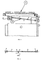
- FIG 1 is a schematic representation of an assembly comprising a multipurpose oven 5 and a multipurpose cooking surface 1, built into the same cabinet, in which the knob 4 located on the front of the oven 5 is connected to the tap 2 of one of the burners of the cooking surface 1 by the control device 3 (which will be better described in the exploded view of Figure 3), which comprises a variable-length rod consisting of one first rod 31 telescopically inserted into one second rod 32, inside which it is free to slide.
- the free ends of the two rods (31, 32) are mechanically coupled to the shaft of the knob 4 and to the shaft of the tap 2, respectively.
- blocking means 33 (consisting, in the preferred embodiment described herein, of a friction slide, which will be better described with reference to Figure 3) which can be adjusted to set the minimum length of the variable-length rod.
- FIG 2 is an enlarged partial schematic view of the assembly of Figure 1 and has the purpose of better illustrating the knob 4 connected to the tap 2 of the burner of the control device 3 consisting of the first rod 31 telescopically inserted into the second rod 32 (in which it is free to slide) and of the friction slide, inserted on the first rod 31, which constitutes the blocking means 33.
- the free ends of the two rods (31, 32) are mechanically coupled to the shaft of the knob 4 and to the shaft of the tap 2, respectively.
- Figure 3 is an exploded view of a control device 3 made according to the invention.
- the first rod 31, the second rod 32, the friction slide that constitutes the blocking means 33, and the fixing means 34 located at the free ends of the two rods (31, 32) and designed to couple them mechanically to the shaft of the knob 4 and to the shaft of the tap 2, respectively.
- the friction means of the slide consist of a leaf spring 35 inserted between one inside wall of the slide and the adjacent outer wall of the first rod 31.
- the leaf spring 35 it is possible to replace the leaf spring 35 with another, functionally equivalent, elastic element, not described herein in that it is in itself known.
- the leaf spring 35 may be seen both by itself and inserted into the friction slide.
- the friction slide moreover comprises fixing means 36 (consisting, in the example of embodiment illustrated herein, of a screw inserted into a threaded hole made in one wall of the friction slide) that are designed to fix the slide in a reversible way to the first rod 31.
- each variable-length rod is fixed (by means of the fixing means 34) to the shaft of the tap 2 of one of the burners of the cooking surface 1; each variable-length rod is extended, and the other end of the rod is fixed (using the fixing means 34) to the shaft of the, corresponding knob 4 located on the front of the oven 5 before the oven 5 is inserted into the cabinet.
- the oven 5 is set into the cabinet but not fastened in its housing.
- Each variable-length rod automatically adapts its length to the distance between the shaft of the knob 4 and the shaft of the tap 2 to which each one is fixed.
- the mutual displacement of the second rod 32 with respect to the first rod 31 causes the slide to run along the first rod 31. Since the slide is a friction slide, it remains in the position that it reaches when the oven 5 is completely inserted into the cabinet, even when the oven 5 is taken out again.
- the oven 5 is inserted into the cabinet and fastened in its housing.
- the second rod 32 comes to bear upon the slide which is fixed to the first rod 31, thus limiting the minimum length of the variable-length rod to the effective distance between the shaft of the knob 4 and the shaft of the tap 2.
- the rod is able to transmit to the shaft of the tap 2 also the axial force exerted by the user on the knob 4 to disable the safety valve when he lights the bumer.
Landscapes
- Engineering & Computer Science (AREA)
- Chemical & Material Sciences (AREA)
- Combustion & Propulsion (AREA)
- Mechanical Engineering (AREA)
- General Engineering & Computer Science (AREA)
- Feeding And Controlling Fuel (AREA)
- Fluid-Pressure Circuits (AREA)
Claims (2)
- Steuereinrichtung für einen mit einem Sicherheitsventil ausgestatteten Hahn (2), welcher zu einer mit Gas betriebenen Mehrzweckkochmulde (1) gehört, wobei der genannte Hahn (2) einen längenveränderlichen Stab umfasst, welcher einen ersten Stab (31) enthält, der in einen zweiten Stab (32) gesteckt ist, in welchem er frei gleiten kann, wobei die freien Enden des ersten Stabes (31) und des zweiten Stabes (32) mechanisch an die Welle des Bedienknopfes (4) bzw. an die Welle des Hahnes (2) über Befestigungsmittel, welche eine Universalverbindung umfassen, gekoppelt werden können, dadurch gekennzeichnet, dass sie ein auf den ersten Stab (31) aufgesetztes Gleitelement umfasst, wobei das genannte Gleitelement außerdem Mittel (36) umfasst, die so ausgelegt sind, dass sie es auf umkehrbare Weise am erstem Stab (31) befestigen, sowie eine Blattfeder (35), die zwischen eine Innenwand des Schiebers und die angrenzende Außenwand des ersten Stabes (31) eingesetzt ist.
- Steuereinrichtung gemäß Anspruch 1, dadurch gekennzeichnet, dass die umkehrbaren Befestigungsmittel (36) aus einer Schraube bestehen, welche in ein mit Gewinde versehenes Loch geschraubt ist, welches in einer Wand des reibschlüssigen Gleitelements angelegt ist.
Applications Claiming Priority (2)
| Application Number | Priority Date | Filing Date | Title |
|---|---|---|---|
| IT1998MI002466A IT1303752B1 (it) | 1998-11-13 | 1998-11-13 | Dispositivo di comando di un rubinetto dotato di valvola disicurezza appartenente ad un piano di cottura a gas polivalente. |
| ITMI982466 | 1998-11-13 |
Publications (2)
| Publication Number | Publication Date |
|---|---|
| EP1001225A1 EP1001225A1 (de) | 2000-05-17 |
| EP1001225B1 true EP1001225B1 (de) | 2004-02-11 |
Family
ID=11381055
Family Applications (1)
| Application Number | Title | Priority Date | Filing Date |
|---|---|---|---|
| EP99122471A Expired - Lifetime EP1001225B1 (de) | 1998-11-13 | 1999-11-11 | Steuereinrichtung für Sicherheitsventil an Mehrzweckkochmulden |
Country Status (5)
| Country | Link |
|---|---|
| EP (1) | EP1001225B1 (de) |
| AT (1) | ATE259491T1 (de) |
| DE (1) | DE69914702D1 (de) |
| ES (1) | ES2216415T3 (de) |
| IT (1) | IT1303752B1 (de) |
Families Citing this family (5)
| Publication number | Priority date | Publication date | Assignee | Title |
|---|---|---|---|---|
| ES2208006B1 (es) * | 2001-04-05 | 2005-11-01 | Bsh Electrodomesticos España, S.A. | Barra telescopica para aparatos electrodomesticos. |
| ITMI20011531A1 (it) * | 2001-07-18 | 2003-01-18 | Miglio Emilio S N C | Dispositivo per il comando di rubinetti per piani di cottura |
| DE10159253A1 (de) * | 2001-12-03 | 2003-06-18 | Bsh Bosch Siemens Hausgeraete | Gaskochstelle |
| ES1064333Y (es) | 2006-11-24 | 2007-06-01 | Coprecitec Sl | "aparato de coccion a gas con un panel de control oculto" |
| CN112556134A (zh) * | 2020-12-29 | 2021-03-26 | 苏州巨坦达科技有限公司 | 一种基于中央空调智慧能源节能管控设备 |
Family Cites Families (3)
| Publication number | Priority date | Publication date | Assignee | Title |
|---|---|---|---|---|
| GB827650A (en) * | 1955-03-19 | 1960-02-10 | Simplex Electric Co Ltd | Improvements relating to drives for control devices of cooking stoves |
| NL166117C (nl) * | 1978-08-31 | 1981-06-15 | Atag Bv Apparatenfab | Kooktoestel. |
| ES2016707A6 (es) * | 1989-07-25 | 1990-11-16 | Corbero Sa | Mecanismo auto-ajustable de mando para aparatos domesticos. |
-
1998
- 1998-11-13 IT IT1998MI002466A patent/IT1303752B1/it active
-
1999
- 1999-11-11 ES ES99122471T patent/ES2216415T3/es not_active Expired - Lifetime
- 1999-11-11 EP EP99122471A patent/EP1001225B1/de not_active Expired - Lifetime
- 1999-11-11 DE DE69914702T patent/DE69914702D1/de not_active Expired - Lifetime
- 1999-11-11 AT AT99122471T patent/ATE259491T1/de not_active IP Right Cessation
Also Published As
| Publication number | Publication date |
|---|---|
| IT1303752B1 (it) | 2001-02-23 |
| ITMI982466A1 (it) | 2000-05-13 |
| EP1001225A1 (de) | 2000-05-17 |
| ATE259491T1 (de) | 2004-02-15 |
| ES2216415T3 (es) | 2004-10-16 |
| DE69914702D1 (de) | 2004-03-18 |
Similar Documents
| Publication | Publication Date | Title |
|---|---|---|
| US11262078B2 (en) | Knob assembly with display device and cooking apparatus having knob assembly | |
| US6375150B1 (en) | Knob for gas apparatus with safety button | |
| EP1001225A1 (de) | Steuereinrichtung für Sicherheitsventil an Mehrzweckkochmulden | |
| EP0412041A2 (de) | Selbstregulierende Steuermechanismus für Haushaltsgeräte | |
| GB2225826A (en) | Rotary control assembly for appliances | |
| US6966582B1 (en) | Lock rod clutch for oven latch | |
| EP3364108B1 (de) | Knopfanordnung und kochgerät mit einer knopfanordnung | |
| US6000390A (en) | Control mechanism with gas safety valve for a gas range | |
| US6553986B1 (en) | Burner for a gas barbecue grill | |
| EP0623787A1 (de) | Herd | |
| EP2827060A1 (de) | Nockengashahn mit Kücken und integriertem Nocken für Haushalts-Kochgeräte | |
| CN1757972B (zh) | 炉具用操作钮 | |
| KR100691058B1 (ko) | 가스 풍로 | |
| CN216481113U (zh) | 炉头结构及灶具 | |
| GB2177790A (en) | Cookers and hobs | |
| US2488330A (en) | Safety shutoff device for carbonaceous fuel burners | |
| US2079504A (en) | Gas range | |
| EP0725250B1 (de) | Steuer- und Sicherheitsvorrichtung für Gasgeräte | |
| GB2059550A (en) | Cooker Control Means | |
| EP0558462B1 (de) | Steuerhebel für Hähne an Kochmulden und an Gaskochern | |
| KR102342951B1 (ko) | 유니버설 조인트와 이를 구비하는 노브 조립체 및 가전기기 | |
| KR102206982B1 (ko) | 유니버설 조인트와 이를 구비하는 노브 조립체 및 가전기기 | |
| IT8224607A1 (it) | Cucina a gas di qualsiasi genere | |
| CN211041054U (zh) | 气动式控制电磁炉火候大小的火候控制装置 | |
| ES2208006B1 (es) | Barra telescopica para aparatos electrodomesticos. |
Legal Events
| Date | Code | Title | Description |
|---|---|---|---|
| PUAI | Public reference made under article 153(3) epc to a published international application that has entered the european phase |
Free format text: ORIGINAL CODE: 0009012 |
|
| AK | Designated contracting states |
Kind code of ref document: A1 Designated state(s): AT BE CH CY DE DK ES FI FR GB GR IE IT LI LU MC NL PT SE |
|
| AX | Request for extension of the european patent |
Free format text: AL;LT;LV;MK;RO;SI |
|
| 17P | Request for examination filed |
Effective date: 20001106 |
|
| AKX | Designation fees paid |
Free format text: AT BE CH CY DE DK ES FI FR GB GR IE IT LI LU MC NL PT SE |
|
| AXX | Extension fees paid |
Free format text: SI PAYMENT 20001106 |
|
| 17Q | First examination report despatched |
Effective date: 20020531 |
|
| GRAP | Despatch of communication of intention to grant a patent |
Free format text: ORIGINAL CODE: EPIDOSNIGR1 |
|
| GRAS | Grant fee paid |
Free format text: ORIGINAL CODE: EPIDOSNIGR3 |
|
| GRAA | (expected) grant |
Free format text: ORIGINAL CODE: 0009210 |
|
| GRAL | Information related to payment of fee for publishing/printing deleted |
Free format text: ORIGINAL CODE: EPIDOSDIGR3 |
|
| GRAS | Grant fee paid |
Free format text: ORIGINAL CODE: EPIDOSNIGR3 |
|
| AK | Designated contracting states |
Kind code of ref document: B1 Designated state(s): AT BE CH CY DE DK ES FI FR GB GR IE IT LI LU MC NL PT SE |
|
| AX | Request for extension of the european patent |
Extension state: SI |
|
| PG25 | Lapsed in a contracting state [announced via postgrant information from national office to epo] |
Ref country code: NL Free format text: LAPSE BECAUSE OF FAILURE TO SUBMIT A TRANSLATION OF THE DESCRIPTION OR TO PAY THE FEE WITHIN THE PRESCRIBED TIME-LIMIT Effective date: 20040211 Ref country code: LI Free format text: LAPSE BECAUSE OF FAILURE TO SUBMIT A TRANSLATION OF THE DESCRIPTION OR TO PAY THE FEE WITHIN THE PRESCRIBED TIME-LIMIT Effective date: 20040211 Ref country code: IT Free format text: LAPSE BECAUSE OF FAILURE TO SUBMIT A TRANSLATION OF THE DESCRIPTION OR TO PAY THE FEE WITHIN THE PRESCRIBED TIME-LIMIT;WARNING: LAPSES OF ITALIAN PATENTS WITH EFFECTIVE DATE BEFORE 2007 MAY HAVE OCCURRED AT ANY TIME BEFORE 2007. THE CORRECT EFFECTIVE DATE MAY BE DIFFERENT FROM THE ONE RECORDED. Effective date: 20040211 Ref country code: FR Free format text: LAPSE BECAUSE OF FAILURE TO SUBMIT A TRANSLATION OF THE DESCRIPTION OR TO PAY THE FEE WITHIN THE PRESCRIBED TIME-LIMIT Effective date: 20040211 Ref country code: FI Free format text: LAPSE BECAUSE OF FAILURE TO SUBMIT A TRANSLATION OF THE DESCRIPTION OR TO PAY THE FEE WITHIN THE PRESCRIBED TIME-LIMIT Effective date: 20040211 Ref country code: CY Free format text: LAPSE BECAUSE OF FAILURE TO SUBMIT A TRANSLATION OF THE DESCRIPTION OR TO PAY THE FEE WITHIN THE PRESCRIBED TIME-LIMIT Effective date: 20040211 Ref country code: CH Free format text: LAPSE BECAUSE OF FAILURE TO SUBMIT A TRANSLATION OF THE DESCRIPTION OR TO PAY THE FEE WITHIN THE PRESCRIBED TIME-LIMIT Effective date: 20040211 Ref country code: BE Free format text: LAPSE BECAUSE OF FAILURE TO SUBMIT A TRANSLATION OF THE DESCRIPTION OR TO PAY THE FEE WITHIN THE PRESCRIBED TIME-LIMIT Effective date: 20040211 Ref country code: AT Free format text: LAPSE BECAUSE OF FAILURE TO SUBMIT A TRANSLATION OF THE DESCRIPTION OR TO PAY THE FEE WITHIN THE PRESCRIBED TIME-LIMIT Effective date: 20040211 |
|
| REG | Reference to a national code |
Ref country code: GB Ref legal event code: FG4D |
|
| REG | Reference to a national code |
Ref country code: CH Ref legal event code: EP |
|
| REG | Reference to a national code |
Ref country code: IE Ref legal event code: FG4D |
|
| REF | Corresponds to: |
Ref document number: 69914702 Country of ref document: DE Date of ref document: 20040318 Kind code of ref document: P |
|
| PG25 | Lapsed in a contracting state [announced via postgrant information from national office to epo] |
Ref country code: SE Free format text: LAPSE BECAUSE OF FAILURE TO SUBMIT A TRANSLATION OF THE DESCRIPTION OR TO PAY THE FEE WITHIN THE PRESCRIBED TIME-LIMIT Effective date: 20040511 Ref country code: GR Free format text: LAPSE BECAUSE OF FAILURE TO SUBMIT A TRANSLATION OF THE DESCRIPTION OR TO PAY THE FEE WITHIN THE PRESCRIBED TIME-LIMIT Effective date: 20040511 Ref country code: DK Free format text: LAPSE BECAUSE OF FAILURE TO SUBMIT A TRANSLATION OF THE DESCRIPTION OR TO PAY THE FEE WITHIN THE PRESCRIBED TIME-LIMIT Effective date: 20040511 |
|
| PG25 | Lapsed in a contracting state [announced via postgrant information from national office to epo] |
Ref country code: DE Free format text: LAPSE BECAUSE OF FAILURE TO SUBMIT A TRANSLATION OF THE DESCRIPTION OR TO PAY THE FEE WITHIN THE PRESCRIBED TIME-LIMIT Effective date: 20040512 |
|
| NLV1 | Nl: lapsed or annulled due to failure to fulfill the requirements of art. 29p and 29m of the patents act | ||
| REG | Reference to a national code |
Ref country code: CH Ref legal event code: PL |
|
| REG | Reference to a national code |
Ref country code: ES Ref legal event code: FG2A Ref document number: 2216415 Country of ref document: ES Kind code of ref document: T3 |
|
| PG25 | Lapsed in a contracting state [announced via postgrant information from national office to epo] |
Ref country code: LU Free format text: LAPSE BECAUSE OF NON-PAYMENT OF DUE FEES Effective date: 20041111 Ref country code: IE Free format text: LAPSE BECAUSE OF NON-PAYMENT OF DUE FEES Effective date: 20041111 |
|
| PG25 | Lapsed in a contracting state [announced via postgrant information from national office to epo] |
Ref country code: MC Free format text: LAPSE BECAUSE OF NON-PAYMENT OF DUE FEES Effective date: 20041130 |
|
| PLBE | No opposition filed within time limit |
Free format text: ORIGINAL CODE: 0009261 |
|
| STAA | Information on the status of an ep patent application or granted ep patent |
Free format text: STATUS: NO OPPOSITION FILED WITHIN TIME LIMIT |
|
| PGFP | Annual fee paid to national office [announced via postgrant information from national office to epo] |
Ref country code: GB Payment date: 20050111 Year of fee payment: 6 |
|
| EN | Fr: translation not filed | ||
| 26N | No opposition filed |
Effective date: 20041112 |
|
| REG | Reference to a national code |
Ref country code: IE Ref legal event code: MM4A |
|
| PG25 | Lapsed in a contracting state [announced via postgrant information from national office to epo] |
Ref country code: GB Free format text: LAPSE BECAUSE OF NON-PAYMENT OF DUE FEES Effective date: 20051111 |
|
| GBPC | Gb: european patent ceased through non-payment of renewal fee |
Effective date: 20051111 |
|
| PG25 | Lapsed in a contracting state [announced via postgrant information from national office to epo] |
Ref country code: PT Free format text: LAPSE BECAUSE OF NON-PAYMENT OF DUE FEES Effective date: 20040711 |
|
| PGFP | Annual fee paid to national office [announced via postgrant information from national office to epo] |
Ref country code: ES Payment date: 20101120 Year of fee payment: 12 |
|
| REG | Reference to a national code |
Ref country code: ES Ref legal event code: FD2A Effective date: 20131029 |
|
| PG25 | Lapsed in a contracting state [announced via postgrant information from national office to epo] |
Ref country code: ES Free format text: LAPSE BECAUSE OF NON-PAYMENT OF DUE FEES Effective date: 20111112 |