EP1001229A2 - Elément d'expansion et unité de soupape à utiliser avec cet élément - Google Patents
Elément d'expansion et unité de soupape à utiliser avec cet élément Download PDFInfo
- Publication number
- EP1001229A2 EP1001229A2 EP99122508A EP99122508A EP1001229A2 EP 1001229 A2 EP1001229 A2 EP 1001229A2 EP 99122508 A EP99122508 A EP 99122508A EP 99122508 A EP99122508 A EP 99122508A EP 1001229 A2 EP1001229 A2 EP 1001229A2
- Authority
- EP
- European Patent Office
- Prior art keywords
- valve
- pressure
- refrigerant
- control valve
- pressure side
- Prior art date
- Legal status (The legal status is an assumption and is not a legal conclusion. Google has not performed a legal analysis and makes no representation as to the accuracy of the status listed.)
- Withdrawn
Links
Images

Classifications
-
- B—PERFORMING OPERATIONS; TRANSPORTING
- B60—VEHICLES IN GENERAL
- B60H—ARRANGEMENTS OF HEATING, COOLING, VENTILATING OR OTHER AIR-TREATING DEVICES SPECIALLY ADAPTED FOR PASSENGER OR GOODS SPACES OF VEHICLES
- B60H1/00—Heating, cooling or ventilating devices
- B60H1/00271—HVAC devices specially adapted for particular vehicle parts or components and being connected to the vehicle HVAC unit
-
- F—MECHANICAL ENGINEERING; LIGHTING; HEATING; WEAPONS; BLASTING
- F25—REFRIGERATION OR COOLING; COMBINED HEATING AND REFRIGERATION SYSTEMS; HEAT PUMP SYSTEMS; MANUFACTURE OR STORAGE OF ICE; LIQUEFACTION SOLIDIFICATION OF GASES
- F25B—REFRIGERATION MACHINES, PLANTS OR SYSTEMS; COMBINED HEATING AND REFRIGERATION SYSTEMS; HEAT PUMP SYSTEMS
- F25B41/00—Fluid-circulation arrangements
- F25B41/30—Expansion means; Dispositions thereof
- F25B41/31—Expansion valves
- F25B41/32—Expansion valves having flow rate limiting means other than the valve member, e.g. having bypass orifices in the valve body
-
- F—MECHANICAL ENGINEERING; LIGHTING; HEATING; WEAPONS; BLASTING
- F25—REFRIGERATION OR COOLING; COMBINED HEATING AND REFRIGERATION SYSTEMS; HEAT PUMP SYSTEMS; MANUFACTURE OR STORAGE OF ICE; LIQUEFACTION SOLIDIFICATION OF GASES
- F25B—REFRIGERATION MACHINES, PLANTS OR SYSTEMS; COMBINED HEATING AND REFRIGERATION SYSTEMS; HEAT PUMP SYSTEMS
- F25B41/00—Fluid-circulation arrangements
- F25B41/30—Expansion means; Dispositions thereof
- F25B41/31—Expansion valves
- F25B41/325—Expansion valves having two or more valve members
-
- F—MECHANICAL ENGINEERING; LIGHTING; HEATING; WEAPONS; BLASTING
- F25—REFRIGERATION OR COOLING; COMBINED HEATING AND REFRIGERATION SYSTEMS; HEAT PUMP SYSTEMS; MANUFACTURE OR STORAGE OF ICE; LIQUEFACTION SOLIDIFICATION OF GASES
- F25B—REFRIGERATION MACHINES, PLANTS OR SYSTEMS; COMBINED HEATING AND REFRIGERATION SYSTEMS; HEAT PUMP SYSTEMS
- F25B41/00—Fluid-circulation arrangements
- F25B41/30—Expansion means; Dispositions thereof
- F25B41/31—Expansion valves
- F25B41/33—Expansion valves with the valve member being actuated by the fluid pressure, e.g. by the pressure of the refrigerant
- F25B41/335—Expansion valves with the valve member being actuated by the fluid pressure, e.g. by the pressure of the refrigerant via diaphragms
-
- F—MECHANICAL ENGINEERING; LIGHTING; HEATING; WEAPONS; BLASTING
- F25—REFRIGERATION OR COOLING; COMBINED HEATING AND REFRIGERATION SYSTEMS; HEAT PUMP SYSTEMS; MANUFACTURE OR STORAGE OF ICE; LIQUEFACTION SOLIDIFICATION OF GASES
- F25B—REFRIGERATION MACHINES, PLANTS OR SYSTEMS; COMBINED HEATING AND REFRIGERATION SYSTEMS; HEAT PUMP SYSTEMS
- F25B9/00—Compression machines, plants or systems, in which the refrigerant is air or other gas of low boiling point
- F25B9/002—Compression machines, plants or systems, in which the refrigerant is air or other gas of low boiling point characterised by the refrigerant
- F25B9/008—Compression machines, plants or systems, in which the refrigerant is air or other gas of low boiling point characterised by the refrigerant the refrigerant being carbon dioxide
-
- F—MECHANICAL ENGINEERING; LIGHTING; HEATING; WEAPONS; BLASTING
- F25—REFRIGERATION OR COOLING; COMBINED HEATING AND REFRIGERATION SYSTEMS; HEAT PUMP SYSTEMS; MANUFACTURE OR STORAGE OF ICE; LIQUEFACTION SOLIDIFICATION OF GASES
- F25B—REFRIGERATION MACHINES, PLANTS OR SYSTEMS; COMBINED HEATING AND REFRIGERATION SYSTEMS; HEAT PUMP SYSTEMS
- F25B2309/00—Gas cycle refrigeration machines
- F25B2309/06—Compression machines, plants or systems characterised by the refrigerant being carbon dioxide
- F25B2309/061—Compression machines, plants or systems characterised by the refrigerant being carbon dioxide with cycle highest pressure above the supercritical pressure
-
- F—MECHANICAL ENGINEERING; LIGHTING; HEATING; WEAPONS; BLASTING
- F25—REFRIGERATION OR COOLING; COMBINED HEATING AND REFRIGERATION SYSTEMS; HEAT PUMP SYSTEMS; MANUFACTURE OR STORAGE OF ICE; LIQUEFACTION SOLIDIFICATION OF GASES
- F25B—REFRIGERATION MACHINES, PLANTS OR SYSTEMS; COMBINED HEATING AND REFRIGERATION SYSTEMS; HEAT PUMP SYSTEMS
- F25B2341/00—Details of ejectors not being used as compression device; Details of flow restrictors or expansion valves
- F25B2341/06—Details of flow restrictors or expansion valves
- F25B2341/062—Capillary expansion valves
-
- F—MECHANICAL ENGINEERING; LIGHTING; HEATING; WEAPONS; BLASTING
- F25—REFRIGERATION OR COOLING; COMBINED HEATING AND REFRIGERATION SYSTEMS; HEAT PUMP SYSTEMS; MANUFACTURE OR STORAGE OF ICE; LIQUEFACTION SOLIDIFICATION OF GASES
- F25B—REFRIGERATION MACHINES, PLANTS OR SYSTEMS; COMBINED HEATING AND REFRIGERATION SYSTEMS; HEAT PUMP SYSTEMS
- F25B2341/00—Details of ejectors not being used as compression device; Details of flow restrictors or expansion valves
- F25B2341/06—Details of flow restrictors or expansion valves
- F25B2341/068—Expansion valves combined with a sensor
- F25B2341/0681—Expansion valves combined with a sensor the sensor is heated
-
- F—MECHANICAL ENGINEERING; LIGHTING; HEATING; WEAPONS; BLASTING
- F25—REFRIGERATION OR COOLING; COMBINED HEATING AND REFRIGERATION SYSTEMS; HEAT PUMP SYSTEMS; MANUFACTURE OR STORAGE OF ICE; LIQUEFACTION SOLIDIFICATION OF GASES
- F25B—REFRIGERATION MACHINES, PLANTS OR SYSTEMS; COMBINED HEATING AND REFRIGERATION SYSTEMS; HEAT PUMP SYSTEMS
- F25B2341/00—Details of ejectors not being used as compression device; Details of flow restrictors or expansion valves
- F25B2341/06—Details of flow restrictors or expansion valves
- F25B2341/068—Expansion valves combined with a sensor
- F25B2341/0683—Expansion valves combined with a sensor the sensor is disposed in the suction line and influenced by the temperature or the pressure of the suction gas
-
- F—MECHANICAL ENGINEERING; LIGHTING; HEATING; WEAPONS; BLASTING
- F25—REFRIGERATION OR COOLING; COMBINED HEATING AND REFRIGERATION SYSTEMS; HEAT PUMP SYSTEMS; MANUFACTURE OR STORAGE OF ICE; LIQUEFACTION SOLIDIFICATION OF GASES
- F25B—REFRIGERATION MACHINES, PLANTS OR SYSTEMS; COMBINED HEATING AND REFRIGERATION SYSTEMS; HEAT PUMP SYSTEMS
- F25B2400/00—Component parts or details not otherwise provided for in this subclass
- F25B2400/04—Refrigeration circuit bypassing means
- F25B2400/0411—Refrigeration circuit bypassing means for expansion valves or capillary tubes
-
- F—MECHANICAL ENGINEERING; LIGHTING; HEATING; WEAPONS; BLASTING
- F25—REFRIGERATION OR COOLING; COMBINED HEATING AND REFRIGERATION SYSTEMS; HEAT PUMP SYSTEMS; MANUFACTURE OR STORAGE OF ICE; LIQUEFACTION SOLIDIFICATION OF GASES
- F25B—REFRIGERATION MACHINES, PLANTS OR SYSTEMS; COMBINED HEATING AND REFRIGERATION SYSTEMS; HEAT PUMP SYSTEMS
- F25B2500/00—Problems to be solved
- F25B2500/05—Cost reduction
-
- F—MECHANICAL ENGINEERING; LIGHTING; HEATING; WEAPONS; BLASTING
- F25—REFRIGERATION OR COOLING; COMBINED HEATING AND REFRIGERATION SYSTEMS; HEAT PUMP SYSTEMS; MANUFACTURE OR STORAGE OF ICE; LIQUEFACTION SOLIDIFICATION OF GASES
- F25B—REFRIGERATION MACHINES, PLANTS OR SYSTEMS; COMBINED HEATING AND REFRIGERATION SYSTEMS; HEAT PUMP SYSTEMS
- F25B2500/00—Problems to be solved
- F25B2500/15—Hunting, i.e. oscillation of controlled refrigeration variables reaching undesirable values
Definitions
- the invention relates to an expansion device for an air conditioning system and to a valve unit that can be used in particular for such an expansion element with a fixed throttle between an upstream valve high pressure side and a downstream valve low pressure side.
- Air conditioning systems such as those used in motor vehicles, include conventionally a refrigerant circuit, on the one hand by a compressor and, on the other hand, through an expansion device into a high-pressure refrigerant side and a low-pressure refrigerant side is divided.
- the high pressure side is located between the compressor and the expansion element a heat exchanger for cooling the refrigerant, depending on whether the refrigerant is operated on the high pressure side in the subcritical or supercritical range will act as a condenser or gas cooler.
- an evaporator via which a cooling air flow is carried away.
- Conventional expansion organs include usually a control valve that the passage cross section of the expansion element variable depending on an influencing manipulated variable.
- the published patent application EP 0 701 096 A2 discloses a vehicle air conditioning system which preferably works with CO 2 as a refrigerant and in which either a fixed throttle or a control valve is provided as the expansion element.
- a so-called COP control of the CO 2 air conditioning system is aimed at, in which the COP performance ratio, defined as the ratio of the cooling output to the output power, is kept as far as possible in the range of a maximum, which the COP performance index depends on the refrigerant pressure on the high pressure side.
- the setting of the control valve is correlated with the control of a flow-controllable compressor, in which the refrigerant mass flow is varied by regulating the refrigerant throughput in the compressor.
- the published patent application EP 0 786 632 A2 discloses a CO 2 air conditioning system with an expansion element which contains a control valve which is acted upon by the high-pressure side refrigerant pressure, the differential pressure acting on a movable diaphragm between the high-pressure side refrigerant pressure and the pressure in a closed chamber filled with refrigerant and in thermal contact with the flowing high-pressure refrigerant.
- the high-pressure side refrigerant pressure can be changed along a curve which corresponds to a line of constant refrigerant density in the supercritical area, which in turn means the performance indicator.
- COP should be kept to a maximum.
- the invention is a technical problem of providing a new type of valve unit which, when used in an expansion device for an air conditioning system that reaches the supercritical side of the refrigerant used, particularly a CO 2 air conditioning system, provides a comparatively reliable and energy-optimal control of the refrigerant circuit with a relatively low level Effort makes possible, as well as a new type of expansion device, with which a CO 2 air conditioning system in particular can be controlled in a comparatively simple and reliable manner.
- the invention solves this problem by providing a valve unit the features of claim 1 and an expansion device with the features of claim 9 or 10.
- the valve unit according to claim 1 characteristically includes a fixed throttle between valve high pressure side and valve low pressure side as well as at least another valve component in the form of a pressure relief valve, which in a bypass line bypassing the fixed throttle is arranged, or one of the Cross-section of the control valve influencing the fixed throttle.
- the combined arrangement of the fixed throttle and the pressure relief valve is suitable as a comparatively easy-to-implement expansion device, especially for a CO 2 air conditioning system operated supercritically on the high pressure side, at least in certain operating situations.
- the fixed throttle saves the control effort associated with a control valve and nevertheless enables high-pressure regulation to a certain extent thanks to its pressure-dependent throttle characteristic.
- the pressure relief valve acted upon by the high-pressure refrigerant pressure ensures safety high pressure limitation and is advantageously arranged in an associated bypass line, so that it leaves the refrigerant flow through the fixed throttle completely unaffected.
- control valve enables one compared to the sole use an uncontrolled fixed throttle refined control of the air conditioning system. Nevertheless, the implementation and control effort remains in this case significantly lower than when using the conventional expansion valve without fixed throttle part and partly with external control.
- a valve unit developed according to claim 2 has a second, to the first fixed choke connected in parallel.
- the two fixed chokes are preferred designed differently so that when used in an expansion device compared to the case of a single fixed throttle, a two-stage and therefore accordingly Refined control of a refrigerant circuit is possible.
- the configuration has the valve unit next to the two parallel fixed throttles both a pressure relief valve in a the fixed throttle arrangement immediate bypass line as well as the passage cross section a control valve influencing the fixed throttles. This enables one particularly sensitive control of a refrigerant circuit still without the Implementation and control effort of a conventional expansion control valve complex. Because the presence of the fixed chokes can the control valve used here is relatively simple, and it only needs to perform a comparatively simple control function.
- valve unit developed according to claim 4, all valve components are advantageously integrated in a common valve housing, so that the valve unit with the several valve components as a uniform, compact unit can be realized.
- valve unit developed according to claim 5 is the passage cross section a mechanical control valve influencing a fixed throttle is provided, acted upon by the pressure of the medium on the low pressure side as a manipulated variable becomes.
- This enables the valve unit to be used in an expansion device a simple refrigerant high pressure control with the low pressure side Refrigerant pressure, also called suction pressure, as a manipulated variable.
- a thermal control valve influencing a fixed throttle is provided, that of the temperature prevailing on the low pressure side as manipulated variable is applied. This enables when using the valve unit in one Expansion device of an air conditioning system with a refrigerant high pressure control refrigerant temperature on the low pressure side, also called suction gas temperature, as a manipulated variable.
- a thermal control valve influencing a fixed throttle is provided, to which a heater is assigned, via which it is assigned by an associated heating input variable can be controlled as a manipulated variable.
- this manipulated variable can e.g. when using the valve unit in an expansion device of a vehicle air conditioning system by one from the ambient temperature or the speed of a also dependent on the motor vehicle engine driving the air conditioning compressor act electrical heating current signal.
- the thermal control valve also be influenced by the low-pressure refrigerant temperature.
- the low pressure side that can be influenced by a low-pressure side physical quantity a fixed throttle control valve via an internal connecting pipe directly connected to the low pressure side of the fixed throttle.
- a low-pressure side physical quantity a fixed throttle control valve via an internal connecting pipe directly connected to the low pressure side of the fixed throttle.
- the expansion element according to claim 9 characteristically contains a mechanical control valve which is acted upon by the low-pressure refrigerant pressure as a manipulated variable. This enables high-pressure refrigerant control with the low-pressure side refrigerant pressure upstream or downstream of the evaporator, as it turns out to be relatively inexpensive on the one hand, especially for CO 2 air conditioning systems of motor vehicles, and on the other hand, it is comparatively reliable and energy-efficient.
- the expansion device characteristically includes a valve unit according to one of claims 1 to 8 such that it is coupled to the high-pressure side of the refrigerant of the air conditioning system and the low pressure side of the valve to the low-pressure refrigerant side of the air conditioning system. Due to the valve components contained in the valve unit, this expansion device enables reliable, energy-efficient, power-related and easy-to-control air conditioning control in various operating situations, especially a CO 2 vehicle air conditioning system with the load fluctuations typical for vehicle use.
- expansion device is the Flow cross-section of a control valve of the valve unit influencing the fixed throttle with its low-pressure side fluidically, either upstream an evaporator or between the evaporator and a compressor Air conditioning, in front of or behind any internal heat exchanger, arranged.
- the valve unit shown in Fig. 1 contains in a common valve housing 1 a fixed throttle 2 and a pressure relief valve 3.
- the fixed throttle 2 too Constant throttle or "orifice tube” connects an input side High-pressure valve side, represented by one introduced into the housing 1 Inlet channel 4, with a valve low pressure side, represented by one in the Housing 1 introduced outlet channel 5, also suitable via a throttle channel small passage cross-section, i.e. one diameter less than the diameter Many times greater length.
- a fixed throttle has the property that it the pressure on the high pressure side, or more precisely the differential pressure between High and low pressure side, only up to a certain one, from the design the fixed throttle dependent maximum value increases.
- the pressure relief valve 3 is in a Fixed throttle 2 bypass line 6, so that it is the flow of Fixed throttle 2 leaves undisturbed.
- it consists of a movable, on the one hand, the high pressure membrane on the inlet side 3b, one printing on the side facing away from the high pressure against the membrane Valve spring 3c and one attached to the high pressure side of the diaphragm 3b Valve pin 3a, which shuts off the bypass line 6 in the normal valve state shown.
- the opening pressure for the pressure relief valve threatens to exceed the maximum value 3 represents, opens the pressure relief valve 3 and thus ensures via the bypass line 6 for the required high pressure side pressure reduction.
- the pressure relief valve 3 is designed so that the back pressure from the pressure on the low pressure side exerted on the valve pin head, the opening pressure only slightly influenced. This is done by appropriate coordination of these low-pressure side Valve head effective area and the high pressure side membrane ring effective area reached in connection with the valve spring 3c.
- valve unit of FIG. 1 is then connected with its inlet side 4 to the outlet side of a condenser or gas cooler or an internal heat exchanger and with its outlet side 5 to the inlet side of an evaporator of the air conditioning system. Thanks to its fixed throttle 2, it provides sufficient adjustment of the high-pressure refrigerant as a function of the low-pressure refrigerant pressure in many applications.
- the refrigerant coming from the condenser / gas cooler flows through the fixed throttle 2 in normal operation when the pressure relief valve 3 is closed, is throttled there, ie relaxed and flows through the valve outlet side 5 to the evaporator.
- An excessive increase in the high-pressure refrigerant is prevented by the pressure relief valve 3, which then opens and, for the purpose of reducing the pressure, allows high-pressure-side refrigerant to flow via the bypass line 6 bypassing the fixed throttle 2 to the low-pressure side.
- the valve unit shown in FIG. 2 contains in a common housing 7 a fixed throttle 8 and a mechanical influencing its passage cross section Control valve 9.
- the fixed throttle 8 is located between a high pressure side Inlet channel 10 and an outlet channel 11 on the low pressure side.
- a pressure relief valve not shown, can be provided, which in a bypass line bypassing the fixed throttle 8 between the valve high pressure side 10 and valve low pressure side 11 and is integrated in the valve housing 7 or can be implemented as an independent component.
- the mechanical control valve 9 includes a control piston 9a, which Pressure of a medium is applied, which in an associated pressure chamber prevails that of a flow channel passing through the valve housing 7 12 is formed.
- a control piston 9a With the pressure actuatable control piston 9a is a valve needle 9b connected, with its tip more or less radially into the Throttle channel of fixed throttle 8 engages and thus adjusts its passage cross section.
- a preloaded valve spring 9c exerts a pneumatic pressure force opposing counterforce on the control piston 9a.
- Another, in contrast however, practically negligible counterforce acts pneumatically from the medium located in the throttle channel of the fixed throttle 8 to the tip the valve needle 9b.
- the control piston 9a of the opposing forces in the shown from a housing-side end stop 42nd defined end position.
- the control piston 9a surrounding ring seal 13 and a ring seal surrounding the valve needle 9b 14 provided that simultaneously perform a motion-damping function.
- the opposite end position of the control piston 9a is one defines lower stop 15, which is a valve body of the control valve 9 is provided, which is fastened in an associated housing bore, as shown e.g. is screwed in and at the same time for guiding the valve needle 9b and serves to receive the valve spring 9c.
- the valve unit of FIG. 2 can also be used for an expansion element of an air conditioning system.
- it is suitable for an expansion device of a CO2 air-conditioning system in order to set the high-pressure refrigerant as close as possible to the value for a maximum performance indicator COP with relatively little control effort.
- the valve unit enables, in addition to a fixed throttle normal operation, the high-pressure refrigerant to be influenced as a function of the low-pressure refrigerant pressure, that is to say the suction pressure, by the control valve 9 can be switched into the low-pressure side of the air conditioning system, for example between the evaporator and the compressor, in front of or behind the preferably existing internal heat exchanger.
- the high-pressure side valve inlet channel 10 is connected to the outlet side of a condenser / gas cooler and the low-pressure side valve outlet channel 11 to the inlet side of the evaporator.
- the refrigerant then flows via the valve inlet duct 10 to the fixed throttle 8, is throttled there, ie, expanded, and reaches the evaporator via the outlet duct 11.
- the refrigerant suction pressure acts in the valve flow channel 12 on the control piston 9a.
- a certain lower limit value for example a value of 35 bar for the refrigerant CO 2
- the control piston 9a moves away from its upper stop 42, the valve spring 9c is compressed, and the valve needle 9b closes part of the free fixed throttle cross section, so that the refrigerant high pressure rises.
- valve needle 9b With increasing suction pressure, valve needle 9b increasingly closes the free fixed throttle cross section, so that the high-pressure refrigerant continues to rise. As soon as the suction pressure then reaches a certain upper limit value, in the case of the refrigerant CO 2, for example a value of 45 bar, the control piston 9a bears against the lower end stop 15. The position of the valve needle 9b then no longer changes, and the fixed throttle cross section thus also remains constant in the further. For example, for a specific application with a cooling capacity of approximately 5 kW, a high-pressure refrigerant of the order of 130 bar is established in this situation.
- a certain upper limit value in the case of the refrigerant CO 2
- the control piston 9a bears against the lower end stop 15.
- the fixed throttle cross section thus also remains constant in the further. For example, for a specific application with a cooling capacity of approximately 5 kW, a high-pressure refrigerant of the order of 130 bar is established in this situation.
- the valve unit of FIG. 2 thus acts as a fixed throttle up to a lower suction pressure limit value and as a high-pressure control valve dependent on suction pressure between the lower and the upper limit value, above the upper suction pressure limit value it acts again as a fixed throttle, this operating state being estimated for 90% of the operating cases .
- the air conditioning system can be set with sufficient control effort to achieve the highest possible cooling capacity and also the cooling capacity coefficient COP, especially in the case of a CO 2 air conditioning system of a motor vehicle.
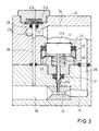
- Fig. 3 shows a functionally largely corresponding to Fig. 2 valve unit with a fixed throttle 16 and influencing its passage cross section Control valve 17.
- the fixed throttle 16 is in turn between one high-pressure side valve inlet channel 18 and a low-pressure side valve outlet channel 19.
- the mechanical control valve 17 is from one to the other of Fig. 2 identical structure with a control piston 17a, a valve needle 17b, a valve spring 17c, ring seals 20, 21 around the control piston 17a or the valve needle 17b around and inserted into a housing bore Valve body for guiding the valve needle 17b and for receiving the valve spring 17c and to define a lower end stop 22 for the control piston 17a, which on the other hand in the shown upper end position against one abutment 23 abuts the housing.
- the control piston 17a is again with a pressure chamber in connection, here a connection channel 24, which is also like all other components of the valve unit in a common valve housing 25 is located.
- valve unit of FIG. 3 stands for the outlet duct 19 leaving the fixed throttle 16 via an internal housing Connection channel 26 with the connection channel 24 in connection, the there prevailing pressure of the medium in it, the control piston 17a acted upon.
- the mechanical control valve 17 directly with the pressure of the relaxed medium coming from the fixed throttle 16 as Manipulated variable is applied. Otherwise the function of the control valve corresponds 17 that of Fig. 2, i.e. depending on that in the connecting channel 24 prevailing pressure, the control valve leaves the fixed throttle passage cross section unchanged or limited to depending on the connection duct pressure a minimum value.
- valve 3 also includes an in the housing 25 integrated pressure relief valve 27 with a valve pin 27a, which in the shuts off a bypass line 28 during normal valve operation in the position shown, which connects the valve inlet channel 18 on the high pressure side with the connecting channel 24 connects directly.
- the valve pin 27a is on one side of a valve membrane 27b attached, which is supported on its other side against a valve spring 27c.
- the valve pin 27a is surrounded by an annular seal 29 and is on it Head end via the bypass line 28 from the pressure of the valve inlet channel 18 medium supplied on the high pressure side.
- the valve unit of FIG. 3 can be used in an analogous manner to that of FIG. 2 for an expansion element, in particular a CO 2 air conditioning system, whereby it is connected on the low pressure side with its connecting channel 24 to the inlet side of the evaporator, ie the mechanical control valve 17 is from Suction pressure of the refrigerant upstream of the evaporator as a manipulated variable.
- an expansion element in particular a CO 2 air conditioning system
- the mechanical control valve 17 is from Suction pressure of the refrigerant upstream of the evaporator as a manipulated variable.
- the tendency of the mechanical control valve 9, 17 to oscillate can be kept sufficiently low both by the damping behavior of the associated ring seals 13, 14 or 20, 21 and by a suitable choice of the spring characteristic of the associated valve spring 9c, 17c.
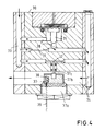
- Fig. 4 shows another usable for an air conditioner expansion device Valve unit.
- This valve unit has in a common housing 30 a first fixed throttle 31 and a second fixed throttle 32, which are parallel between an inlet duct 33 on the high pressure side and an outlet duct 33 on the low pressure side 34 are arranged, a pressure relief valve 35 in one of the two fixed throttles 31 bypass line 36 and a thermal control valve 37, that affects the passage cross section of the second fixed throttle 32.
- the pressure relief valve 35 corresponds completely to that in structure and mode of operation of Fig. 1, which can be referred to.
- the thermal control valve 37 includes a base 37a, the one Expansion tank 37b carries.
- the expansion tank 37b is located on the low pressure side Outlet channel 34 of the valve unit and is with a suitable Fluid, like a waxy substance, fills the temperature of the low pressure side Medium in the outlet channel 34 assumes. This temperature determines as a manipulated variable via the volume expansion coefficient of the fluid in Expansion tank 37b the position of a movable to the expansion tank 37b coupled valve needle 37c, which, depending on the position, the passage cross section leaves the second fixed throttle 32 completely free or variable until completely closed limited and thereby that in the valve inlet channel 32 High pressure affected.
- thermal control valve 37 38 there is an electric heating element for the thermal control valve 37 38, e.g. a PTC element, provided in the expansion tank 37b, which via Heating lines 39 can be energized, which from the expansion tank 37b and through the control valve base 37a to the outside of the housing 30 of the valve unit are guided.
- the thermal control valve 37 controlled externally and thus integrated into an externally specified control concept become.
- the heating current or the physical one determining it Size as manipulated variable for the setting of the thermal control valve 37.
- valve unit of FIG. 4 is in turn also particularly suitable for an expansion element of a CO 2 vehicle air conditioning system.
- the valve unit is coupled with its inlet channel 33 on the high-pressure side to the outlet of the gas cooler or the internal heat exchanger and with its outlet channel 34 to the low-pressure side of the CO 2 refrigerant circuit before or after the evaporator.
- the refrigerant then flows from the gas cooler or the inside Heat exchanger in the inlet channel 33 of the valve unit, is via the two parallel fixed throttles 31, 32 relaxes and flows through the outlet channel 34 to the evaporator.
- the refrigerant flow through the valve unit is indicated by the corresponding one Arrows symbolized.
- the pressure relief valve 35 protects against one high refrigerant pressure on the high pressure side.
- the thermal control valve 37 the high-pressure refrigerant can be operated with a relatively low level of control technology Set the effort in the various plant operating states so that the COP or the refrigeration capacity is as close as possible is at its maximum value.
- the high-pressure refrigerant value from the low-pressure side temperature of the relaxed to the evaporator Refrigerant influenced by the expansion tank 37b in this Refrigerant flow is the high-pressure refrigerant value from the low-pressure side temperature of the relaxed to the evaporator Refrigerant influenced by the expansion tank 37b in this Refrigerant flow.
- the temperature of the fluid in the expansion tank 37b assumes corresponds to the saturation temperature of the refrigerant at the appropriate pressure.
- suction pressure i.e., suction pressure
- the valve needle 37c increases the free throttle cross section of the second Fixed throttle 32 so that the high pressure increases.
- the suction pressure certain upper limit of e.g. Has reached 45bar is the second fixed throttle 32 closed, while the other fixed throttle 31 continues high-pressure refrigerant can flow throttled to the low-pressure side.
- the position of the valve needle 37c then changes as the suction pressure continues to rise no more, and it comes up for an exemplary design case a certain
- the low-temperature side refrigerant temperature thus serves via the expansion tank 37b and thus indirectly the suction pressure associated with it as a manipulated variable for regulating the high-pressure refrigerant.
- the heating current for the heating element 38 via the external heating lines 39 or a physical variable determining it as a further manipulated variable Serve regulation. This is where the vehicle ambient temperature comes in, for example or the speed of the vehicle engine into consideration, in which case one in each case heating current signal dependent on one or both of these quantities is generated.
- a two-stage control depending on the engine speed be provided in which the thermal control valve 37 and thus the expansion organ as a whole for a range of lower engine speeds is set differently than for a range of high engine speeds, whereby is taken into account that the engine speed, among other things, the performance of the Air conditioning compressor determined. Vibration tendencies of the thermal Control valve 37, as in certain conditions when operating the air conditioning can occur by appropriate selection of the properties of the used expansion material can be counteracted in the expansion tank 37b.
- the expansion tank 37b of the thermal control valve 37 in the refrigerant flow section downstream of the evaporator be arranged.
- a valve unit is used, the opposite that of Fig. 4 is modified so that according to the 2 the refrigerant flow channel influencing the control valve 37 of the outlet channel coupled to the fixed throttles 31, 32 is kept separate.
- the outlet channel is then on the evaporator inlet side coupled, during the influencing the thermal control valve 37 Refrigerant flow channel of the valve unit in the refrigerant flow section between the evaporator and the compressor.
- an expansion device can be provided the main throttling element is a pure control valve without fixed throttling properties involves which of the suction pressure or one related to it other physical variable than the manipulated variable for the purpose of controlling the High pressure is applied.
Landscapes
- Engineering & Computer Science (AREA)
- Physics & Mathematics (AREA)
- Mechanical Engineering (AREA)
- Thermal Sciences (AREA)
- General Engineering & Computer Science (AREA)
- Fluid Mechanics (AREA)
- Chemical & Material Sciences (AREA)
- Chemical Kinetics & Catalysis (AREA)
- Air-Conditioning For Vehicles (AREA)
- Temperature-Responsive Valves (AREA)
- Details Of Valves (AREA)
- Compression-Type Refrigeration Machines With Reversible Cycles (AREA)
Applications Claiming Priority (2)
| Application Number | Priority Date | Filing Date | Title |
|---|---|---|---|
| DE19852127 | 1998-11-12 | ||
| DE19852127A DE19852127B4 (de) | 1998-11-12 | 1998-11-12 | Expansionsorgan und hierfür verwendbare Ventileinheit |
Publications (2)
| Publication Number | Publication Date |
|---|---|
| EP1001229A2 true EP1001229A2 (fr) | 2000-05-17 |
| EP1001229A3 EP1001229A3 (fr) | 2001-09-19 |
Family
ID=7887513
Family Applications (1)
| Application Number | Title | Priority Date | Filing Date |
|---|---|---|---|
| EP99122508A Withdrawn EP1001229A3 (fr) | 1998-11-12 | 1999-11-11 | Elément d'expansion et unité de soupape à utiliser avec cet élément |
Country Status (5)
| Country | Link |
|---|---|
| US (1) | US6430950B1 (fr) |
| EP (1) | EP1001229A3 (fr) |
| JP (1) | JP4279957B2 (fr) |
| DE (1) | DE19852127B4 (fr) |
| FR (1) | FR2785964B1 (fr) |
Cited By (6)
| Publication number | Priority date | Publication date | Assignee | Title |
|---|---|---|---|---|
| WO2001006183A1 (fr) * | 1999-07-16 | 2001-01-25 | Zexel Valeo Climate Control Corporation | Cycle frigorifique |
| WO2001027543A1 (fr) * | 1999-10-08 | 2001-04-19 | Zexel Valeo Climate Control Corporation | Cycle frigorifique |
| WO2006079408A1 (fr) * | 2005-01-27 | 2006-08-03 | Otto Egelhof Gmbh & Co. Kg | Soupape de detente |
| FR2900222A1 (fr) * | 2006-04-25 | 2007-10-26 | Valeo Systemes Thermiques | Circuit de climatisation a cycle supercritique. |
| EP1875142A4 (fr) * | 2005-03-18 | 2008-05-14 | Carrier Comm Refrigeration Inc | Refrigeration transcritique avec vanne de decharge d'addition de pression |
| EP3139114A1 (fr) * | 2015-08-28 | 2017-03-08 | Hyundai Motor Company | Soupape de détente d'un système de climatisation de véhicule et système de climatisation de véhicule comprenant celui-ci |
Families Citing this family (28)
| Publication number | Priority date | Publication date | Assignee | Title |
|---|---|---|---|---|
| US6857281B2 (en) * | 2000-09-14 | 2005-02-22 | Xdx, Llc | Expansion device for vapor compression system |
| US6915648B2 (en) * | 2000-09-14 | 2005-07-12 | Xdx Inc. | Vapor compression systems, expansion devices, flow-regulating members, and vehicles, and methods for using vapor compression systems |
| DE10063273A1 (de) * | 2000-12-19 | 2002-07-04 | Bosch Gmbh Robert | Überdruckerzeugungsvorrichtung und Ventil |
| JP2002274147A (ja) * | 2001-01-12 | 2002-09-25 | Japan Climate Systems Corp | 車両用空調装置 |
| EP1369648A3 (fr) * | 2002-06-04 | 2004-02-04 | Sanyo Electric Co., Ltd. | Système de cycle à frigorigène supercritique |
| DE10303530B4 (de) * | 2003-01-29 | 2004-11-11 | Danfoss A/S | Abtauventil für eine Kälteanlage |
| DE10324955B4 (de) * | 2003-06-03 | 2010-04-29 | Audi Ag | Klimaanlage zum Beheizen und Kühlen eines Raumes |
| JP4255807B2 (ja) * | 2003-11-06 | 2009-04-15 | 株式会社不二工機 | 電磁リリーフ弁付膨張弁 |
| DE102004010997B3 (de) * | 2004-03-03 | 2005-06-23 | Otto Egelhof Gmbh & Co. Kg | Expansionsventil und Verfahren zu dessen Steuerung |
| JP4351561B2 (ja) * | 2004-03-09 | 2009-10-28 | 株式会社鷺宮製作所 | 冷凍サイクル装置および電動コントロール弁 |
| FR2868830B1 (fr) * | 2004-04-09 | 2012-11-30 | Valeo Climatisation | Dispositif de detente ameliore pour circuit de climatisation |
| EP1666817A3 (fr) * | 2004-12-01 | 2007-01-17 | Fujikoki Corporation | Vanne de régulation de pression |
| US7178362B2 (en) * | 2005-01-24 | 2007-02-20 | Tecumseh Products Cormpany | Expansion device arrangement for vapor compression system |
| US20080202140A1 (en) * | 2005-03-18 | 2008-08-28 | Carrier Commercial Refrigeration, Inc. | High Side Pressure Regulation For Transcritical Vapor Compression System |
| DE102005017918A1 (de) * | 2005-04-18 | 2006-10-19 | Behr Gmbh & Co. Kg | Überdrucksicherheitseinrichtung für einen Kältemittelkreislauf |
| DE102005018673A1 (de) * | 2005-04-21 | 2006-10-26 | Behr Gmbh & Co. Kg | Klimaanlage, insbesondere für ein Kraftfahrzeug |
| DE102005032458A1 (de) * | 2005-07-12 | 2007-01-25 | Robert Bosch Gmbh | Kälteanlage, insbesondere Kraftfahrzeug-Klimaanlage |
| JP2007085489A (ja) * | 2005-09-22 | 2007-04-05 | Fuji Koki Corp | 圧力制御弁 |
| JP4509000B2 (ja) * | 2005-10-04 | 2010-07-21 | 株式会社不二工機 | 圧力制御弁 |
| DE102006021327A1 (de) * | 2006-05-05 | 2007-11-08 | Otto Egelhof Gmbh & Co. Kg | Verfahren zur Steuerung eines Expansionsventils sowie Expansionsventil, insbesondere für mit CO2Kältemittel betriebene Fahrzeugklimaanlagen |
| DE102006061091A1 (de) * | 2006-12-22 | 2008-06-26 | BSH Bosch und Siemens Hausgeräte GmbH | Kühlmöbel mit wenigstens zwei thermisch voneinander getrennten Fächern |
| US8047449B2 (en) * | 2009-01-28 | 2011-11-01 | Automotive Components Holdings Llc | Automotive thermostatic expansion valve with reduced hiss |
| CN101900463B (zh) * | 2010-06-30 | 2012-05-02 | 广东美的电器股份有限公司 | 一种空调器及空调器控制方法 |
| DE102012224121A1 (de) * | 2012-12-21 | 2014-06-26 | Bayerische Motoren Werke Aktiengesellschaft | Expansionsventil für einen Kühlkreislauf |
| DE102016200576A1 (de) * | 2016-01-18 | 2017-08-10 | Bayerische Motoren Werke Aktiengesellschaft | Expansionsorgan und Verfahren zur Regelung bzw. Steuerung eines Kältemittelmassenstroms, Verwendung für einen Kältekreis eines Kraftfahrzeugs, sowie Kraftfahrzeug |
| JP6890021B2 (ja) * | 2017-02-28 | 2021-06-18 | 三菱重工サーマルシステムズ株式会社 | ターボ冷凍機、及びターボ冷凍機の運転方法 |
| TWI667442B (zh) * | 2018-08-01 | 2019-08-01 | 群光電能科技股份有限公司 | 閥、膨脹閥及其步進控制方法 |
| CN115751782B (zh) * | 2022-12-15 | 2023-09-12 | 徐州市三禾自动控制设备有限公司 | 一种菌类冷库用制冷装置 |
Citations (3)
| Publication number | Priority date | Publication date | Assignee | Title |
|---|---|---|---|---|
| EP0438625A2 (fr) | 1990-01-26 | 1991-07-31 | TGK CO., Ltd. | Soupape de détente |
| EP0701096A2 (fr) | 1994-09-09 | 1996-03-13 | Mercedes-Benz Ag | Procédé de fonctionnement d'une installation productrice de froid pour la climatisation de véhicules et installation productrice de froid pour sa mise en oeuvre |
| EP0786632A2 (fr) | 1996-01-25 | 1997-07-30 | Denso Corporation | Système de réfrigération avec soupape de commande de pression |
Family Cites Families (21)
| Publication number | Priority date | Publication date | Assignee | Title |
|---|---|---|---|---|
| DE1075646B (de) * | 1960-02-18 | Klemenz Stutt gart Mohrmgcn Rudolf | Thermostatisches Em spritzventil fur Kälteanlagen | |
| US2654976A (en) * | 1949-02-02 | 1953-10-13 | Jorgensen Hans Jorgen | Regulating valve for refrigerating installations |
| US3150502A (en) * | 1962-07-25 | 1964-09-29 | Singer Co | No-freeze refrigerant control |
| US3252294A (en) * | 1963-12-12 | 1966-05-24 | Gen Motors Corp | Refrigerating flow control means |
| US3285030A (en) * | 1964-11-02 | 1966-11-15 | Gen Electric | Refrigeration system including high pressure limit control means |
| US4032070A (en) * | 1974-08-07 | 1977-06-28 | Danfoss A/S | Thermostatic expansion valve for refrigeration installations |
| US4236669A (en) * | 1978-12-18 | 1980-12-02 | Borg-Warner Corporation | Thermostatic expansion valve with lead-lag compensation |
| DE3151016A1 (de) * | 1981-12-23 | 1983-07-28 | Loewe Pumpenfabrik GmbH, 2120 Lüneburg | Entspannungseinrichtung fuer kaeltemittelkreislaeufe |
| JPS58146778A (ja) * | 1982-02-23 | 1983-09-01 | Matsushita Refrig Co | 熱応動弁 |
| DE3510776A1 (de) * | 1985-03-25 | 1986-10-02 | Audi AG, 8070 Ingolstadt | Verfahren zum betreiben einer klimaanlage, insbesondere fuer fahrzeuge, sowie klimaanlage zur durchfuehrung des verfahrens |
| JPS63129169U (fr) * | 1987-02-16 | 1988-08-24 | ||
| JPS63150257U (fr) * | 1987-03-20 | 1988-10-03 | ||
| US5195331A (en) * | 1988-12-09 | 1993-03-23 | Bernard Zimmern | Method of using a thermal expansion valve device, evaporator and flow control means assembly and refrigerating machine |
| DE3922591A1 (de) * | 1989-07-10 | 1991-01-24 | Danfoss As | Servogesteuertes expansionsventil fuer ein leicht verdampfbares fluid |
| US4951478A (en) * | 1989-10-24 | 1990-08-28 | Chrysler Corporation | Variable capacity control valve |
| DE4036059A1 (de) * | 1990-11-13 | 1992-05-14 | Weiss Umwelttechnik Gmbh | Kaelteanlage sowie expansionsventil fuer insbesondere eine solche |
| DE4341579A1 (de) * | 1993-01-21 | 1994-08-04 | Flitsch E Gmbh & Co | Ventilanordnung insbesondere für Kälteanlagen |
| JP3637651B2 (ja) * | 1995-03-22 | 2005-04-13 | 株式会社デンソー | 温度式膨張弁 |
| EP0837291B1 (fr) * | 1996-08-22 | 2005-01-12 | Denso Corporation | Système frigorifique du type à compression de vapeur |
| IT1296367B1 (it) * | 1997-11-10 | 1999-06-25 | Pegoraro Sas Di Pegoraro Giorg | Gruppo valvola per la regolazione del flusso di fluidi in pressione. |
| JPH11248272A (ja) * | 1998-01-05 | 1999-09-14 | Denso Corp | 超臨界冷凍サイクル |
-
1998
- 1998-11-12 DE DE19852127A patent/DE19852127B4/de not_active Expired - Fee Related
-
1999
- 1999-11-02 JP JP31265699A patent/JP4279957B2/ja not_active Expired - Fee Related
- 1999-11-10 FR FR9914123A patent/FR2785964B1/fr not_active Expired - Fee Related
- 1999-11-11 EP EP99122508A patent/EP1001229A3/fr not_active Withdrawn
- 1999-11-12 US US09/438,390 patent/US6430950B1/en not_active Expired - Fee Related
Patent Citations (3)
| Publication number | Priority date | Publication date | Assignee | Title |
|---|---|---|---|---|
| EP0438625A2 (fr) | 1990-01-26 | 1991-07-31 | TGK CO., Ltd. | Soupape de détente |
| EP0701096A2 (fr) | 1994-09-09 | 1996-03-13 | Mercedes-Benz Ag | Procédé de fonctionnement d'une installation productrice de froid pour la climatisation de véhicules et installation productrice de froid pour sa mise en oeuvre |
| EP0786632A2 (fr) | 1996-01-25 | 1997-07-30 | Denso Corporation | Système de réfrigération avec soupape de commande de pression |
Cited By (7)
| Publication number | Priority date | Publication date | Assignee | Title |
|---|---|---|---|---|
| WO2001006183A1 (fr) * | 1999-07-16 | 2001-01-25 | Zexel Valeo Climate Control Corporation | Cycle frigorifique |
| WO2001027543A1 (fr) * | 1999-10-08 | 2001-04-19 | Zexel Valeo Climate Control Corporation | Cycle frigorifique |
| WO2006079408A1 (fr) * | 2005-01-27 | 2006-08-03 | Otto Egelhof Gmbh & Co. Kg | Soupape de detente |
| EP1875142A4 (fr) * | 2005-03-18 | 2008-05-14 | Carrier Comm Refrigeration Inc | Refrigeration transcritique avec vanne de decharge d'addition de pression |
| FR2900222A1 (fr) * | 2006-04-25 | 2007-10-26 | Valeo Systemes Thermiques | Circuit de climatisation a cycle supercritique. |
| EP1850075A1 (fr) * | 2006-04-25 | 2007-10-31 | Valeo Systèmes Thermiques | Circuit de climatisation à cycle supercritique |
| EP3139114A1 (fr) * | 2015-08-28 | 2017-03-08 | Hyundai Motor Company | Soupape de détente d'un système de climatisation de véhicule et système de climatisation de véhicule comprenant celui-ci |
Also Published As
| Publication number | Publication date |
|---|---|
| US6430950B1 (en) | 2002-08-13 |
| EP1001229A3 (fr) | 2001-09-19 |
| JP4279957B2 (ja) | 2009-06-17 |
| JP2000146365A (ja) | 2000-05-26 |
| DE19852127B4 (de) | 2008-09-11 |
| FR2785964A1 (fr) | 2000-05-19 |
| DE19852127A1 (de) | 2000-05-18 |
| FR2785964B1 (fr) | 2002-09-13 |
Similar Documents
| Publication | Publication Date | Title |
|---|---|---|
| EP1001229A2 (fr) | Elément d'expansion et unité de soupape à utiliser avec cet élément | |
| DE10339001B4 (de) | Kältemittelkreislauf mit einem Ejektor mit bezüglich ihres Drosselgrads änderbarer Düse | |
| DE2512569A1 (de) | Klimaanlage, insbesondere fuer kraftfahrzeuge | |
| DE10355315A1 (de) | Ejektorpumpen-Kreislaufsystem | |
| DE2603682C3 (de) | Ventilanordnung für Kälteanlagen | |
| DE102004010997B3 (de) | Expansionsventil und Verfahren zu dessen Steuerung | |
| DE10028416A1 (de) | Steuerung für eine variable Pumpe für einen Hydraulikventilatorantrieb | |
| EP1599696B1 (fr) | Organe d'expansion pour systeme de climatisation | |
| DE2029289B2 (de) | Thermostatisch gesteuertes Ventil für eine Klimaanlage in einem Kraftfahrzeug | |
| DE69915001T2 (de) | Vorgesteuertes Durchflussregelungsventil | |
| EP0356642A1 (fr) | Soupape thermostatique de détente | |
| WO2001007825A2 (fr) | Procede de regulation de la pression dans un reservoir cryogenique et dispositif correspondant | |
| DE69926287T2 (de) | Entspannungsventil | |
| DE60212502T2 (de) | Kältekreislauf | |
| DE102005003968A1 (de) | Expansionsventil und Verfahren zu dessen Steuerung | |
| DE3822781A1 (de) | Geschlossener kuehlmittelkreislauf einer kraftfahrzeug-klimaanlage | |
| WO2008064816A1 (fr) | Soupape d'expansion thermostatique pour circuits de réfrigération ou à pompes à chaleur présentant une fonction de sécurité commandée mécaniquement | |
| DE69316386T2 (de) | Expansionsventil für eine klimaanlage mit einem proportionalmagnet | |
| DE3047368A1 (de) | Temperatursensitives steuersystem | |
| DE10258524A1 (de) | Kältemittelkreislauf für eine Kfz-Klimaanlage | |
| DE10324955B4 (de) | Klimaanlage zum Beheizen und Kühlen eines Raumes | |
| DE102009030041A1 (de) | Fahrzeug-Klimasystem | |
| DE69310756T2 (de) | Expansionsventil für klimaanlage | |
| DE2709534A1 (de) | Thermostatisches expansionsventil | |
| DE102006007756A1 (de) | Dekompressionsvorrichtung für einen Kühlkreis |
Legal Events
| Date | Code | Title | Description |
|---|---|---|---|
| PUAI | Public reference made under article 153(3) epc to a published international application that has entered the european phase |
Free format text: ORIGINAL CODE: 0009012 |
|
| AK | Designated contracting states |
Kind code of ref document: A2 Designated state(s): AT BE CH CY DE DK ES FI FR GB GR IE IT LI LU MC NL PT SE Kind code of ref document: A2 Designated state(s): ES GB IT SE |
|
| AX | Request for extension of the european patent |
Free format text: AL;LT;LV;MK;RO;SI |
|
| RIN1 | Information on inventor provided before grant (corrected) |
Inventor name: KRAUSS, HANS-JOACHIM Inventor name: MITTELSTRASS, HAGEN Inventor name: STAFFA, KARL-HEINZ Inventor name: WALTER, CHRISTOPH Inventor name: DIENHART, BERND, DR. Inventor name: VAN DOAN, NGUYEN Inventor name: SEIPEL, VOLKER Inventor name: HINRICHS, JAN, DR. |
|
| PUAL | Search report despatched |
Free format text: ORIGINAL CODE: 0009013 |
|
| AK | Designated contracting states |
Kind code of ref document: A3 Designated state(s): AT BE CH CY DE DK ES FI FR GB GR IE IT LI LU MC NL PT SE |
|
| AX | Request for extension of the european patent |
Free format text: AL;LT;LV;MK;RO;SI |
|
| RIC1 | Information provided on ipc code assigned before grant |
Free format text: 7F 25B 41/06 A, 7B 60H 1/00 B, 7B 60H 1/32 B, 7G 05D 23/02 B |
|
| 17P | Request for examination filed |
Effective date: 20020319 |
|
| AKX | Designation fees paid |
Free format text: ES GB IT SE |
|
| REG | Reference to a national code |
Ref country code: DE Ref legal event code: 8566 |
|
| 17Q | First examination report despatched |
Effective date: 20031110 |
|
| GRAP | Despatch of communication of intention to grant a patent |
Free format text: ORIGINAL CODE: EPIDOSNIGR1 |
|
| GRAS | Grant fee paid |
Free format text: ORIGINAL CODE: EPIDOSNIGR3 |
|
| STAA | Information on the status of an ep patent application or granted ep patent |
Free format text: STATUS: THE APPLICATION IS DEEMED TO BE WITHDRAWN |
|
| 18D | Application deemed to be withdrawn |
Effective date: 20050426 |